2005 MITSUBISHI 380 coolant level
[x] Cancel search: coolant levelPage 918 of 1500
ENGINE COOLING DIAGNOSIS
ENGINE COOLING14-3
SYMPTOM CHARTM1141005600393
SYMPTOM PROCEDURES
INSPECTION PROCEDURE 1: Coolant Leak
DIAGNOSIS
STEP 1. Check for coolant leaks.
When pressure testing the cooling system, slowly
release cooling system pressure to avoid being
burned by hot coolant.
Be sure to completely clean away any moisture from
the places checked.
When the tester is removed, be careful not to spill any
coolant.
When installing and removing the tester and when test-
ing, be careful not to deform the filler neck of the radia-
tor.
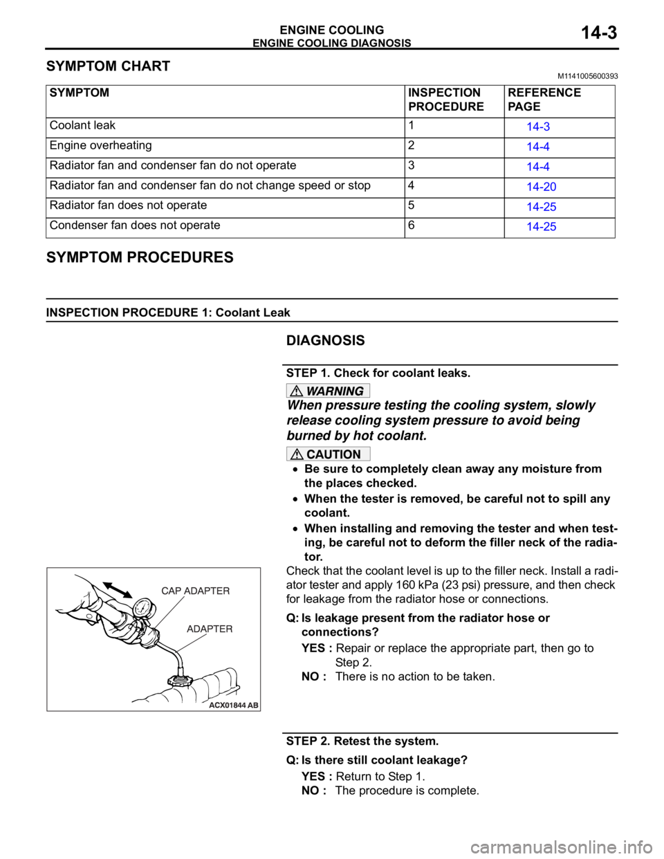
Check that the coolant level is up to the filler neck. Install a radi-
ator tester and apply 160 kPa (23 psi) pressure, and then check
for leakage from the radiator hose or connections.
Q: Is leakage present from the radiator hose or
connections?
YES : Repair or replace the appropriate part, then go to
St e p 2 .
NO : There is no action to be taken.
STEP 2. Retest the system.
Q: Is there still coolant leakage?
YES : Return to Step 1.
NO : The procedure is complete. SYMPTOM INSPECTION
PROCEDUREREFERENCE
PA G E
Coolant leak 1
14-3
Engine overheating 2
14-4
Radiator fan and condenser fan do not operate 3
14-4
Radiator fan and condenser fan do not change speed or stop 4
14-20
Radiator fan does not operate 5
14-25
Condenser fan does not operate 6
14-25
Page 941 of 1500
ON-VEHICLE SERVICE
ENGINE COOLING14-26
DIAGNOSIS
STEP 1. Check the condenser fan motor.
Condenser fan motor check. (Refer to GROUP 55, Condenser
and Condenser Fan Motor.
Q: Is the condenser fan motor in good condition?
YES : Go to Step 2.
NO : Replace the condenser fan motor, then go to Step 3.
STEP 2. Check the fan controller.
Refer to 29.
Q: Is the fan controller in good condition?
YES : Go to Step 3.
NO : Replace the fan motor and fan controller (Refer to
14-25). Then go to Step 3.
STEP 3. Check the symptoms.
Q: Do the condenser fan operate?
YES : This symptom is complete.
NO : Return to Step 1.
ON-VEHICLE SERVICE
ENGINE COOLANT LEAK CHECKM1141001000333
When pressure testing the cooling system, slowly
release cooling system pressure to avoid getting
burned by hot coolant.
Be sure to completely clean away any moisture from
the places checked.
When the tester is taken out, be careful not to spill any
coolant.
Be careful when installing and removing the tester and
when testing not to deform the filler neck of the radia-
tor.
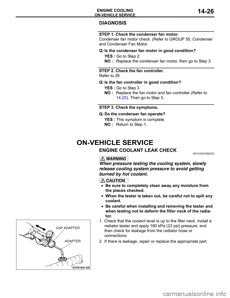
1. Check that the coolant level is up to the filler neck. Install a
radiator tester and apply 160 kPa (23 psi) pressure, and
then check for leakage from the radiator hose or
connections.
2. If there is leakage, repair or replace the appropriate part.
Page 947 of 1500
RADIATOR
ENGINE COOLING14-32
RADIATOR
REMOVAL AND INSTALLATIONM1141001500521
Pre-removal Operation
Engine Coolant Draining (Refer to 27).
Air Cleaner Removal (Refer to GROUP 15, Air Cleaner 4).Post-installation Operation
Air Cleaner Installation (Refer to GROUP 15 4).
Engine Coolant Refilling and Level Check (Refer to 27).
A/T Fluid Refilling and Level Check (Refer to GROUP 00,
Maintenance Service 45).
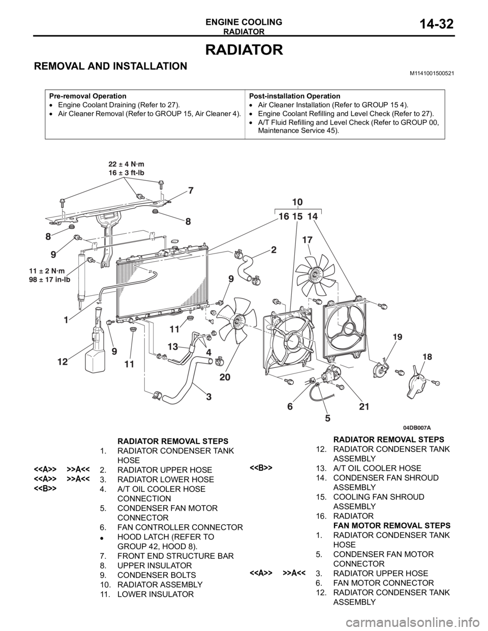
RADIATOR REMOVAL STEPS
1. RADIATOR CONDENSER TANK
HOSE
<> >>A<<2. RADIATOR UPPER HOSE
<> >>A<<3. RADIATOR LOWER HOSE
<>4. A/T OIL COOLER HOSE
CONNECTION
5. CONDENSER FAN MOTOR
CONNECTOR
6. FAN CONTROLLER CONNECTOR
HOOD LATCH (REFER TO
GROUP 42, HOOD 8).
7. FRONT END STRUCTURE BAR
8. UPPER INSULATOR
9. CONDENSER BOLTS
10. RADIATOR ASSEMBLY
11. LOWER INSULATOR12. RADIATOR CONDENSER TANK
ASSEMBLY
<>13. A/T OIL COOLER HOSE
14. CONDENSER FAN SHROUD
ASSEMBLY
15. COOLING FAN SHROUD
ASSEMBLY
16. RADIATOR
FAN MOTOR REMOVAL STEPS
1. RADIATOR CONDENSER TANK
HOSE
5. CONDENSER FAN MOTOR
CONNECTOR
<> >>A<<3. RADIATOR UPPER HOSE
6. FAN MOTOR CONNECTOR
12. RADIATOR CONDENSER TANK
ASSEMBLY RADIATOR REMOVAL STEPS
Page 1257 of 1500

RECOMMENDED LUBRICANTS AND LUBRICANT CAPACITIES TABLE
GENERAL00-36
SELECTION OF COOLANT
.
COOLANT
Relationship between Coolant Concentration and Specific Gravity
If the concentration of the coolant is below 30%, the anti-corrosion property will be adversely
affected. In addition, if the concentration is above 50%, both the anti-freeze and engine cooling
properties will decrease, affecting the engine adversely. For these reasons, be sure to maintain
the concentration level within the specified range.
Do not use a mixture of different brands of anti-freeze.
Example
The safe operating temperature is
15C (5 F) when the specific gravity is 1.058 at the coolant temperature
of 20
C (68F) ENGINE COOLANT TEMPERATURE
C (F) AND SPECIFIC GRAVITYFREEZING
TEMPERATURESAFE OPERATING
TEMPERATURECOOLANT
CONCENTRATION
(SPECIFIC
VOLUME)
10 20 30 40 50
C (F)C (F)%
1.054 1.050 1.046 1.042 1.036
16 (3.2)11 ( 1 2 . 2 )30
1.063 1.058 1.054 1.049 1.044
20 (4)15 (5)35
1.071 1.067 1.062 1.057 1.052
25 (13)20 (4)40
1.079 1.074 1.069 1.064 1.058
30 (22)25 (13)45
1.087 1.082 1.076 1.070 1.064
36 (32.8)31 (23.8)50
1.095 1.090 1.084 1.077 1.070
42 (44)37 (35)55
1.103 1.098 1.092 1.084 1.076
50 (58)45 (49)60
Page 1265 of 1500
MAINTENANCE SERVICE
GENERAL00-44
8. EXHAUST SYSTEM (CONNECTIONS PORTION
OF MUFFLER, MUFFLER PIPES AND
CONVERTER HEAT SHIELDS) (CHECK AND
SERVICE AS REQUIRED)
M1001005800299
1. Check for holes and exhaust gas leaks due to damage,
corrosion, etc.
2. Check the joints and connections for looseness and exhaust
gas leaks.
3. Check the rubber hangers and brackets for damage.
9. ENGINE OIL (CHANGE)M1001002600360
Use the specified oil. (Refer to P.00-35.)
Use care as oil could be hot.
1. After warming up the engine, remove the oil filler cap.
2. Remove the drain plug to allow the engine oil to drain.
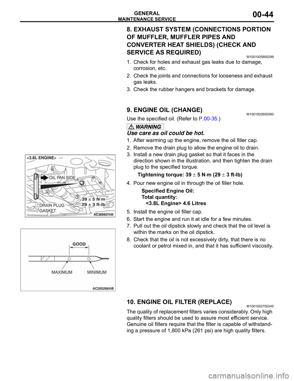
3. Install a new drain plug gasket so that it faces in the
direction shown in the illustration, and then tighten the drain
plug to the specified torque.
Tightening torque: 39
5 Nm (29 3 ft-lb)
4. Pour new engine oil in through the oil filler hole.
Specified Engine Oil:
To ta l q u a n t i t y :
<3.8L Engine> 4.6 Litres
5. Install the engine oil filler cap.
6. Start the engine and run it at idle for a few minutes.
7. Pull out the oil dipstick slowly and check that the oil level is
within the marks on the oil dipstick.
8. Check that the oil is not excessively dirty, that there is no
coolant or petrol mixed in, and that it has sufficient viscosity.
10. ENGINE OIL FILTER (REPLACE)M1001002700345
The quality of replacement filters varies considerably. Only high
quality filters should be used to assure most efficient service.
Genuine oil filters require that the filter is capable of withstand-
ing a pressure of 1,800 kPa (261 psi) are high quality filters.
.
Page 1412 of 1500
EMISSION CONTROL
ENGINE AND EMISSION CONTROL17-81
EVAPORATIVE EMISSION CONTROL SYSTEM
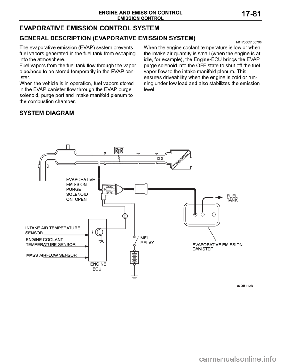
GENERAL DESCRIPTION (EVAPORATIVE EMISSION SYSTEM)M1173005100706
The evaporative emission (EVAP) system prevents
fuel vapors generated in the fuel tank from escaping
into the atmosphere.
Fuel vapors from the fuel tank flow through the vapor
pipe/hose to be stored temporarily in the EVAP can-
ister.
When the vehicle is in operation, fuel vapors stored
in the EVAP canister flow through the EVAP purge
solenoid, purge port and intake manifold plenum to
the combustion chamber.When the engine coolant temperature is low or when
the intake air quantity is small (when the engine is at
idle, for example), the Engine-ECU brings the EVAP
purge solenoid into the OFF state to shut off the fuel
vapor flow to the intake manifold plenum. This
ensures driveability when the engine is cold or run-
ning under low load and also stabilizes the emission
level.
SYSTEM DIAGRAM
Page 1484 of 1500
AUTOMATIC TRANSMISSION DIAGNOSIS
AUTOMATIC TRANSMISSION23A-25
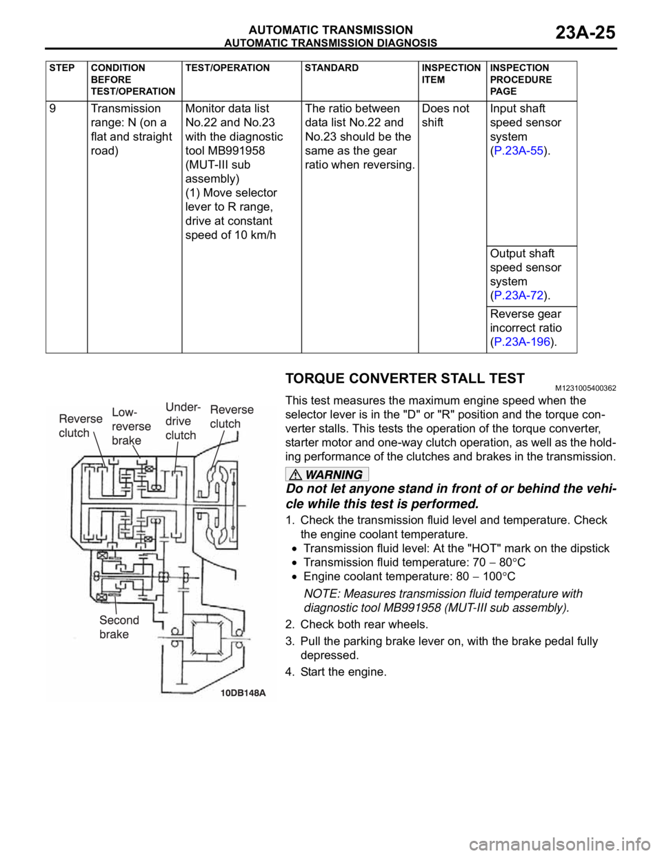
TORQUE CONVERTER STALL TESTM1231005400362
This test measures the maximum engine speed when the
selector lever is in the "D" or "R" position and the torque con-
verter stalls. This tests the operation of the torque converter,
starter motor and one-way clutch operation, as well as the hold-
ing performance of the clutches and brakes in the transmission.
Do not let anyone stand in front of or behind the vehi-
cle while this test is performed.
1. Check the transmission fluid level and temperature. Check
the engine coolant temperature.
Transmission fluid level: At the "HOT" mark on the dipstick
Transmission fluid temperature: 70 80C
Engine coolant temperature: 80 100C
NOTE: Measures transmission fluid temperature with
diagnostic tool MB991958 (MUT-III sub assembly).
2. Check both rear wheels.
3. Pull the parking brake lever on, with the brake pedal fully
depressed.
4. Start the engine. 9 Transmission
range: N (on a
flat and straight
road)Monitor data list
No.22 and No.23
with the diagnostic
tool MB991958
(MUT-III sub
assembly)
(1) Move selector
lever to R range,
drive at constant
speed of 10 km/hThe ratio between
data list No.22 and
No.23 should be the
same as the gear
ratio when reversing.Does not
shiftInput shaft
speed sensor
system
(P.23A-55).
Output shaft
speed sensor
system
(P.23A-72).
Reverse gear
incorrect ratio
(P.23A-196).
STEP CONDITION
BEFORE
TEST/OPERATIONTEST/OPERATION STANDARD INSPECTION
ITEMINSPECTION
PROCEDURE
PA G E
Page 1485 of 1500
AUTOMATIC TRANSMISSION DIAGNOSIS
AUTOMATIC TRANSMISSION23A-26
The throttle should not be fully open for any more than
five seconds.
If you repeat the stall test when the transmission fluid
temperature is greater than 80
C, move the selector
lever to the "N" position and let the engine run at
approximately 1,000 r/min for at least one minute. Wait
until the transmission fluid temperature returns to 80
C
or less.
5. Move the selector lever to the "D" position. Fully depress the
accelerator pedal and read the maximum engine speed at
this time.
Standard value: Stall speed: 2,100
2,600 r/min
6. Move the selector lever to the "R" position. Fully depress the
accelerator pedal and read the maximum engine speed.
Standard value: Stall speed: 2,100
2,600 r/min
TORQUE CONVERTER STALL TEST JUDGMENT
RESULTS
1. Stall speed is too high in both "D" and "R" range
Malfunction of the torque converter (Slippage on the splines
of the torque converter and the input shaft)
Low line pressure
Low-reverse brake slippage and malfunction of the one-way
clutch
2. Stall speed is too high in "D" range only
Underdrive clutch slippage
3. Stall speed is too high in "R" range only
Reverse clutch slippage
4. Stall speed is too low in both "D" and "R" ranges
Malfunction of the torque converter (Slippage of the
one-way clutch)
Insufficient engine output
HYDRAULIC PRESSURE TESTSM1231005500392
The transmission fluid temperature should be between 70
80C during the test.
1. Check the transmission fluid level and temperature. Check
engine coolant temperature.
Transmission fluid level: "HOT" mark on the dipstick
Transmission fluid temperature: 70 80C
Engine coolant temperature: 80 100C
2. Raise the vehicle so that the wheels are free to turn.