Page 578 of 1500

90-1
GROUP 90
CIRCUIT DIAGRAMS
CONTENTS
HOW TO READ CIRCUIT DIAGRAMS90-3
JUNCTION BLOCK . . . . . . . . . . . . . .90-9
JOINT CONNECTOR . . . . . . . . . . . . .90-11
CENTRALISED JUNCTION . . . . . . . .90-12
POWER DISTRIBUTION SYSTEM . .90-18
STARTING SYSTEM . . . . . . . . . . . . .90-21
IGNITION SYSTEM . . . . . . . . . . . . . .90-22
CHARGING SYSTEM . . . . . . . . . . . .90-23
MULTIPOINT FUEL INJECTION (MPI)
SYSTEM . . . . . . . . . . . . . . . . . . . . . . .90-24
COOLING SYSTEM . . . . . . . . . . . . . .90-29
INVECS-II 5A/T . . . . . . . . . . . . . . . . .90-30
HEADLAMPS . . . . . . . . . . . . . . . . . . .90-35
TAIL LAMP, POSITION LAMP, AND
LICENCE PLATE LAMP . . . . . . . . . .90-38
FOG LAMPS . . . . . . . . . . . . . . . . . . .90-41FRONT DOME LAMP, REAR DOME LAMP,
TRUNK LAMP AND IGNITION KEY HOLE
ILLUMINATION LAMP . . . . . . . . . . . .90-44
GLOVE BOX LAMP . . . . . . . . . . . . . .90-48
VANITY MIRROR LAMP. . . . . . . . . . .90-49
TURN-SIGNAL LAMP AND HAZARD
WARNING LAMP . . . . . . . . . . . . . . . .90-50
BACKUP LAMP . . . . . . . . . . . . . . . . .90-54
STOPLAMP. . . . . . . . . . . . . . . . . . . . .90-55
HORN . . . . . . . . . . . . . . . . . . . . . . . . .90-56
METER AND GAUGE . . . . . . . . . . . . .90-57
BRAKE WARNING LAMP, OIL
PRESSURE WARNING LAMP, FUEL
WARNING LAMP . . . . . . . . . . . . . . . .90-60
POWER WINDOWS . . . . . . . . . . . . . .90-62
CENTRAL DOOR LOCKING
SYSTEM . . . . . . . . . . . . . . . . . . . . . . .90-64
Continued on next page
Page 944 of 1500

ON-VEHICLE SERVICE
ENGINE COOLING14-29
Do not use alcohol or methanol anti-freeze or any
engine coolants mixed with alcohol or methanol
anti-freeze. The use of an improper anti-freeze can
cause corrosion of the aluminum components.
8. By referring to the section on coolant, select an appropriate
concentration for safe operating temperature within the
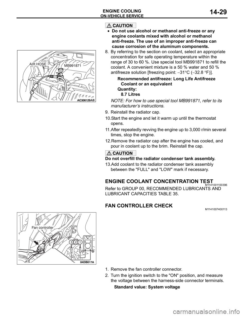
range of 30 to 60 %. Use special tool MB991871 to refill the
coolant. A convenient mixture is a 50 % water and 50 %
antifreeze solution [freezing point:
31C (32.8 F)].
Recommended antifreeze: Long Life Antifreeze
Coolant or an equivalent
Quantity:
8.7 Litres
NOTE: For how to use special tool MB991871, refer to its
manufacturer’s instructions.
9. Reinstall the radiator cap.
10.Start the engine and let it warm up until the thermostat
opens.
11.After repeatedly revving the engine up to 3,000 r/min several
times, stop the engine.
12.Remove the radiator cap after the engine has cooled, and
pour in coolant up to the brim. Reinstall the cap.
Do not overfill the radiator condenser tank assembly.
13.Add coolant to the radiator condenser tank assembly
between the "FULL" and "LOW" mark if necessary.
ENGINE COOLANT CONCENTRATION TESTM1141001100396
Refer to GROUP 00, RECOMMENDED LUBRICANTS AND
LUBRICANT CAPACITIES TABLE 35.
FAN CONTROLLER CHECKM1141007400113
1. Remove the fan controller connector.
2. Turn the ignition switch to the "ON" position, and measure
the voltage between the harness-side connector terminals.
Standard value: System voltage
Page 998 of 1500

STARTING SYSTEM
ENGINE ELECTRICAL16-21
STARTING SYSTEM DIAGNOSISM1162000700293
TROUBLESHOOTING HINTS
The starter motor does not operate at all.
Battery posts, terminals and related accessories con-
tain lead and lead compounds. WASH HANDS AFTER
HANDLING.
Check the starter (coil).
Check for poor contact at the battery terminals and
starter.
Check the transmission range switch.
The starter motor doesn't stop
Check the starter (magnetic switch).
TROUBLESHOOTING GUIDE
The starting system troubleshooting guide is shown in the fol-
lowing steps.
Battery posts, terminals and related accessories con-
tain lead and lead compounds. WASH HANDS AFTER
HANDLING.
STEP 1.
Q: Is the battery in good condition? (Refer to GROUP 54A,
Chassis Electrical
Battery On-vehicle Service
Battery Check P.54A-5.)
YES : Go to Step 2.
NO : Charge or replace the battery.
STEP 2.
Disconnect the starter motor S (solenoid) terminal connec-
tor.
Using a jumper wire, apply battery positive voltage to the
starter motor S (solenoid) terminal.
Check the engine condition.
OK: Turns normally
Q: Dose the starter motor operate normally?
YES :
Check the ignition switch (Refer to GROUP 54A,
Chassis Electrical
Ignition Switch Ignition
Switch
Inspection P.54A-44.)
Check the transmission range switch. (Refer to
GROUP 23A, Automatic Transaxle
On-vehicle
Service
Essential Service Transmission Range
Switch Check P.23A-294.)
Check the wire between the battery and starter
motor S (solenoid) terminal.
NO : Go to Step 3.
Page 1001 of 1500
Page 1002 of 1500

STARTING SYSTEM
ENGINE ELECTRICAL16-25
.
MAGNETIC SWITCH HOLD-IN TEST
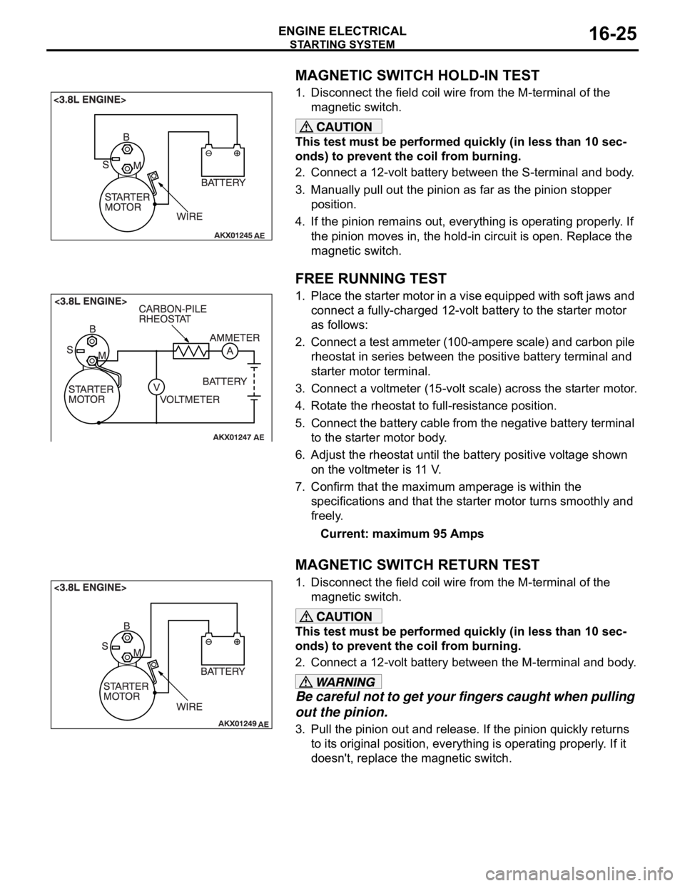
1. Disconnect the field coil wire from the M-terminal of the
magnetic switch.
This test must be performed quickly (in less than 10 sec-
onds) to prevent the coil from burning.
2. Connect a 12-volt battery between the S-terminal and body.
3. Manually pull out the pinion as far as the pinion stopper
position.
4. If the pinion remains out, everything is operating properly. If
the pinion moves in, the hold-in circuit is open. Replace the
magnetic switch.
.
FREE RUNNING TEST
1. Place the starter motor in a vise equipped with soft jaws and
connect a fully-charged 12-volt battery to the starter motor
as follows:
2. Connect a test ammeter (100-ampere scale) and carbon pile
rheostat in series between the positive battery terminal and
starter motor terminal.
3. Connect a voltmeter (15-volt scale) across the starter motor.
4. Rotate the rheostat to full-resistance position.
5. Connect the battery cable from the negative battery terminal
to the starter motor body.
6. Adjust the rheostat until the battery positive voltage shown
on the voltmeter is 11 V.
7. Confirm that the maximum amperage is within the
specifications and that the starter motor turns smoothly and
freely.
Current: maximum 95 Amps
.
MAGNETIC SWITCH RETURN TEST
1. Disconnect the field coil wire from the M-terminal of the
magnetic switch.
This test must be performed quickly (in less than 10 sec-
onds) to prevent the coil from burning.
2. Connect a 12-volt battery between the M-terminal and body.
Be careful not to get your fingers caught when pulling
out the pinion.
3. Pull the pinion out and release. If the pinion quickly returns
to its original position, everything is operating properly. If it
doesn't, replace the magnetic switch.
Page 1003 of 1500
Page 1004 of 1500
Page 1085 of 1500
WINDOW GLASS
BODY42-18
INSTALLATION SERVICE POINTS
.
>>A<< WINDSHIELD SPACER/GLASS STOP-
PER/WINDSHIELD UPPER MOLDING/WIND-
SHIELD SIDE MOLDING INSTALLATION
Leave the degreased parts for 3 or more minutes to dry
well, before starting on the next step. Do not touch the
degreased parts.
1. Use 3M
AAD Part number 8906 or equivalent to degrease
the inside and outside of the windshield and the body
flanges.
2. Install the windshield spacer and glass stoppers to the
specified positions so that there are no adrift or warped
surfaces inside the windshield.
3. Install the windshield upper and side moldings to the
windshield.
.