2005 MITSUBISHI 380 set clock
[x] Cancel search: set clockPage 1026 of 1500

CROSSMEMBER
POWER PLANT MOUNT32-9
CROSSMEMBER
REMOVAL AND INSTALLATIONM1321003200551
Before removing the steering wheel and air bag module assembly, always refer to GROUP 52B -
Service Precautions (P.52B-16), Air bag Module and Clock Spring (P.52B-237). Also, set the front
wheels so that they are facing straight forward, and remove the ignition key. If you fail to do this,
the SRS clock spring will be damaged, causing the SRS air bag to be inoperative and serious
injury.
*1: Indicates parts which should be initially tightened, and then fully tightened after placing the
vehicle horizontally and loading the full weight of the engine on the vehicle body.
*2: Indicates parts which should be temporarily tightened, and then fully tightened with the vehicle
on the ground in the unladen condition.
Pre-removal Operation
Power Steering Fluid Draining (Refer to GROUP 37,
On-vehicle Service Fluid Replacement P.37-18).
Power Steering Hoses Removal and Installation (Refer to
GROUP 37, Power Steering Hoses P.37A-57).
Air Bag Module and Steering Wheel Assembly Removal
(Refer to GROUP 37, Steering Wheel P.37-23).
Clock Spring Removal (Refer to GROUP 52B, Air Bag
Module and Clock Spring P.52B-237).
Floor Console Assembly Removal (Refer to GROUP 52A,
Floor Console Assembly P.52A-10).
Front Scuff Plate (LH) and Cowl Side Trim (LH) Removal
(Refer to GROUP 52A, Trims P.52A-11).
Trunk Lid Release Handle Cover Removal (Refer to
GROUP 42, Trunk Lid P.42-63).
Accelerator Stopper Removal (Refer to GROUP 17,
Accelerator Pedal P.17-9).
Front Floor Carpet Removal
Centremember Removal (Refer to P.32-7).Post-installation Operation
Centremember Installation (Refer to P.32-7).
Front Floor Carpet Installation
Accelerator Stopper Installation (Refer to GROUP 17,
Accelerator Pedal P.17-9).
Trunk Lid Release Handle Cover Installation (Refer to
GROUP 42, Trunk Lid P.42-63).
Front Scuff Plate (LH) and Cowl Side Trim (LH) Installa-
tion (Refer to GROUP 52A, Trims P.52A-11).
Floor Console Assembly Installation (Refer to GROUP
52A, Floor Console Assembly P.52A-10).
Clock Spring Installation (Refer to GROUP 52B, Air Bag
Module and Clock Spring P.52B-237).
Steering Wheel Assembly and Air Bag Module Installation
(Refer to P.37-23).
Check the dust cover for cracks or damage by pushing it
with your finger.
Power Steering Fluid Supplying (Refer to GROUP 37,
On-vehicle Service Fluid Replacement P.37-18).
Power Steering Fluid Line Bleeding (Refer to P.37-18).
Checking Steering Wheel Position with Wheels Straight
Ahead.
Front Wheel Alignment Adjustment (Refer to GROUP 33,
On-vehicle Service
Front Wheel Alignment Check and
Adjustment P.33-6).
Page 1268 of 1500

MAINTENANCE SERVICE
GENERAL00-47
6. Securely insert the dipstick.
NOTE: The transmission fluid should always be replaced
under the following conditions:
.
When troubleshooting the transaxle.
When overhauling the transaxle.
When the transmission fluid is noticeably dirty or burnt
(driving under severe conditions).
TRANSMISSION FLUID CHANGE
Refer to GROUP 23A, Automatic Transmission - On-vehicle
Service P.23A-296.
12. ENGINE COOLANT (CHANGE)M1001003100357
Check the cooling system parts such as the radiator, heater
and oil cooler hoses, thermostat and their connections for leak-
age and damage.
.
CHANGING COOLANT
1. Set the temperature control knob to the "HOT" position.
2. Run the engine until the engine coolant warms, and then
stop the engine.
When removing the radiator cap, use care to avoid
contact with hot coolant or steam. Place a shop towel
over the cap and turn the cap counterclockwise a lit-
tle to let the pressure escape through the vinyl tube.
After relieving the steam pressure, remove the cap by
slowly turning it counterclockwise.
3. Drain the water from the radiator, heater core and engine
after unplugging the radiator drain plug and removing the
radiator cap.
Page 1352 of 1500

AUTO-CRUISE CONTROL
ENGINE AND EMISSION CONTROL17-21
CIRCUIT OPERATION
This circuit judges the signals of each switch
("COAST/SET", "ACC/RES" and "CANCEL") of the
auto-cruise control switch. The Engine ECU detects
the state of the auto-cruise control switch by sensing
the voltages shown below.
When all switches are OFF: 4.7 5.0 volts
When the "CRUISE" (MAIN) switch is "ON": 0
0.3 volt
When the "COAST/SET" switch is ON: 2.0 2.8
volts
When the "ACC/RES" switch is ON: 3.3 4.1
volts
When the "CANCEL" switch is ON: 0.8 1.5 volts
.
DTC SET CONDITIONS
Check Condition
The "CRUISE" indicator lamp illuminates.Judgement Criteria
If the auto-cruise control switch is operated, this
DTC will be set when the Engine ECU terminal
voltage is different from the standard value.
.
TROUBLESHOOTING HINTS (THE MOST
LIKELY CAUSES FOR THIS CASE:)
Malfunction of the auto-cruise control switch.
Malfunction of the clock spring.
Damaged harness or connector.
Malfunction of the Engine ECU.
Circuit drawings
Refer to circuit diagrams GROUP-90
Refer to configuration diagrams GROUP-80
Refer to component locations GROUP-70
DIAGNOSIS
Required Special Tools:
MB991958: Diagnostic Tool (MUT-III Sub Assembly)
MB991824: V.C.I.
MB991827: MUT-III USB Cable
MB991910: MUT-III Main Harness A
MB991223: Harness Set
MB992044: ENGINE-ECU Check Harness
Page 1363 of 1500

AUTO-CRUISE CONTROL
ENGINE AND EMISSION CONTROL17-32
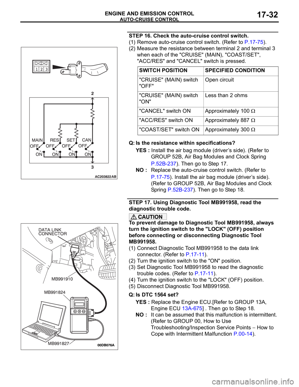
STEP 16. Check the auto-cruise control switch.
(1) Remove auto-cruise control switch. (Refer to P.17-75).
(2) Measure the resistance between terminal 2 and terminal 3
when each of the "CRUISE" (MAIN), "COAST/SET",
"ACC/RES" and "CANCEL" switch is pressed.
Q: Is the resistance within specifications?
YES : Install the air bag module (driver’s side). (Refer to
GROUP 52B, Air Bag Modules and Clock Spring
P.52B-237). Then go to Step 17.
NO : Replace the auto-cruise control switch. (Refer to
P.17-75). Install the air bag module (driver’s side).
(Refer to GROUP 52B, Air Bag Modules and Clock
Spring P.52B-237). Then go to Step 18.
STEP 17. Using Diagnostic Tool MB991958, read the
diagnostic trouble code.
To prevent damage to Diagnostic Tool MB991958, always
turn the ignition switch to the "LOCK" (OFF) position
before connecting or disconnecting Diagnostic Tool
MB991958.
(1) Connect Diagnostic Tool MB991958 to the data link
connector. (Refer to P.17-11).
(2) Turn the ignition switch to the "ON" position.
(3) Set Diagnostic Tool MB991958 to read the diagnostic
trouble codes. (Refer to P.17-11).
(4) Turn the ignition switch to the "LOCK" (OFF) position.
(5) Disconnect Diagnostic Tool MB991958.
Q: Is DTC 1564 set?
YES : Replace the Engine ECU.[Refer to GROUP 13A,
Engine ECU 13A-675] . Then go to Step 18.
NO : It can be assumed that this malfunction is intermittent.
(Refer to GROUP 00, How to Use
Troubleshooting/Inspection Service Points
How to
Cope with Intermittent Malfunction P.00-14). SWITCH POSITION SPECIFIED CONDITION
"CRUISE" (MAIN) switch
"OFF"Open circuit
"CRUISE" (MAIN) switch
"ON"Less than 2 ohms
"CANCEL" switch ON Approximately 100
"ACC/RES" switch ON Approximately 887
"COAST/SET" switch ON Approximately 300