2005 MITSUBISHI 380 Car seat
[x] Cancel search: Car seatPage 398 of 1500

SYMPTOM PROCEDURES
SIMPLIFIED WIRING SYSTEM (SWS)54B-398
INSPECTION PROCEDURE K-7: Interior Light: The seat belt warning lamp do not illuminate or go out
normally
NOTE: This troubleshooting procedure requires the
use of diagnostic tool MB991958 and SWS monitor
kit MB991813. For details on how to use the SWS
monitor, refer to "How to connect SWS monitor
P.54B-13."
.
CIRCUIT OPERATION
The combination meter and the ETACS-ECU illumi-
nates and flashes the seat belt warning lamp by
using the signal from the seat belt switch, the ignition
switch (IG1) and the vehicle speed signal.
.
TECHNICAL DESCRIPTION (COMMENT)
If the seat belt warning lamp does not illuminate or
flash correctly, connector(s), wiring harness in the
CAN bus lines, the door switches, the ETACS-ECU,
or the combination meter may be defective.
.
TROUBLESHOOTING HINTS
Refer to circuit diagrams GROUP-90
Refer to configuration diagrams GROUP-80
Trouble in input signal system
The wiring harness or connectors may have
loose, corroded, or damaged terminals, or termi-
nals pushed back in the connector
The combination meter may be defective
The ETACS-ECU may be defective
DIAGNOSIS
Required Special Tools:
MB991223: Harness Set
MB991958: Diagnostic Tool (MUT-III Sub Assembly)
MB991824: Vehicle Communication Interface (V.C.I.)
MB991827: MUT-III USB Cable
MB991910: MUT-III Main Harness A
MB991813: SWS Monitor Kit
MB991806: SWS Monitor Cartridge
MB991812: SWS Monitor Harness (For Column-ECU)
MB991822: Test Probe Harness
Page 876 of 1500

DUCTS
HEATER, AIR CONDITIONING AND VENTILATION55-175
DUCTS
REMOVAL AND INSTALLATIONM1553001000275
DEFROSTER NOZZLE AND
DISTRIBUTION DUCT REMOVAL
STEPS
INSTRUMENT PANEL (REFER TO
GROUP 52A P.52A-4).
1. VENTILATOR AIR DISTRIBUTION
DUCT
2. SIDE DEFROSTER DUCT
3. DEFROSTER NOZZLE
FOOT DUCT AND REAR HEATER
DUCT REMOVAL STEPS
FRONT SEAT ASSEMBLY
(REFER TO GROUP 52A, FRONT
SEAT ASSEMBLY P.52A-21).
FRONT SCUFF PLATE, COWL
SIDE TRIM (REFER TO GROUP
52A, TRIMS P.52A-11.)
FLOOR CARPET PEELING
FLOOR CONSOLE ASSEMBLY
(REFER TO GROUP 52A, FLOOR
CONSOLE ASSEMBLY P.52A-10.)
TRUNK LID RELEASE HANDLE
COVER (REFER TO GROUP 42,
TRUNK LID P.42-63.)
ACCELERATOR STOPPER
(REFER TO GROUP 17,
ACCELERATOR CABLE AND
PEDAL P.17-9.)
4. REAR HEATER DUCT A
5. REAR HEATER DUCT BFOOT DUCT AND REAR HEATER
DUCT REMOVAL STEPS
Page 961 of 1500

GENERAL DESCRIPTION
INTAKE AND EXHAUST15-2
GENERAL DESCRIPTIONM1151000100446
The exhaust pipe is divided into four parts.
INTAKE AND EXHAUST DIAGNOSIS
INTRODUCTIONM1151006900321
Intake leaks usually create driveability issues that
are not obviously related to the intake system.
Exhaust leaks or abnormal noise is caused by
cracks, gaskets and fittings, or by exhaust pipe or
muffler damage due to impacts during travel. The
exhaust leaks from these sections and causes the
exhaust noise to increase. There may be cases
when the system contacts the body and vibration
noise is generated.
TROUBLESHOOTING STRATEGYM1151007000321
Use these steps to plan your diagnostic strategy. If
you follow them carefully, you will be sure that you
have exhausted most of the possible ways to find an
intake or exhaust system fault.
1. Gather information from the customer.2. Verify that the condition described by the
customer exists.
3. Find the malfunction by following the Symptom
Chart.
4. Verify malfunction is eliminated.
SYMPTOM CHARTM1151007100328
SYMPTOM PROCEDURES
INSPECTION PROCEDURE 1: Exhaust Leakage
DIAGNOSIS
STEP 1. Start the engine. Have an assistant stay
in the driver’s seat. Raise the vehicle on a hoist.
Have the assistant rev the engine while
searching for exhaust leaks.
Q: Is the exhaust leaking?
YES :
Go to Step 2.
NO : The procedure is complete.
STEP 2. Check the gasket for cracks, damage.
Q: Is the gasket damaged?
YES :
Replace the gasket, then go Step 1.
NO : Go to Step 3.
STEP 3. Check for loose coupling sections.
Q: Are there any loose each sections?
YES :
Tighten, then go to Step 1.
NO : There is no action to be taken. SYMPTOM INSPECTION PROCEDURE REFERENCE PAGE
Exhaust Leakage 1
P.15-2
Abnormal Noise 2
P.15-3
Page 1186 of 1500
ON-VEHICLE SERVICE
BASIC BRAKE SYSTEM35A-21
After a new brake disc is installed, always grind the
brake disc with an on-the-car type brake lathe. If this
step is not carried out, the brake disc run-out exceeds
the specified value, resulting in judder.
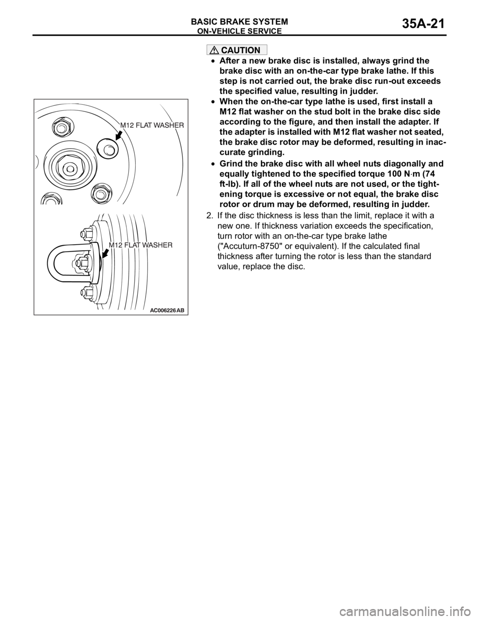
When the on-the-car type lathe is used, first install a
M12 flat washer on the stud bolt in the brake disc side
according to the figure, and then install the adapter. If
the adapter is installed with M12 flat washer not seated,
the brake disc rotor may be deformed, resulting in inac-
curate grinding.
Grind the brake disc with all wheel nuts diagonally and
equally tightened to the specified torque 100 N
m (74
ft-lb). If all of the wheel nuts are not used, or the tight-
ening torque is excessive or not equal, the brake disc
rotor or drum may be deformed, resulting in judder.
2. If the disc thickness is less than the limit, replace it with a
new one. If thickness variation exceeds the specification,
turn rotor with an on-the-car type brake lathe
("Accuturn-8750" or equivalent). If the calculated final
thickness after turning the rotor is less than the standard
value, replace the disc.
.
Page 1188 of 1500
ON-VEHICLE SERVICE
BASIC BRAKE SYSTEM35A-23
After a new brake disc is installed, always grind the
brake disc with an on-the-car type brake lathe. If this
step is not carried out, the brake disc run-out exceeds
the specified value, resulting in judder.
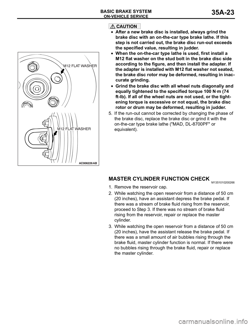
When the on-the-car type lathe is used, first install a
M12 flat washer on the stud bolt in the brake disc side
according to the figure, and then install the adapter. If
the adapter is installed with M12 flat washer not seated,
the brake disc rotor may be deformed, resulting in inac-
curate grinding.
Grind the brake disc with all wheel nuts diagonally and
equally tightened to the specified torque 100 N
m (74
ft-lb). If all of the wheel nuts are not used, or the tight-
ening torque is excessive or not equal, the brake disc
rotor or drum may be deformed, resulting in judder.
5. If the run-out cannot be corrected by changing the phase of
the brake disc, replace the brake disc or grind it with the
on-the-car type brake lathe ("MAD, DL-8700PF" or
equivalent).
MASTER CYLINDER FUNCTION CHECKM1351010200266
1. Remove the reservoir cap.
2. While watching the open reservoir from a distance of 50 cm
(20 inches), have an assistant depress the brake pedal. If
there was a stream of brake fluid rising from the reservoir,
proceed to Step 3. If there was no stream of brake fluid
rising from the reservoir, repair or replace the master
cylinder.
3. While watching the open reservoir from a distance of 50 cm
(20 inches), have the assistant release the brake pedal. If
there was a small amount of air bubbles rising through the
brake fluid, master cylinder function is normal. If there were
no bubbles rising through the brake fluid, repair or replace
the master cylinder.
Page 1210 of 1500
ON-VEHICLE SERVICE
PARKING BRAKES36-3
SYMPTOM PROCEDURES
INSPECTION PROCEDURE 1: Insufficient Parking Brake Function
DIAGNOSIS
STEP 1. Check the excessive parking brake lever
stroke.
Refer to P.36-3.
Q: Is the parking brake lever stroke adjusted
properly?
YES :
Go to Step 2.
NO : Adjust the parking brake lever stroke or
check the parking brake cable routing. Then
go to Step 5.
STEP 2. Check the parking brake cable for
sticking.
Q: Is the parking brake cable stuck?
YES :
Replace the cable. Then go to Step 5.
NO : Go to Step 3.
STEP 3. Check the brake lining and brake drum
for wear.
Refer to P.36-11.
Q: Is the brake lining thickness or brake drum inside
diameter outside of specification?
YES :
Replace the rear brake shoe assembly or
rear brake disc (Refer to P.36-8). Then go to
Step 5.
NO : Go to Step 4.
STEP 4. Check for oil, water, etc., on the lining
contact surfaces.
Q: Is oil, water, etc., on the lining contact surface?
YES :
Replace the part and determine and repair
source/cause of foreign material. Then go to
St e p 5.
NO : Carry out the parking brake lining seating
(Refer to P.36-5) and then go to Step 5.
STEP 5. Retest the system.
Q: Is the malfunction eliminated?
YES :
The procedure is complete.
NO : Recheck from Step 1.
ON-VEHICLE SERVICE
PARKING BRAKE LEVER STROKE CHECK AND
ADJUSTMENT
M1361000900362
1. Pull the parking brake lever with a force of approximately
200 N (45 pounds) and count the number of notches.
Standard value: 5
7 notches
2. If the parking brake lever stroke is not within the standard
value, adjust as described below.
(1) Release the parking brake.
Page 1212 of 1500
ON-VEHICLE SERVICE
PARKING BRAKES36-5
PARKING BRAKE SWITCH CHECKM1361003300411
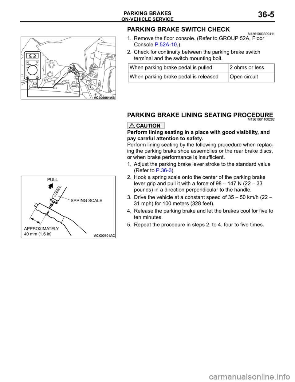
1. Remove the floor console. (Refer to GROUP 52A, Floor
Console P.52A-10.)
2. Check for continuity between the parking brake switch
terminal and the switch mounting bolt.
PARKING BRAKE LINING SEATING PROCEDUREM1361001100262
Perform lining seating in a place with good visibility, and
pay careful attention to safety.
Perform lining seating by the following procedure when replac-
ing the parking brake shoe assemblies or the rear brake discs,
or when brake performance is insufficient.
1. Adjust the parking brake lever stroke to the standard value
(Refer to P.36-3).
2. Hook a spring scale onto the center of the parking brake
lever grip and pull it with a force of 98
147 N (22 33
pounds) in a direction perpendicular to the handle.
3. Drive the vehicle at a constant speed of 35
50 km/h (22
31 mph) for 100 meters (328 feet).
4. Release the parking brake and let the brakes cool for five to
ten minutes.
5. Repeat the procedure in steps 2. to 4. four to five times.When parking brake pedal is pulled 2 ohms or less
When parking brake pedal is released Open circuit
Page 1242 of 1500
VEHICLE IDENTIFICATION
GENERAL00-21
OPTION CODES (380 Series)
EXPORT CODES
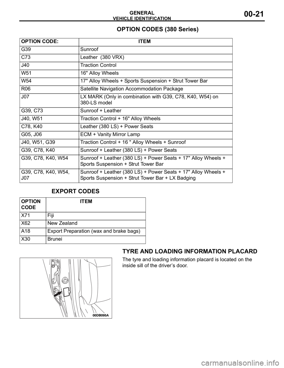
TYRE AND LOADING INFORMATION PLACARD
The tyre and loading information placard is located on the
inside sill of the driver’s door. OPTION CODE: ITEM
G39 Sunroof
C73 Leather (380 VRX)
J40 Traction Control
W51 16" Alloy Wheels
W54 17" Alloy Wheels + Sports Suspension + Strut Tower Bar
R06 Satellite Navigation Accommodation Package
J07 LX MARK (Only in combination with G39, C78, K40, W54) on
380-LS model
G39, C73 Sunroof + Leather
J40, W51 Traction Control + 16" Alloy Wheels
C78, K40 Leather (380 LS) + Power Seats
G05, J06 ECM + Vanity Mirror Lamp
J40, W51, G39 Traction Control + 16 " Alloy Wheels + Sunroof
G39, C78, K40 Sunroof + Leather (380 LS) + Power Seats
G39, C78, K40, W54 Sunroof + Leather (380 LS) + Power Seats + 17" Alloy Wheels +
Sports Suspension + Strut Tower Bar
G39, C78, K40, W54,
J07Sunroof + Leather (380 LS) + Power Seats + 17" Alloy Wheels +
Sports Suspension + Strut Tower Bar + LX Badging
OPTION
CODE ITEM
X71 Fiji
X62 New Zealand
A18 Export Preparation (wax and brake bags)
X30 Brunei