Page 254 of 1500
SYMPTOM PROCEDURES
SIMPLIFIED WIRING SYSTEM (SWS)54B-254
STEP 5. Check the windshield washer motor.
(1) Disconnect windshield washer motor connector A-29, and
check at windshield washer motor connector side.
(2) Fill the windshield washer tank with washer fluid.
(3) When battery voltage is applied between terminals 1 and 2,
washer fluid should spray out.
Q: Does the windshield washer motor operate normally?
YES : Go to Step 6.
NO : Replace the windshield washer motor. Verify that the
windshield washer works normally.
Page 1034 of 1500

51-1
GROUP 51
EXTERIOR
CONTENTS
FRONT BUMPER ASSEMBLY . . . . .51-2
REMOVAL AND INSTALLATION . . . . . . . . 51-2
DISASSEMBLY AND ASSEMBLY . . . . . . . 51-3
REAR BUMPER ASSEMBLY . . . . . .51-5
REMOVAL AND INSTALLATION . . . . . . . . 51-5
RADIATOR GRILLE. . . . . . . . . . . . . .51-6
REMOVAL AND INSTALLATION . . . . . . . . 51-6
GARNISHES AND MOLDINGS . . . . .51-7
SPECIAL TOOLS . . . . . . . . . . . . . . . . . . . . 51-7
MOLDINGS . . . . . . . . . . . . . . . . . . . . . . . . . 51-8
REMOVAL AND INSTALLATION . . . . . . . . 51-8
REAR SPOILER . . . . . . . . . . . . . . . . .51-11
REMOVAL AND INSTALLATION . . . . . . . . 51-11
MUD GUARD . . . . . . . . . . . . . . . . . . .51-12
REMOVAL AND INSTALLATION . . . . . . . . 51-12
UNDER COVER . . . . . . . . . . . . . . . . .51-13
REMOVAL AND INSTALLATION . . . . . . . . 51-13
WINDSHIELD WIPER AND WASHER51-14
GENERAL DESCRIPTION . . . . . . . . . . . . . 51-14
WINDSHIELD WIPER AND WASHER DIAGNOSIS . . . . . . . . . . . . . . . . . . . . . . . . . 51-14
SPECIAL TOOLS . . . . . . . . . . . . . . . . . . . . 51-15
ON-VEHICLE SERVICE . . . . . . . . . . . . . . . 51-15
WINDSHIELD INTERMITTENT WIPER
VOLUME CHECK . . . . . . . . . . . . . . . . . . . . 51-15
WINDSHIELD WASHER FLUID EJECTION
CHECK . . . . . . . . . . . . . . . . . . . . . . . . . . . . 51-16
WINDSHIELD WIPER . . . . . . . . . . . . . . . . . 51-17
REMOVAL AND INSTALLATION . . . . . . . . 51-17
INSPECTION. . . . . . . . . . . . . . . . . . . . . . . . 51-20
WINDSHIELD WASHER . . . . . . . . . . . . . . . 51-23
REMOVAL AND INSTALLATION . . . . . . . . 51-23
INSPECTION. . . . . . . . . . . . . . . . . . . . . . . . 51-24
MARK . . . . . . . . . . . . . . . . . . . . . . . . .51-25
REMOVAL AND INSTALLATION . . . . . . . . 51-25
DOOR MIRROR . . . . . . . . . . . . . . . . .51-27
GENERAL DESCRIPTION . . . . . . . . . . . . . 51-27
DOOR MIRROR . . . . . . . . . . . . . . . . . . . . . 51-28
REMOVAL AND INSTALLATION . . . . . . . . 51-28
INSPECTION. . . . . . . . . . . . . . . . . . . . . . . . 51-29
SPECIFICATIONS . . . . . . . . . . . . . . .51-31
FASTENER TIGHTENING SPECIFICATIONS51-31
SERVICE SPECIFICATIONS . . . . . . . . . . . 51-31
ADHESIVE . . . . . . . . . . . . . . . . . . . . . . . . . 51-31
Page 1049 of 1500

WINDSHIELD WIPER AND WASHER
EXTERIOR51-16
If the windshield intermittent wiper interval control is operated,
the wiper interval should change.
To prevent damage to diagnostic tool, always turn the igni-
tion switch to the "LOCK" (OFF) position before connect-
ing or disconnecting.
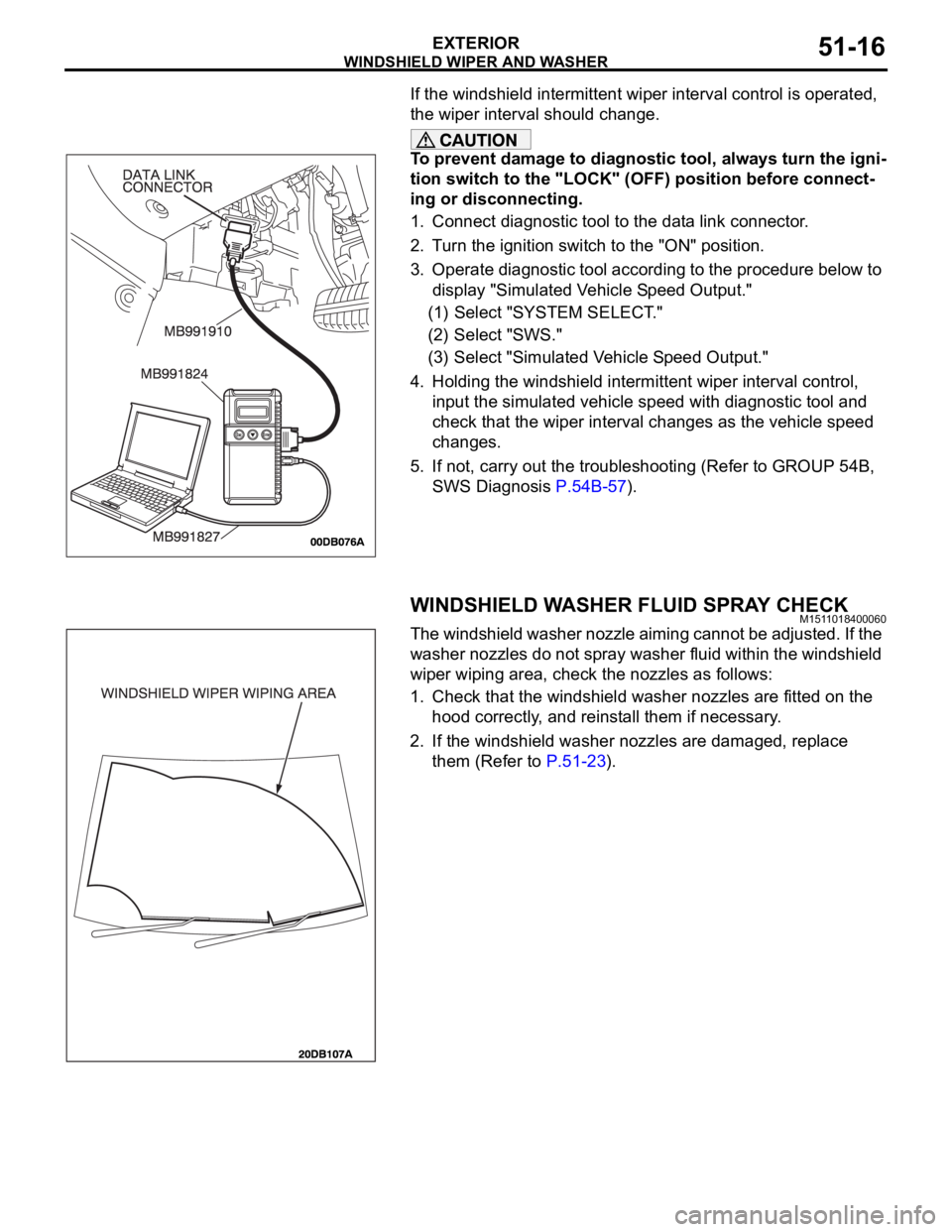
1. Connect diagnostic tool to the data link connector.
2. Turn the ignition switch to the "ON" position.
3. Operate diagnostic tool according to the procedure below to
display "Simulated Vehicle Speed Output."
(1) Select "SYSTEM SELECT."
(2) Select "SWS."
(3) Select "Simulated Vehicle Speed Output."
4. Holding the windshield intermittent wiper interval control,
input the simulated vehicle speed with diagnostic tool and
check that the wiper interval changes as the vehicle speed
changes.
5. If not, carry out the troubleshooting (Refer to GROUP 54B,
SWS Diagnosis P.54B-57).
WINDSHIELD WASHER FLUID SPRAY CHECKM1511018400060
The windshield washer nozzle aiming cannot be adjusted. If the
washer nozzles do not spray washer fluid within the windshield
wiper wiping area, check the nozzles as follows:
1. Check that the windshield washer nozzles are fitted on the
hood correctly, and reinstall them if necessary.
2. If the windshield washer nozzles are damaged, replace
them (Refer to P.51-23).
Page 1188 of 1500

ON-VEHICLE SERVICE
BASIC BRAKE SYSTEM35A-23
After a new brake disc is installed, always grind the
brake disc with an on-the-car type brake lathe. If this
step is not carried out, the brake disc run-out exceeds
the specified value, resulting in judder.
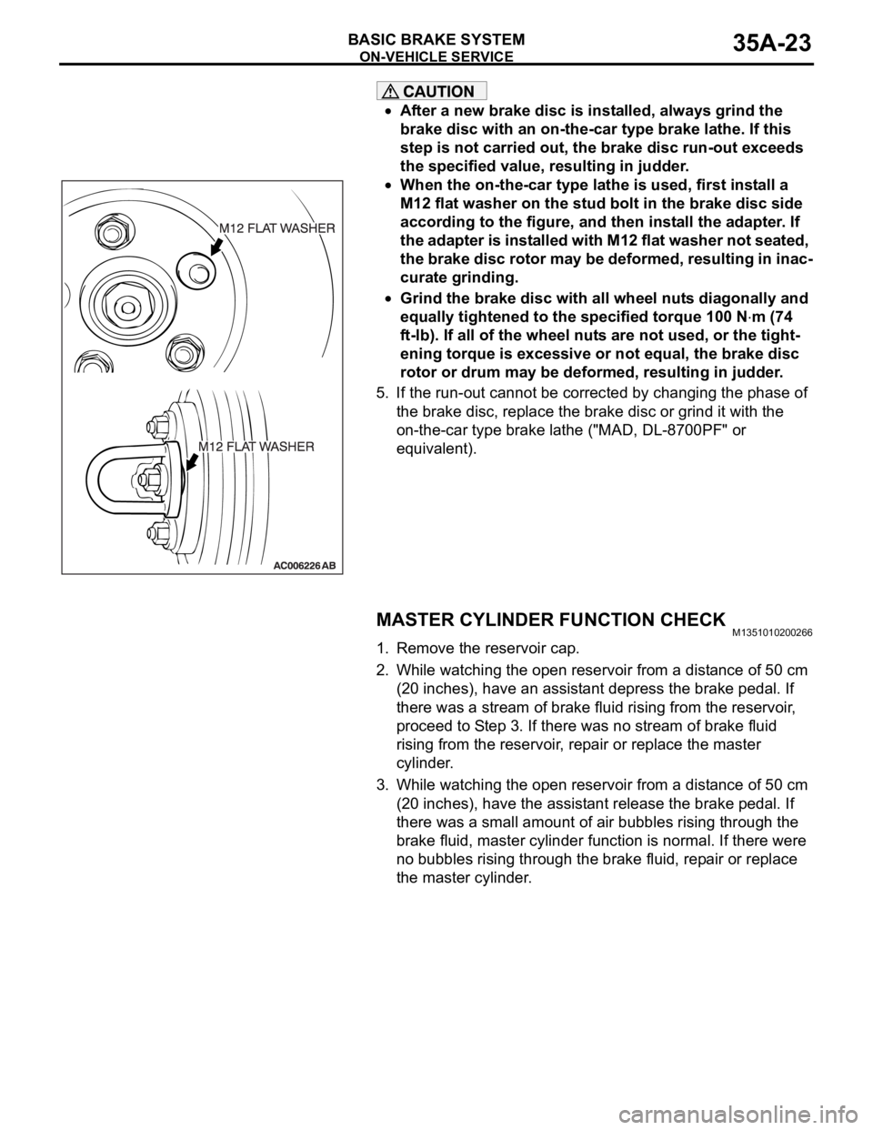
When the on-the-car type lathe is used, first install a
M12 flat washer on the stud bolt in the brake disc side
according to the figure, and then install the adapter. If
the adapter is installed with M12 flat washer not seated,
the brake disc rotor may be deformed, resulting in inac-
curate grinding.
Grind the brake disc with all wheel nuts diagonally and
equally tightened to the specified torque 100 N
m (74
ft-lb). If all of the wheel nuts are not used, or the tight-
ening torque is excessive or not equal, the brake disc
rotor or drum may be deformed, resulting in judder.
5. If the run-out cannot be corrected by changing the phase of
the brake disc, replace the brake disc or grind it with the
on-the-car type brake lathe ("MAD, DL-8700PF" or
equivalent).
MASTER CYLINDER FUNCTION CHECKM1351010200266
1. Remove the reservoir cap.
2. While watching the open reservoir from a distance of 50 cm
(20 inches), have an assistant depress the brake pedal. If
there was a stream of brake fluid rising from the reservoir,
proceed to Step 3. If there was no stream of brake fluid
rising from the reservoir, repair or replace the master
cylinder.
3. While watching the open reservoir from a distance of 50 cm
(20 inches), have the assistant release the brake pedal. If
there was a small amount of air bubbles rising through the
brake fluid, master cylinder function is normal. If there were
no bubbles rising through the brake fluid, repair or replace
the master cylinder.
Page 1256 of 1500
RECOMMENDED LUBRICANTS AND LUBRICANT CAPACITIES TABLE
GENERAL00-35
RECOMMENDED LUBRICANTS AND LUBRICANT
CAPACITIES TABLE
M1001001300504
RECOMMENDED LUBRICANTS
LUBRICANT CAPACITY TABLE
<3.8L ENGINE>LUBRICANT SPECIFICATION
Engine oil Engine oils conforming to ACEA A1, A2 or A3 and
AP1 SG or higher
AutomaticTransmission fluid Genuine Mitsubishi Motors ATF-SP III
Manual Transmission fluid Genuine Mitsubishi Motors MTF
Power steering fluid ATF DEXRON III or DEXRON II
Brakes fluid Conforming to DOT 3 or DOT 4
Engine coolant Genuine Mitsubishi Motors coolant
Refrigerant (air conditioning) HFC-134a
DESCRIPTION SPECIFICATION
Engine oil (Litres) Oil pan (excluding oil filter) 4.0
Oil filter 0.3
Engine coolant (Litres) 8.7
Automatic Transmission fluid (Litres) 8.4
Manual Transmission fluid (Litres) 2.8
Power steering fluid (Litres) 1.2
Fuel tank (Litres) 67.0
Washer fluid (Litres) 5.0
Refrigerant (air conditioning) (grams) 435g - 475g