2005 MITSUBISHI 380 air filter
[x] Cancel search: air filterPage 704 of 1500

GENERAL DESCRIPTION
HEATER, AIR CONDITIONING AND VENTILATION55-3
GENERAL DESCRIPTIONM1552000100351
The heater and cooling units are combined in a sin-
gle unit, which, with the mode film damper and flow
rate control valve in the heater unit, reduces ventila-
tion resistance, increases fan power, and decreases
noise.
SAFETY PRECAUTIONS
Wear safety goggles and gloves when servic-
ing the refrigeration system to prevent
severe damage to eyes and hands.
Because R-134a refrigerant is a hydro fluorocarbon
(HFC) which contains hydrogen atoms in place of
chlorine atoms, it will not cause damage to the ozone
layer.
Ozone filters out harmful radiation from the sun. To
assist in protecting the ozone layer, Mitsubishi
Motors Corporation recommends an R-134a refriger-
ant recycling device.
Refrigerant R-134a is transparent and colorless in
both the liquid and vapor state. Since it has a boiling
point of
29.8C (21.64F) at atmospheric pressure,
it will be a vapor at all normal temperatures and pres-
sures. The vapor is heavier than air, non-flammable,
and non-explosive. The following precautions must
be observed when handling R-134a.
Do not heat R-134a above 40C (104.0F) or it
may catch fire and explode.
R-134a evaporates so rapidly at normal atmospheric
pressures and temperatures that it tends to freeze
anything it contacts. For this reason, extreme care
must be taken to prevent any liquid refrigerant from
contacting the skin and especially the eyes. Always
wear safety goggles when servicing the refrigeration
part of the A/C system. Keep a bottle of sterile min-
eral oil handy when working on the refrigeration sys-
tem.1. If any liquid refrigerant gets into your eyes, use a
few drops of mineral oil to wash them out. R-134a
is rapidly absorbed by the oil.
2. Next, splash your eyes with plenty of cold water.
3. Call your doctor immediately even if irritation has
ceased.
Keep R-134a containers upright when charging
the system.
In most instances, moderate heat is required to bring
the pressure of the refrigerant in its container above
the pressure of the system when charging or adding
refrigerant.
A bucket or large pan of hot water not over 40
C
(104.0
F) is all the heat required for this purpose. Do
not heat the refrigerant container with a blow torch or
any other means that would raise temperature and
pressure above this temperature. Do not weld or
steam-clean on or near the system components or
refrigerant lines.
A leak detector for R-134a should be used to
check for refrigerant gas leaks.
Do not allow liquid refrigerant to touch bright
metal or it will be stained.
When metering R-134a into the refrigeration system,
keep the supply tank or cans in an upright position. If
the refrigerant container is on its side or upside
down, liquid refrigerant will enter the system and
damage the compressor.
Refrigerant will tarnish bright metal and chrome sur-
faces, and in combination with moisture can severely
corrode all metal surfaces. ITEM SPECIFICATION
Heater control assembly Dial type
Compressor 10S17
Compressor Model Swashplate type
Refrigerant and quantity (g) R-134a (HFC-134a), 435
475
Page 846 of 1500

ON-VEHICLE SERVICE
HEATER, AIR CONDITIONING AND VENTILATION55-145
LOST CHARGE
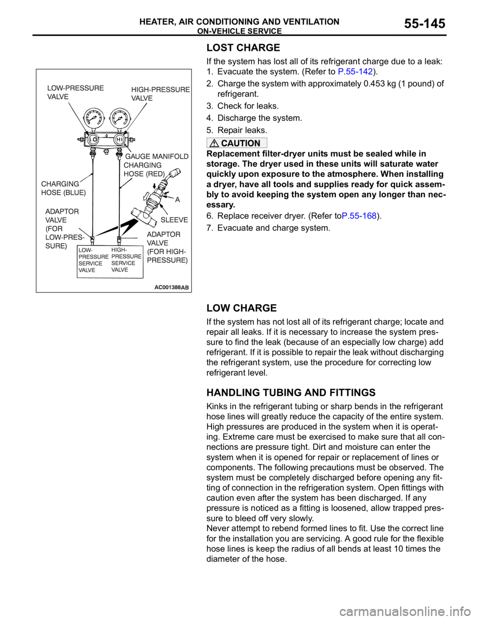
If the system has lost all of its refrigerant charge due to a leak:
1. Evacuate the system. (Refer to P.55-142).
2. Charge the system with approximately 0.453 kg (1 pound) of
refrigerant.
3. Check for leaks.
4. Discharge the system.
5. Repair leaks.
Replacement filter-dryer units must be sealed while in
storage. The dryer used in these units will saturate water
quickly upon exposure to the atmosphere. When installing
a dryer, have all tools and supplies ready for quick assem-
bly to avoid keeping the system open any longer than nec-
essary.
6. Replace receiver dryer. (Refer toP.55-168).
7. Evacuate and charge system.
LOW CHARGE
If the system has not lost all of its refrigerant charge; locate and
repair all leaks. If it is necessary to increase the system pres-
sure to find the leak (because of an especially low charge) add
refrigerant. If it is possible to repair the leak without discharging
the refrigerant system, use the procedure for correcting low
refrigerant level.
HANDLING TUBING AND FITTINGS
Kinks in the refrigerant tubing or sharp bends in the refrigerant
hose lines will greatly reduce the capacity of the entire system.
High pressures are produced in the system when it is operat-
ing. Extreme care must be exercised to make sure that all con-
nections are pressure tight. Dirt and moisture can enter the
system when it is opened for repair or replacement of lines or
components. The following precautions must be observed. The
system must be completely discharged before opening any fit-
ting of connection in the refrigeration system. Open fittings with
caution even after the system has been discharged. If any
pressure is noticed as a fitting is loosened, allow trapped pres-
sure to bleed off very slowly.
Never attempt to rebend formed lines to fit. Use the correct line
for the installation you are servicing. A good rule for the flexible
hose lines is keep the radius of all bends at least 10 times the
diameter of the hose.
Page 869 of 1500

Page 1223 of 1500

GENERAL00-2
MAINTENANCE SERVICE . . . . . . . .00-37
1. FUEL SYSTEM (TANK, PIPE LINE AND
CONNECTION, AND FUEL TANK FILLER
TUBE CAP) (CHECK FOR LEAKS) . . . . . . 00-37
2. FUEL HOSES (CHECK CONDITION) . . 00-37
3. AIR CLEANER FILTER (REPLACE). . . . 00-37
4. EVAPORATIVE EMISSION SYSTEM
(EXCEPT EVAPORATIVE EMISSION
CANISTER) (CHECK FOR CLOGGING) . . 00-37
5. SPARK PLUGS (REPLACE). . . . . . . . . . 00-38
7. TIMING BELT (REPLACE) . . . . . . . . . . . 00-38
8. DRIVE BELTS (FOR ALTERNATOR, POWER
STEERING PUMP AND AIR CONDITIONING)
(CHECK) . . . . . . . . . . . . . . . . . . . . . . . . . . . 00-39
9. EXHAUST SYSTEM (CONNECTIONS
PORTION OF MUFFLER, MUFFLER PIPES
AND CONVERTER HEAT SHIELDS) (CHECK
AND SERVICE AS REQUIRED) . . . . . . . . . 00-44
10. ENGINE OIL (CHANGE) . . . . . . . . . . . . 00-4411. ENGINE OIL FILTER (REPLACE) . . . . 00-44
12. TRANSMISSION FLUID . . . . . . . . . . . . 00-45
13. ENGINE COOLANT (CHANGE) . . . . . . 00-47
14. COOLANT HOSES (RADIATOR HOSE,
HEATER HOSE) (INSPECT). . . . . . . . . . . . 00-49
15. DISC BRAKE PADS, ROTORS
(INSPECT FOR WEAR) . . . . . . . . . . . . . . . 00-49
16. BRAKE HOSES (CHECK FOR
DETERIORATION OR LEAKS) . . . . . . . . . . 00-49
17. BALL JOINT AND STEERING LINKAGE
SEALS (INSPECT FOR GREASE LEAKS
AND DAMAGE) . . . . . . . . . . . . . . . . . . . . . . 00-50
18. DRIVE SHAFT BOOTS (INSPECT FOR
GREASE LEAKS AND DAMAGE) . . . . . . . . 00-50
19. SUSPENSION SYSTEM (INSPECT FOR
LOOSENESS AND DAMAGE) . . . . . . . . . . 00-51
20. SRS AIR BAG (INSPECT FOR SRS
SYSTEM). . . . . . . . . . . . . . . . . . . . . . . . . . . 00-51
21. TYRES (ROTATE). . . . . . . . . . . . . . . . . 00-58
Page 1256 of 1500

RECOMMENDED LUBRICANTS AND LUBRICANT CAPACITIES TABLE
GENERAL00-35
RECOMMENDED LUBRICANTS AND LUBRICANT
CAPACITIES TABLE
M1001001300504
RECOMMENDED LUBRICANTS
LUBRICANT CAPACITY TABLE
<3.8L ENGINE>LUBRICANT SPECIFICATION
Engine oil Engine oils conforming to ACEA A1, A2 or A3 and
AP1 SG or higher
AutomaticTransmission fluid Genuine Mitsubishi Motors ATF-SP III
Manual Transmission fluid Genuine Mitsubishi Motors MTF
Power steering fluid ATF DEXRON III or DEXRON II
Brakes fluid Conforming to DOT 3 or DOT 4
Engine coolant Genuine Mitsubishi Motors coolant
Refrigerant (air conditioning) HFC-134a
DESCRIPTION SPECIFICATION
Engine oil (Litres) Oil pan (excluding oil filter) 4.0
Oil filter 0.3
Engine coolant (Litres) 8.7
Automatic Transmission fluid (Litres) 8.4
Manual Transmission fluid (Litres) 2.8
Power steering fluid (Litres) 1.2
Fuel tank (Litres) 67.0
Washer fluid (Litres) 5.0
Refrigerant (air conditioning) (grams) 435g - 475g
Page 1258 of 1500

MAINTENANCE SERVICE
GENERAL00-37
MAINTENANCE SERVICE
1. FUEL SYSTEM (TANK, PIPE LINE AND
CONNECTION, AND FUEL TANK FILLER TUBE
CAP) (CHECK FOR LEAKS)
M1001001600312
Check for damage or leakage in the fuel lines and connections.
2. FUEL HOSES (CHECK CONDITION)M1001001700308
1. Inspect the surface of fuel hoses for heat and mechanical
damage. Hard and brittle rubber, cracking, tears, cuts,
abrasions and excessive swelling indicate deterioration of
the rubber.
2. If the fabric casing of the rubber hose is exposed by cracks
and abrasions in the fuel system, the hose should be
replaced.
3. AIR CLEANER FILTER (REPLACE)M1001001800338
The air cleaner element will become dirty during use, reducing
its effectiveness. Replace it with a new one.
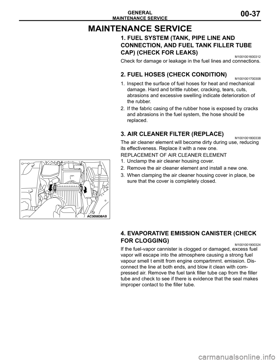
REPLACEMENT OF AIR CLEANER ELEMENT
1. Unclamp the air cleaner housing cover.
2. Remove the air cleaner element and install a new one.
3. When clamping the air cleaner housing cover in place, be
sure that the cover is completely closed.
4. EVAPORATIVE EMISSION CANISTER (CHECK
FOR CLOGGING)
M1001001900324
If the fuel-vapor cannister is clogged or damaged, excess fuel
vapor will escape into the atmosphere causing a strong fuel
vapour smell t emitt from engine compartmrnt. emission. Dis-
connect the line at both ends, and blow it clean with com-
pressed air. Remove the fuel tank filler tube cap from the filler
tube and check to see if there is evidence that the seal makes
improper contact to the filler tube.