2005 MITSUBISHI 380 transmission fluid
[x] Cancel search: transmission fluidPage 555 of 1500
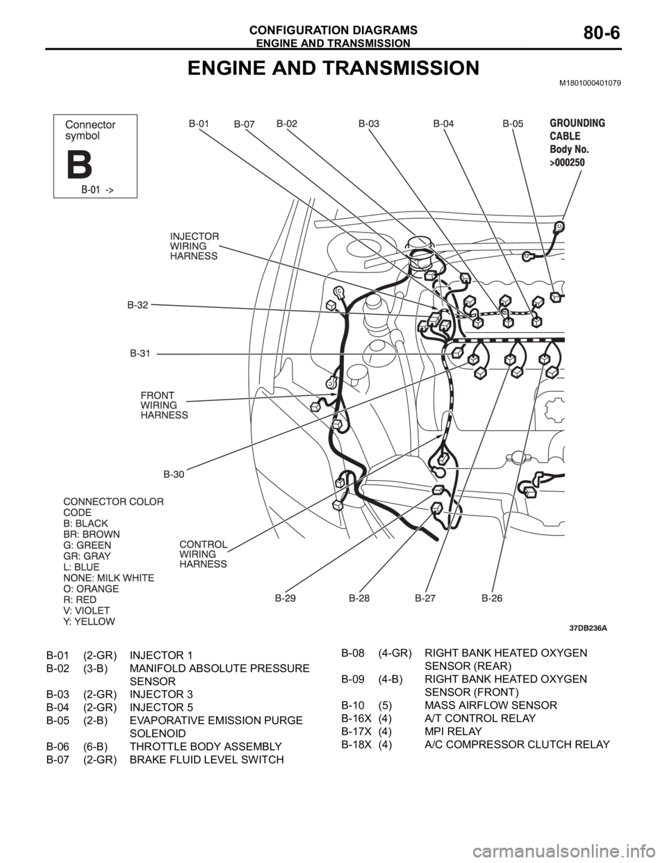
ENGINE AND TRANSMISSION
CONFIGURATION DIAGRAMS80-6
ENGINE AND TRANSMISSIONM1801000401079
B-01 (2-GR) INJECTOR 1
B-02 (3-B) MANIFOLD ABSOLUTE PRESSURE
SENSOR
B-03 (2-GR) INJECTOR 3
B-04 (2-GR) INJECTOR 5
B-05 (2-B) EVAPORATIVE EMISSION PURGE
SOLENOID
B-06 (6-B) THROTTLE BODY ASSEMBLY
B-07 (2-GR) BRAKE FLUID LEVEL SWITCHB-08 (4-GR) RIGHT BANK HEATED OXYGEN
SENSOR (REAR)
B-09 (4-B) RIGHT BANK HEATED OXYGEN
SENSOR (FRONT)
B-10 (5) MASS AIRFLOW SENSOR
B-16X (4) A/T CONTROL RELAY
B-17X (4) MPI RELAY
B-18X (4) A/C COMPRESSOR CLUTCH RELAY
Page 887 of 1500

INSPECTION TERMINAL
COMPONENT LOCATIONS70-8
INSPECTION TERMINALM1701000200354
SENSORM1701000600415
NAME SYMBOL NAME SYMBOL
A/C pressure sensor I Interior temperature sensor
A/T control solenoid valve assembly
(Incorporating transmission fluid
temperature sensor)N Knock sensor C
Accelerator pedal position sensor R Left bank heated oxygen sensor (front)
<3.8L Engine>P
Air thermo sensor T Left bank heated oxygen sensor (rear)
<3.8L Engine>P
Ambient temperature sensor L Manifold absolute pressure sensor B
Camshaft position sensor D Mass airflow sensor G
Crankshaft position sensor A Sunroof assembly (Incorporating pulse
sensor)U
Fuel pump module (Incorporating fuel
level sensor (main) and fuel tank
temperature sensor)W Output shaft speed sensor H
Fuel level sensor (sub) V Photo sensor
Right bank heated oxygen sensor
(front) <3.8L Engine>O
Input shaft speed sensor K Right bank heated oxygen sensor (rear)
<3.8L Engine>O
Page 1167 of 1500
GENERAL DESCRIPTION
BASIC BRAKE SYSTEM35A-2
GENERAL DESCRIPTIONM1351000100440
The brake system has been designed to give greater
reliability and durability and to provide excellent brak-
ing performance.
FEATURES
.
Improved braking performance
1. An 8+9 inch tandem brake booster provides suffi-
cient braking force in sudden braking range.
2. 296mm front ventilated disc brakes provide sta-
ble braking force and improved braking feel.
3. 303mm rear ventillated disc brakes are used.
.
Improved stability
1. A 4-wheel anti-lock braking system (4ABS) pre-
vents slipping caused by the vehicle wheels lock-
ing up, in order to maintain a stable vehicle
posture and steering performance.
2. An electronic brake-force distribution (EBD)
makes it possible to maintain the maximum
amount of braking force even when the vehicle's
load is unevenly distributed. 3. Front- and rear-wheel X-type brake line layout
are used.
4. Ventilated discs brakes improve anti-fading per-
formance.
.
Improved serviceability
1. A diagnosis function for the ABS system makes
inspection easier.
2. An outer disc separated hub and rotor make
removal and installation easier.
3. The master cylinder reservoir is utilised for both
brake and clutch fluid on manual transmission
vehicles.
4. The master cylinder filter is coloured black for
improved viewing.
5. The ABS-ECU and hydraulic unit are integrated
to make them more compact and light weight.
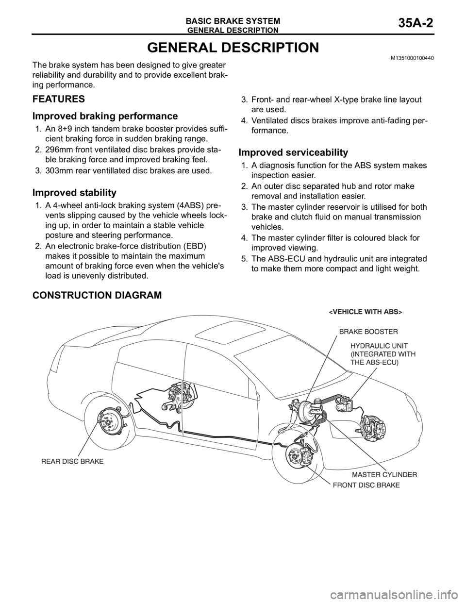
CONSTRUCTION DIAGRAM
Page 1223 of 1500
GENERAL00-2
MAINTENANCE SERVICE . . . . . . . .00-37
1. FUEL SYSTEM (TANK, PIPE LINE AND
CONNECTION, AND FUEL TANK FILLER
TUBE CAP) (CHECK FOR LEAKS) . . . . . . 00-37
2. FUEL HOSES (CHECK CONDITION) . . 00-37
3. AIR CLEANER FILTER (REPLACE). . . . 00-37
4. EVAPORATIVE EMISSION SYSTEM
(EXCEPT EVAPORATIVE EMISSION
CANISTER) (CHECK FOR CLOGGING) . . 00-37
5. SPARK PLUGS (REPLACE). . . . . . . . . . 00-38
7. TIMING BELT (REPLACE) . . . . . . . . . . . 00-38
8. DRIVE BELTS (FOR ALTERNATOR, POWER
STEERING PUMP AND AIR CONDITIONING)
(CHECK) . . . . . . . . . . . . . . . . . . . . . . . . . . . 00-39
9. EXHAUST SYSTEM (CONNECTIONS
PORTION OF MUFFLER, MUFFLER PIPES
AND CONVERTER HEAT SHIELDS) (CHECK
AND SERVICE AS REQUIRED) . . . . . . . . . 00-44
10. ENGINE OIL (CHANGE) . . . . . . . . . . . . 00-4411. ENGINE OIL FILTER (REPLACE) . . . . 00-44
12. TRANSMISSION FLUID . . . . . . . . . . . . 00-45
13. ENGINE COOLANT (CHANGE) . . . . . . 00-47
14. COOLANT HOSES (RADIATOR HOSE,
HEATER HOSE) (INSPECT). . . . . . . . . . . . 00-49
15. DISC BRAKE PADS, ROTORS
(INSPECT FOR WEAR) . . . . . . . . . . . . . . . 00-49
16. BRAKE HOSES (CHECK FOR
DETERIORATION OR LEAKS) . . . . . . . . . . 00-49
17. BALL JOINT AND STEERING LINKAGE
SEALS (INSPECT FOR GREASE LEAKS
AND DAMAGE) . . . . . . . . . . . . . . . . . . . . . . 00-50
18. DRIVE SHAFT BOOTS (INSPECT FOR
GREASE LEAKS AND DAMAGE) . . . . . . . . 00-50
19. SUSPENSION SYSTEM (INSPECT FOR
LOOSENESS AND DAMAGE) . . . . . . . . . . 00-51
20. SRS AIR BAG (INSPECT FOR SRS
SYSTEM). . . . . . . . . . . . . . . . . . . . . . . . . . . 00-51
21. TYRES (ROTATE). . . . . . . . . . . . . . . . . 00-58
Page 1248 of 1500
TOWING AND HOISTING
GENERAL00-27
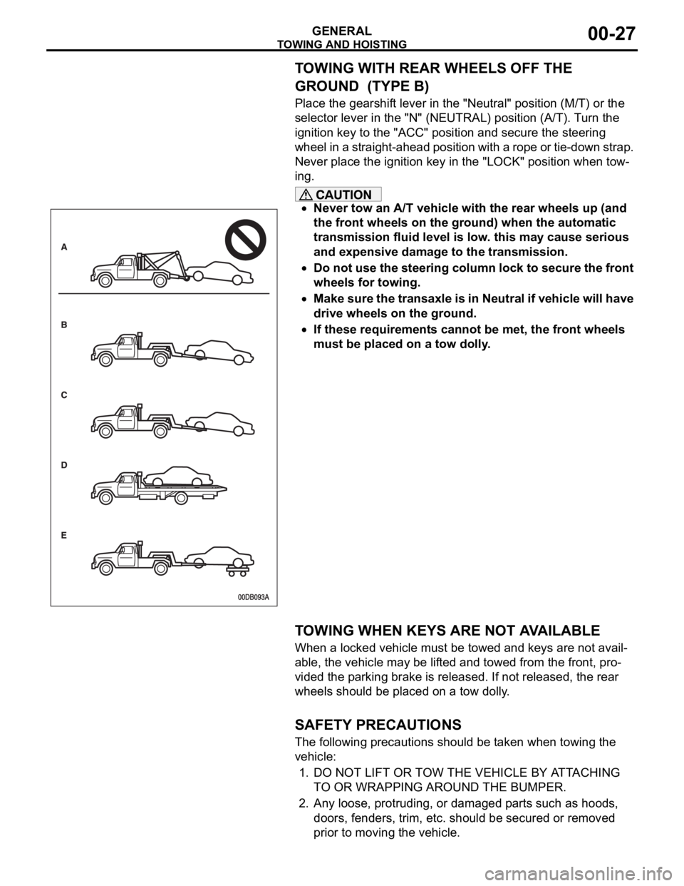
TOWING WITH REAR WHEELS OFF THE
GROUND (TYPE B)
Place the gearshift lever in the "Neutral" position (M/T) or the
selector lever in the "N" (NEUTRAL) position (A/T). Turn the
ignition key to the "ACC" position and secure the steering
wheel in a straight-ahead position with a rope or tie-down strap.
Never place the ignition key in the "LOCK" position when tow-
ing.
Never tow an A/T vehicle with the rear wheels up (and
the front wheels on the ground) when the automatic
transmission fluid level is low. this may cause serious
and expensive damage to the transmission.
Do not use the steering column lock to secure the front
wheels for towing.
Make sure the transaxle is in Neutral if vehicle will have
drive wheels on the ground.
If these requirements cannot be met, the front wheels
must be placed on a tow dolly.
.
TOWING WHEN KEYS ARE NOT AVAILABLE
When a locked vehicle must be towed and keys are not avail-
able, the vehicle may be lifted and towed from the front, pro-
vided the parking brake is released. If not released, the rear
wheels should be placed on a tow dolly.
.
SAFETY PRECAUTIONS
The following precautions should be taken when towing the
vehicle:
1. DO NOT LIFT OR TOW THE VEHICLE BY ATTACHING
TO OR WRAPPING AROUND THE BUMPER.
2. Any loose, protruding, or damaged parts such as hoods,
doors, fenders, trim, etc. should be secured or removed
prior to moving the vehicle.
Page 1256 of 1500

RECOMMENDED LUBRICANTS AND LUBRICANT CAPACITIES TABLE
GENERAL00-35
RECOMMENDED LUBRICANTS AND LUBRICANT
CAPACITIES TABLE
M1001001300504
RECOMMENDED LUBRICANTS
LUBRICANT CAPACITY TABLE
<3.8L ENGINE>LUBRICANT SPECIFICATION
Engine oil Engine oils conforming to ACEA A1, A2 or A3 and
AP1 SG or higher
AutomaticTransmission fluid Genuine Mitsubishi Motors ATF-SP III
Manual Transmission fluid Genuine Mitsubishi Motors MTF
Power steering fluid ATF DEXRON III or DEXRON II
Brakes fluid Conforming to DOT 3 or DOT 4
Engine coolant Genuine Mitsubishi Motors coolant
Refrigerant (air conditioning) HFC-134a
DESCRIPTION SPECIFICATION
Engine oil (Litres) Oil pan (excluding oil filter) 4.0
Oil filter 0.3
Engine coolant (Litres) 8.7
Automatic Transmission fluid (Litres) 8.4
Manual Transmission fluid (Litres) 2.8
Power steering fluid (Litres) 1.2
Fuel tank (Litres) 67.0
Washer fluid (Litres) 5.0
Refrigerant (air conditioning) (grams) 435g - 475g
Page 1266 of 1500
MAINTENANCE SERVICE
GENERAL00-45
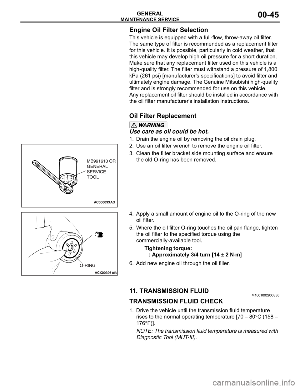
Engine Oil Filter Selection
This vehicle is equipped with a full-flow, throw-away oil filter.
The same type of filter is recommended as a replacement filter
for this vehicle. It is possible, particularly in cold weather, that
this vehicle may develop high oil pressure for a short duration.
Make sure that any replacement filter used on this vehicle is a
high-quality filter. The filter must withstand a pressure of 1,800
kPa (261 psi) [manufacturer's specifications] to avoid filter and
ultimately engine damage. The Genuine Mitsubishi high-quality
filter and is strongly recommended for use on this vehicle.
Any replacement oil filter should be installed in accordance with
the oil filter manufacturer's installation instructions.
.
Oil Filter Replacement
Use care as oil could be hot.
1. Drain the engine oil by removing the oil drain plug.
2. Use an oil filter wrench to remove the engine oil filter.
3. Clean the filter bracket side mounting surface and ensure
the old O-ring has been removed.
4. Apply a small amount of engine oil to the O-ring of the new
oil filter.
5. Where the oil filter O-ring touches the oil pan flange, tighten
the oil filter to the specified torque using the
commercially-available tool.
Tightening torque:
: Approximately 3/4 turn [14
2 Nm]
6. Add new engine oil through the oil filler.
11. TRANSMISSION FLUIDM1001002900338
TRANSMISSION FLUID CHECK
1. Drive the vehicle until the transmission fluid temperature
rises to the normal operating temperature [70
80C (158
176
F)].
NOTE: The transmission fluid temperature is measured with
Diagnostic Tool (MUT-III).
Page 1267 of 1500
![MITSUBISHI 380 2005 Workshop Manual MAINTENANCE SERVICE
GENERAL00-46
NOTE: If it takes some amount of time until the transmission
fluid reaches its normal operating temperature [70
80C
(158
176F)], check the transmission fluid lev MITSUBISHI 380 2005 Workshop Manual MAINTENANCE SERVICE
GENERAL00-46
NOTE: If it takes some amount of time until the transmission
fluid reaches its normal operating temperature [70
80C
(158
176F)], check the transmission fluid lev](/manual-img/19/57086/w960_57086-1266.png)
MAINTENANCE SERVICE
GENERAL00-46
NOTE: If it takes some amount of time until the transmission
fluid reaches its normal operating temperature [70
80C
(158
176F)], check the transmission fluid level by refer-
ring to the left diagram.
2. Park the vehicle on a level surface.
3. Move the selector lever through all positions to fill the torque
converter and the hydraulic circuits with fluid, and then move
the selector lever to the "N" position.
4. After wiping off any dirt around the dipstick, remove the
dipstick and check the condition of the transmission fluid.
NOTE: If the transmission fluid smells as if it is burnt, it
means that the transmission fluid has been contaminated by
fine particles from the bushings and friction materials. Tran-
saxle overhaul and cooler line flushing may be necessary.
5. Check transmission fluid level is at the "HOT" mark on the
dipstick. If the transmission fluid level is less than this, add
DIAMOND ATF SP III until the level reaches the "HOT"
mark.
NOTE: If the transmission fluid level is too low, the oil pump
will draw in air along with the transmission fluid, which will
cause to form bubbles. If the transmission fluid level is too
high, rotating components inside the transaxle will churn the
fluid and air into a foamy liquid. Both conditions (level too
low or too high) will cause the hydraulic pressure to drop,
which will result in late shifting and slipping of the clutches
and brakes.
NOTE: In either case, air bubbles can interfere with normal
valve, clutch, and brake operation. Also, foaming can cause
transmission fluid to escape from the transaxle vent where it
may be mistaken for a leak.