Page 1186 of 1500
ON-VEHICLE SERVICE
BASIC BRAKE SYSTEM35A-21
After a new brake disc is installed, always grind the
brake disc with an on-the-car type brake lathe. If this
step is not carried out, the brake disc run-out exceeds
the specified value, resulting in judder.
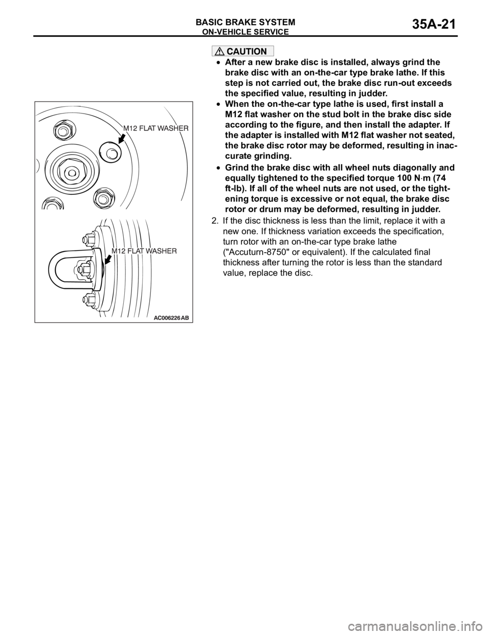
When the on-the-car type lathe is used, first install a
M12 flat washer on the stud bolt in the brake disc side
according to the figure, and then install the adapter. If
the adapter is installed with M12 flat washer not seated,
the brake disc rotor may be deformed, resulting in inac-
curate grinding.
Grind the brake disc with all wheel nuts diagonally and
equally tightened to the specified torque 100 N
m (74
ft-lb). If all of the wheel nuts are not used, or the tight-
ening torque is excessive or not equal, the brake disc
rotor or drum may be deformed, resulting in judder.
2. If the disc thickness is less than the limit, replace it with a
new one. If thickness variation exceeds the specification,
turn rotor with an on-the-car type brake lathe
("Accuturn-8750" or equivalent). If the calculated final
thickness after turning the rotor is less than the standard
value, replace the disc.
.
Page 1188 of 1500
ON-VEHICLE SERVICE
BASIC BRAKE SYSTEM35A-23
After a new brake disc is installed, always grind the
brake disc with an on-the-car type brake lathe. If this
step is not carried out, the brake disc run-out exceeds
the specified value, resulting in judder.
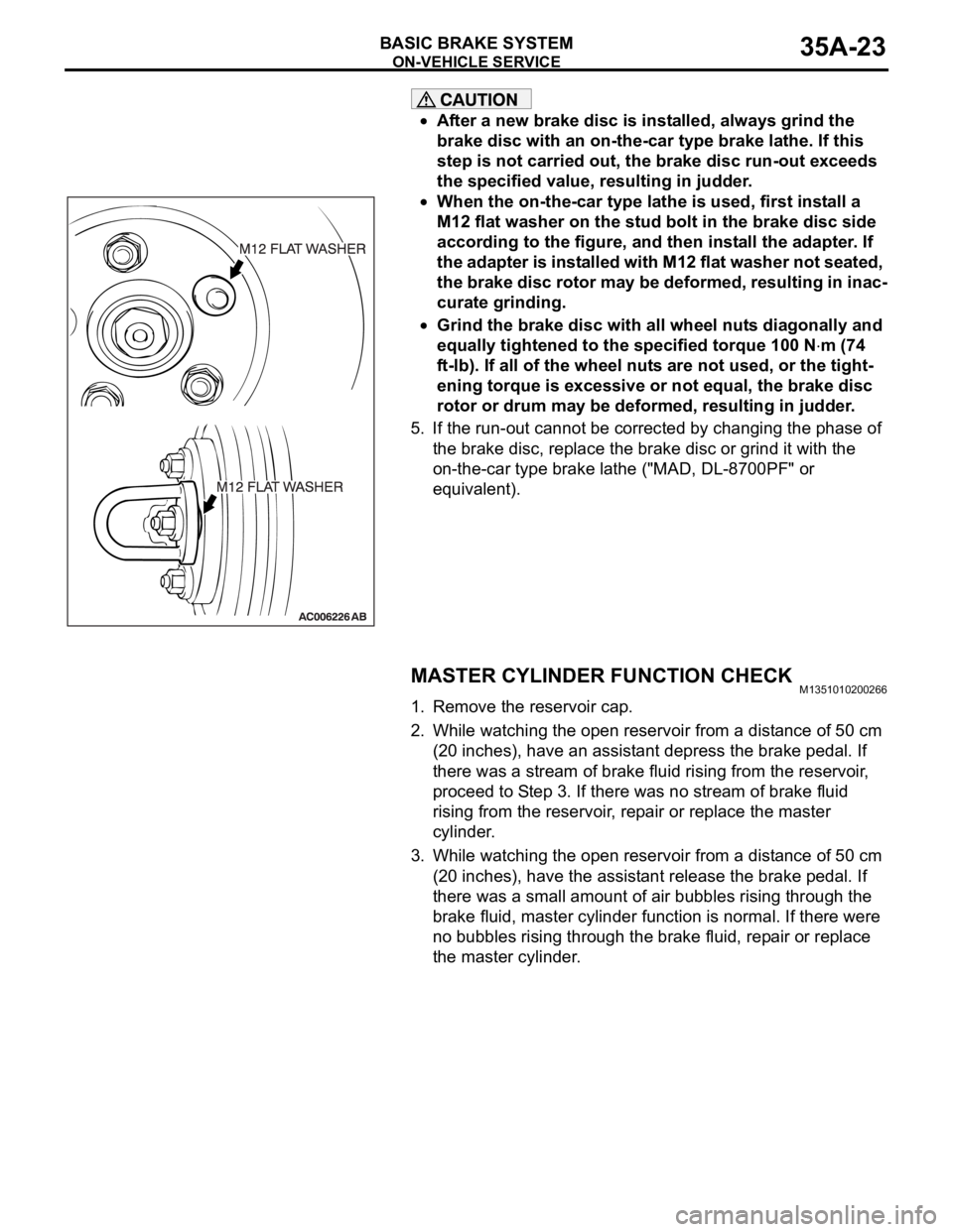
When the on-the-car type lathe is used, first install a
M12 flat washer on the stud bolt in the brake disc side
according to the figure, and then install the adapter. If
the adapter is installed with M12 flat washer not seated,
the brake disc rotor may be deformed, resulting in inac-
curate grinding.
Grind the brake disc with all wheel nuts diagonally and
equally tightened to the specified torque 100 N
m (74
ft-lb). If all of the wheel nuts are not used, or the tight-
ening torque is excessive or not equal, the brake disc
rotor or drum may be deformed, resulting in judder.
5. If the run-out cannot be corrected by changing the phase of
the brake disc, replace the brake disc or grind it with the
on-the-car type brake lathe ("MAD, DL-8700PF" or
equivalent).
MASTER CYLINDER FUNCTION CHECKM1351010200266
1. Remove the reservoir cap.
2. While watching the open reservoir from a distance of 50 cm
(20 inches), have an assistant depress the brake pedal. If
there was a stream of brake fluid rising from the reservoir,
proceed to Step 3. If there was no stream of brake fluid
rising from the reservoir, repair or replace the master
cylinder.
3. While watching the open reservoir from a distance of 50 cm
(20 inches), have the assistant release the brake pedal. If
there was a small amount of air bubbles rising through the
brake fluid, master cylinder function is normal. If there were
no bubbles rising through the brake fluid, repair or replace
the master cylinder.
Page 1425 of 1500
ON-VEHICLE SERVICE
FRONT AXLE26-8
ON-VEHICLE SERVICE
WHEEL BEARING END PLAY CHECKM1261000900246
1. Remove the caliper assembly and suspend it with a wire.
2. Remove the brake disc from the front hub.
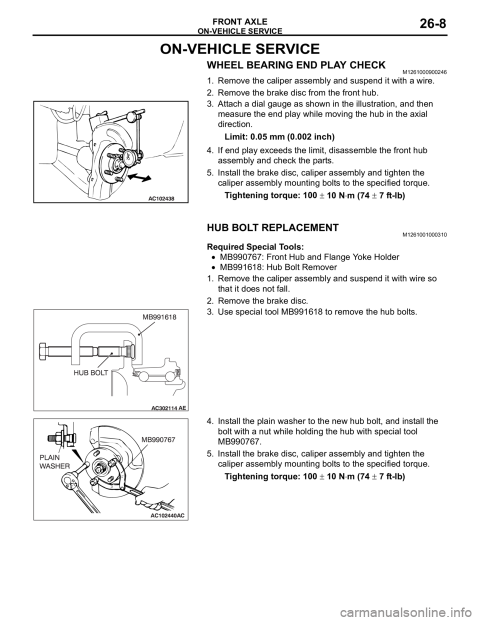
3. Attach a dial gauge as shown in the illustration, and then
measure the end play while moving the hub in the axial
direction.
Limit: 0.05 mm (0.002 inch)
4. If end play exceeds the limit, disassemble the front hub
assembly and check the parts.
5. Install the brake disc, caliper assembly and tighten the
caliper assembly mounting bolts to the specified torque.
Tightening torque: 100
10 Nm (74 7 ft-lb)
HUB BOLT REPLACEMENTM1261001000310
Required Special Tools:
MB990767: Front Hub and Flange Yoke Holder
MB991618: Hub Bolt Remover
1. Remove the caliper assembly and suspend it with wire so
that it does not fall.
2. Remove the brake disc.
3. Use special tool MB991618 to remove the hub bolts.
4. Install the plain washer to the new hub bolt, and install the
bolt with a nut while holding the hub with special tool
MB990767.
5. Install the brake disc, caliper assembly and tighten the
caliper assembly mounting bolts to the specified torque.
Tightening torque: 100
10 Nm (74 7 ft-lb)
Page 1446 of 1500
SPECIFICATIONS
FRONT AXLE26-29
SPECIFICATIONS
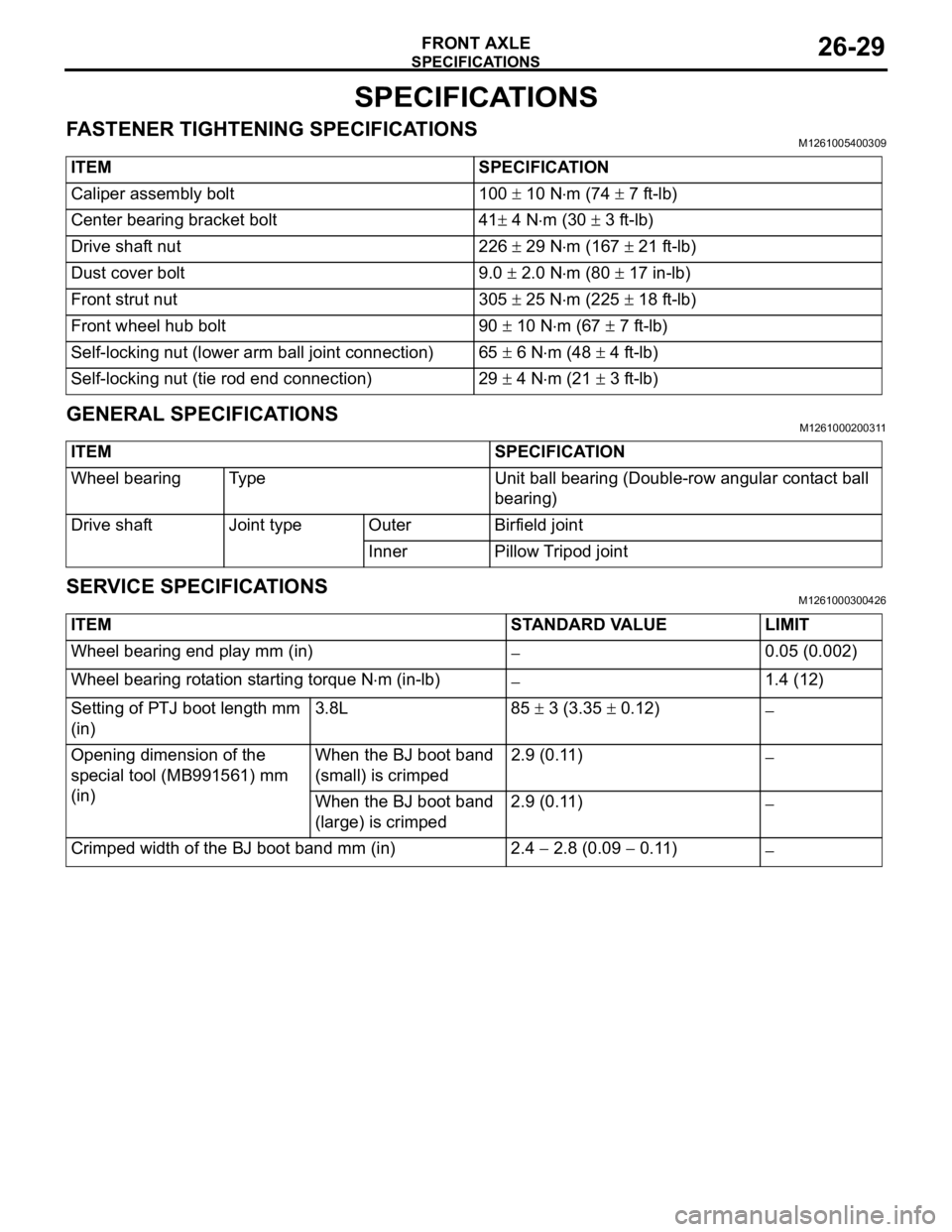
FASTENER TIGHTENING SPECIFICATIONSM1261005400309
GENERAL SPECIFICATIONSM1261000200311
SERVICE SPECIFICATIONSM1261000300426
ITEM SPECIFICATION
Caliper assembly bolt 100
10 Nm (74 7 ft-lb)
Center bearing bracket bolt 41
4 Nm (30 3 ft-lb)
Drive shaft nut 226
29 Nm (167 21 ft-lb)
Dust cover bolt 9.0
2.0 Nm (80 17 in-lb)
Front strut nut 305
25 Nm (225 18 ft-lb)
Front wheel hub bolt 90
10 Nm (67 7 ft-lb)
Self-locking nut (lower arm ball joint connection) 65
6 Nm (48 4 ft-lb)
Self-locking nut (tie rod end connection) 29
4 Nm (21 3 ft-lb)
ITEM SPECIFICATION
Wheel bearing Type Unit ball bearing (Double-row angular contact ball
bearing)
Drive shaft Joint type Outer Birfield joint
Inner Pillow Tripod joint
ITEM STANDARD VALUE LIMIT
Wheel bearing end play mm (in)
0.05 (0.002)
Wheel bearing rotation starting torque N
m (in-lb)1.4 (12)
Setting of PTJ boot length mm
(in)3.8L 85
3 (3.35 0.12)
Opening dimension of the
special tool (MB991561) mm
(in)When the BJ boot band
(small) is crimped2.9 (0.11)
When the BJ boot band
(large) is crimped2.9 (0.11)
Crimped width of the BJ boot band mm (in) 2.4 2.8 (0.09 0.11)
Page 1450 of 1500
REAR AXLE DIAGNOSIS
REAR AXLE27-3
SYMPTOM PROCEDURESM1271004400222
INSPECTION PROCEDURE 1: Abnormal Noise
DIAGNOSIS
STEP 1. Check the rear hub assembly installation bolts for
looseness.
Q: Are the rear hub assembly installation bolts loosened?
YES : Tighten the rear hub assembly installation bolts to the
specified torque 73
7 Nm (54 5 ft-lb). Then go to
St e p 4 .
NO : Go to Step 2.
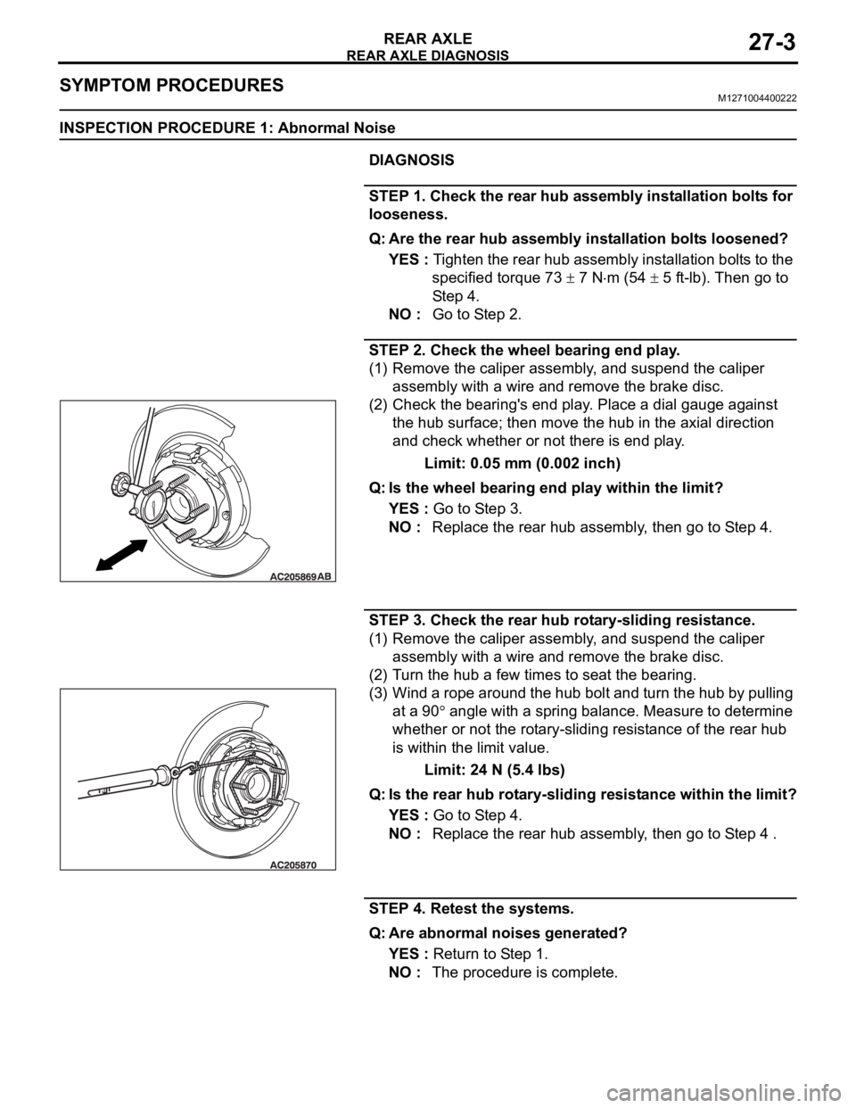
STEP 2. Check the wheel bearing end play.
(1) Remove the caliper assembly, and suspend the caliper
assembly with a wire and remove the brake disc.
(2) Check the bearing's end play. Place a dial gauge against
the hub surface; then move the hub in the axial direction
and check whether or not there is end play.
Limit: 0.05 mm (0.002 inch)
Q: Is the wheel bearing end play within the limit?
YES : Go to Step 3.
NO : Replace the rear hub assembly, then go to Step 4.
STEP 3. Check the rear hub rotary-sliding resistance.
(1) Remove the caliper assembly, and suspend the caliper
assembly with a wire and remove the brake disc.
(2) Turn the hub a few times to seat the bearing.
(3) Wind a rope around the hub bolt and turn the hub by pulling
at a 90
angle with a spring balance. Measure to determine
whether or not the rotary-sliding resistance of the rear hub
is within the limit value.
Limit: 24 N (5.4 lbs)
Q: Is the rear hub rotary-sliding resistance within the limit?
YES : Go to Step 4.
NO : Replace the rear hub assembly, then go to Step 4 .
STEP 4. Retest the systems.
Q: Are abnormal noises generated?
YES : Return to Step 1.
NO : The procedure is complete.
Page 1451 of 1500
SPECIAL TOOLS
REAR AXLE27-4
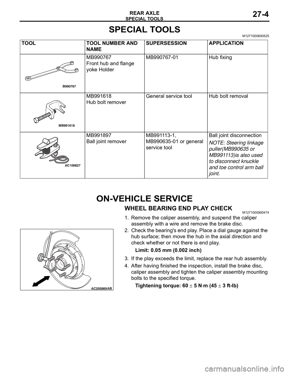
SPECIAL TOOLSM1271000600525
ON-VEHICLE SERVICE
WHEEL BEARING END PLAY CHECKM1271000900474
1. Remove the caliper assembly, and suspend the caliper
assembly with a wire and remove the brake disc.
2. Check the bearing's end play. Place a dial gauge against the
hub surface; then move the hub in the axial direction and
check whether or not there is end play.
Limit: 0.05 mm (0.002 inch)
3. If the play exceeds the limit, replace the rear hub assembly.
4. After having finished the inspection, install the brake disc,
caliper assembly and tighten the caliper assembly mounting
bolts to the specified torque.
Tightening torque: 60
5 Nm (45 3 ft-lb) TOOL TOOL NUMBER AND
NAMESUPERSESSION APPLICATION
MB990767
Front hub and flange
yoke HolderMB990767-01 Hub fixing
MB991618
Hub bolt removerGeneral service tool Hub bolt removal
MB991897
Ball joint removerMB991113-1,
MB990635-01 or general
service toolBall joint disconnection
NOTE: Steering linkage
puller(MB990635 or
MB991113)is also used
to disconnect knuckle
and toe control arm ball
joint.