Page 1157 of 1500

GENERAL INFORMATION
CLUTCH21A-2
GENERAL INFORMATION
M1211000100234
The clutch is a dry single-disc, diaphragm type;
hydraulic pressure is used for the clutch control. The
clutch shares a brake fluid reservoir with the brake
system.
SERVICE SPECIFICATIONS
M1211000300227
LUBRICANTS
M1211000400183
ON-VEHICLE SERVICE
CLUTCH PEDAL CHECK AND
ADJUSTMENT
M1211000900285
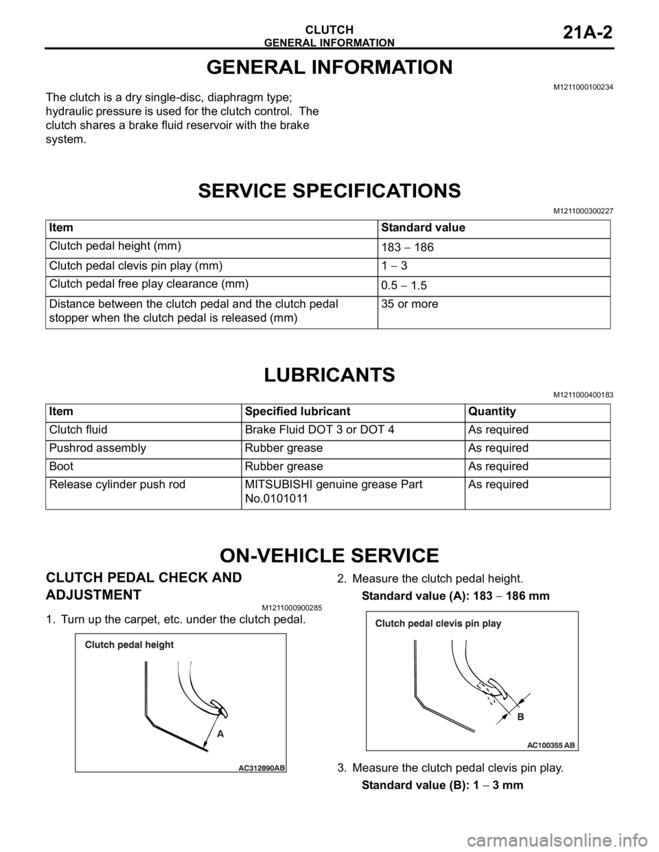
1. Turn up the carpet, etc. under the clutch pedal.2. Measure the clutch pedal height.
Standard value (A): 183
186 mm
3. Measure the clutch pedal clevis pin play.
Standard value (B): 1
3 mm Item Standard value
Clutch pedal height (mm)
183
186
Clutch pedal clevis pin play (mm) 1
3
Clutch pedal free play clearance (mm)
0.5
1.5
Distance between the clutch pedal and the clutch pedal
stopper when the clutch pedal is released (mm)35 or more
Item Specified lubricant Quantity
Clutch fluid Brake Fluid DOT 3 or DOT 4 As required
Pushrod assembly Rubber grease As required
Boot Rubber grease As required
Release cylinder push rod MITSUBISHI genuine grease Part
No.0101011As required
Page 1162 of 1500
CLUTCH CONTROL
CLUTCH21A-7
DISASSEMBLY AND REASSEMBLY
M1211002100230
CLUTCH MASTER CYLINDER
Do not disassemble the piston assembly.
Disassembly steps
1. Piston stopper ring
2. Piston assembly
>>A<<3. Pushrod assembly
4. Boot5. Spring pin
6. Nipple
7. Seal
8. Master cylinder bodyDisassembly steps (Continued)
Page 1196 of 1500

DISC BRAKE ASSEMBLY
BASIC BRAKE SYSTEM35A-31
INSTALLATION SERVICE POINT
.
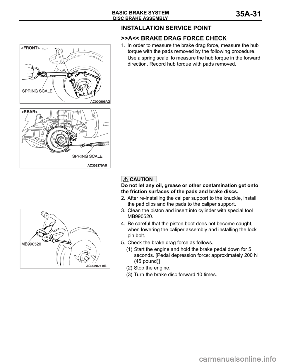
>>A<< BRAKE DRAG FORCE CHECK
1. In order to measure the brake drag force, measure the hub
torque with the pads removed by the following procedure.
Use a spring scale to measure the hub torque in the forward
direction. Record hub torque with pads removed.
Do not let any oil, grease or other contamination get onto
the friction surfaces of the pads and brake discs.
2. After re-installing the caliper support to the knuckle, install
the pad clips and the pads to the caliper support.
3. Clean the piston and insert into cylinder with special tool
MB990520.
4. Be careful that the piston boot does not become caught,
when lowering the caliper assembly and installing the lock
pin bolt.
5. Check the brake drag force as follows.
(1) Start the engine and hold the brake pedal down for 5
seconds. [Pedal depression force: approximately 200 N
(45 pound)]
(2) Stop the engine.
(3) Turn the brake disc forward 10 times.
Page 1198 of 1500
Page 1200 of 1500
Page 1201 of 1500
Page 1203 of 1500
Page 1206 of 1500
SPECIFICATIONS
BASIC BRAKE SYSTEM35A-41
SERVICE SPECIFICATIONSM1351000300477
LUBRICANTSM1351000400429
Rear brakes Type Floating caliper, Aluminium housing, 1 piston, ventilated disc
Disc effective dia
thickness
mm 303 18
Wheel cylinder I.D. mm 40.5
Pad thickness mm 10.0
Clearance adjustment Automatic ITEM SPECIFICATION
ITEM STANDARD VALUE LIMIT
Brake pedal height mm A/T 168.5
171.5
M/T 169.4 172.4
Brake pedal free play mm 3
8
Brake pedal to floor board clearance mm 110 or more
Disc brake pad thickness mm 10.0 Minimum 2.0
Disc brake disc thickness
mm Front 28.0 Minimum 26.4
Rear 18.0 Minimum 16.4
Disc brake disc run-out
mm Front
0.1
Rear
0.04
Disc brake drag force N Front 64 or less
Rear 54 or less
Hub end play mm 0.05
Brake booster push rod protruding length mm.
[When applying negative pressure of 66.7 kPa to the
brake booster]5.0
0.1
ITEM SPECIFIED LUBRICANT
Brake fluid DOT3 or DOT4
Piston boot, piston seal Repair kit grease
Front brake pin, rear brake pin (guide pin)