Page 1223 of 1500

GENERAL00-2
MAINTENANCE SERVICE . . . . . . . .00-37
1. FUEL SYSTEM (TANK, PIPE LINE AND
CONNECTION, AND FUEL TANK FILLER
TUBE CAP) (CHECK FOR LEAKS) . . . . . . 00-37
2. FUEL HOSES (CHECK CONDITION) . . 00-37
3. AIR CLEANER FILTER (REPLACE). . . . 00-37
4. EVAPORATIVE EMISSION SYSTEM
(EXCEPT EVAPORATIVE EMISSION
CANISTER) (CHECK FOR CLOGGING) . . 00-37
5. SPARK PLUGS (REPLACE). . . . . . . . . . 00-38
7. TIMING BELT (REPLACE) . . . . . . . . . . . 00-38
8. DRIVE BELTS (FOR ALTERNATOR, POWER
STEERING PUMP AND AIR CONDITIONING)
(CHECK) . . . . . . . . . . . . . . . . . . . . . . . . . . . 00-39
9. EXHAUST SYSTEM (CONNECTIONS
PORTION OF MUFFLER, MUFFLER PIPES
AND CONVERTER HEAT SHIELDS) (CHECK
AND SERVICE AS REQUIRED) . . . . . . . . . 00-44
10. ENGINE OIL (CHANGE) . . . . . . . . . . . . 00-4411. ENGINE OIL FILTER (REPLACE) . . . . 00-44
12. TRANSMISSION FLUID . . . . . . . . . . . . 00-45
13. ENGINE COOLANT (CHANGE) . . . . . . 00-47
14. COOLANT HOSES (RADIATOR HOSE,
HEATER HOSE) (INSPECT). . . . . . . . . . . . 00-49
15. DISC BRAKE PADS, ROTORS
(INSPECT FOR WEAR) . . . . . . . . . . . . . . . 00-49
16. BRAKE HOSES (CHECK FOR
DETERIORATION OR LEAKS) . . . . . . . . . . 00-49
17. BALL JOINT AND STEERING LINKAGE
SEALS (INSPECT FOR GREASE LEAKS
AND DAMAGE) . . . . . . . . . . . . . . . . . . . . . . 00-50
18. DRIVE SHAFT BOOTS (INSPECT FOR
GREASE LEAKS AND DAMAGE) . . . . . . . . 00-50
19. SUSPENSION SYSTEM (INSPECT FOR
LOOSENESS AND DAMAGE) . . . . . . . . . . 00-51
20. SRS AIR BAG (INSPECT FOR SRS
SYSTEM). . . . . . . . . . . . . . . . . . . . . . . . . . . 00-51
21. TYRES (ROTATE). . . . . . . . . . . . . . . . . 00-58
Page 1271 of 1500
MAINTENANCE SERVICE
GENERAL00-50
16. BALL JOINT AND STEERING LINKAGE
SEALS (INSPECT FOR GREASE LEAKS AND
DAMAGE)
M1001003500322
1. These components, which are permanently lubricated at the
factory, do not require periodic lubrication. Damaged seals
and boots should be replaced to prevent leakage or grease
contamination.
2. Inspect the dust cover and boots for proper sealing, leakage
and damage, and replace them if defective.
17. DRIVE SHAFT BOOTS (INSPECT FOR
GREASE LEAKS AND DAMAGE)
M1001003600318
1. These components, which are permanently lubricated at the
factory, do not require periodic lubrication. Damaged seals
and boots should be replaced to prevent leakage or grease
contamination.
2. Inspect the dust cover and boots for proper sealing, leakage
and damage. Replace them if defective.
Page 1418 of 1500

26-1
GROUP 26
FRONT AXLE
CONTENTS
GENERAL DESCRIPTION. . . . . . . . .26-2
FRONT AXLE DIAGNOSIS . . . . . . . .26-2
TROUBLESHOOTING STRATEGY . . . . . . 26-2
SYMPTOM CHART. . . . . . . . . . . . . . . . . . . 26-3
SYMPTOM PROCEDURES . . . . . . . . . . . . 26-3
SPECIAL TOOLS . . . . . . . . . . . . . . . .26-4
ON-VEHICLE SERVICE . . . . . . . . . . .26-8
WHEEL BEARING END PLAY CHECK . . . 26-8
HUB BOLT REPLACEMENT . . . . . . . . . . . 26-8
FRONT AXLE HUB ASSEMBLY . . . .26-9
REMOVAL AND INSTALLATION . . . . . . . . 26-9
INSPECTION. . . . . . . . . . . . . . . . . . . . . . . . 26-12
DRIVE SHAFT ASSEMBLY . . . . . . . .26-13
REMOVAL AND INSTALLATION . . . . . . . . 26-13
DISASSEMBLY AND ASSEMBLY . . . . . . . 26-18
INSPECTION. . . . . . . . . . . . . . . . . . . . . . . . 26-25
BJ BOOT REPLACEMENT . . . . . . . . . . . . . 26-26
SPECIFICATIONS . . . . . . . . . . . . . . .26-29
FASTENER TIGHTENING SPECIFICATIONS26-29
GENERAL SPECIFICATIONS . . . . . . . . . . 26-29
SERVICE SPECIFICATIONS . . . . . . . . . . . 26-29
LUBRICANTS . . . . . . . . . . . . . . . . . . . . . . . 26-30
Page 1423 of 1500
SPECIAL TOOLS
FRONT AXLE26-6
MB991172
Inner shaft
installer basePress-fitting of the inner shaft
MB991248
Inner shaft
removerMD998348-01 or
General service
tool Removal of the inner shaft
MB991561
Boot band
crimping toolMB991561 BJ boot (resin boot) band installation
MB990925
Bearing and oil
seal installer setMB990925-01 or
General service
tool
Removal and installation of the
center bearing
Press-fitting of the dust seal outer,
inner
MB990890
Rear suspension
bushing baseMB990890-01 Press-fitting of the dust seal outer, inner TOOL TOOL NUMBER
AND NAMESUPERSESSION APPLICATION
Page 1435 of 1500
Page 1436 of 1500
DRIVE SHAFT ASSEMBLY
FRONT AXLE26-19
BJ: Birfield Joint
For BJ boot removal and installation, refer to
P.26-26.
Required Special Tools:
MB991248: Inner Shaft Remover
MB990810: Side Bearing Puller
MB990930: Installer Adapter
MB990932: Installer Adapter
MB990934: Installer Adapter
MB990938: Bar (snap-in type)
MB990890: Rear Suspension Bushing Base
MB991172: Inner Shaft Installer Base
Page 1439 of 1500

DRIVE SHAFT ASSEMBLY
FRONT AXLE26-22
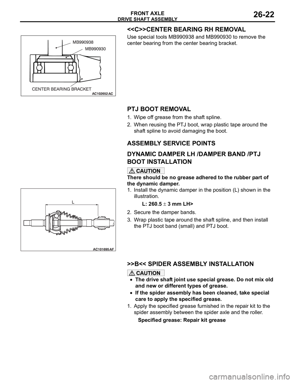
<>CENTER BEARING RH REMOVAL
Use special tools MB990938 and MB990930 to remove the
center bearing from the center bearing bracket.
.
PTJ BOOT REMOVAL
1. Wipe off grease from the shaft spline.
2. When reusing the PTJ boot, wrap plastic tape around the
shaft spline to avoid damaging the boot.
ASSEMBLY SERVICE POINTS
.
DYNAMIC DAMPER LH /DAMPER BAND /PTJ
BOOT INSTALLATION
There should be no grease adhered to the rubber part of
the dynamic damper.
1. Install the dynamic damper in the position (L) shown in the
illustration.
L: 260.5
3 mm LH>
2. Secure the damper bands.
3. Wrap plastic tape around the shaft spline, and then install
the PTJ boot band (small) and PTJ boot.
.
>>B<< SPIDER ASSEMBLY INSTALLATION
The drive shaft joint use special grease. Do not mix old
and new or different types of grease.
If the spider assembly has been cleaned, take special
care to apply the specified grease.
1. Apply the specified grease furnished in the repair kit to the
spider assembly between the spider axle and the roller.
Specified grease: Repair kit grease
Page 1442 of 1500

DRIVE SHAFT ASSEMBLY
FRONT AXLE26-25
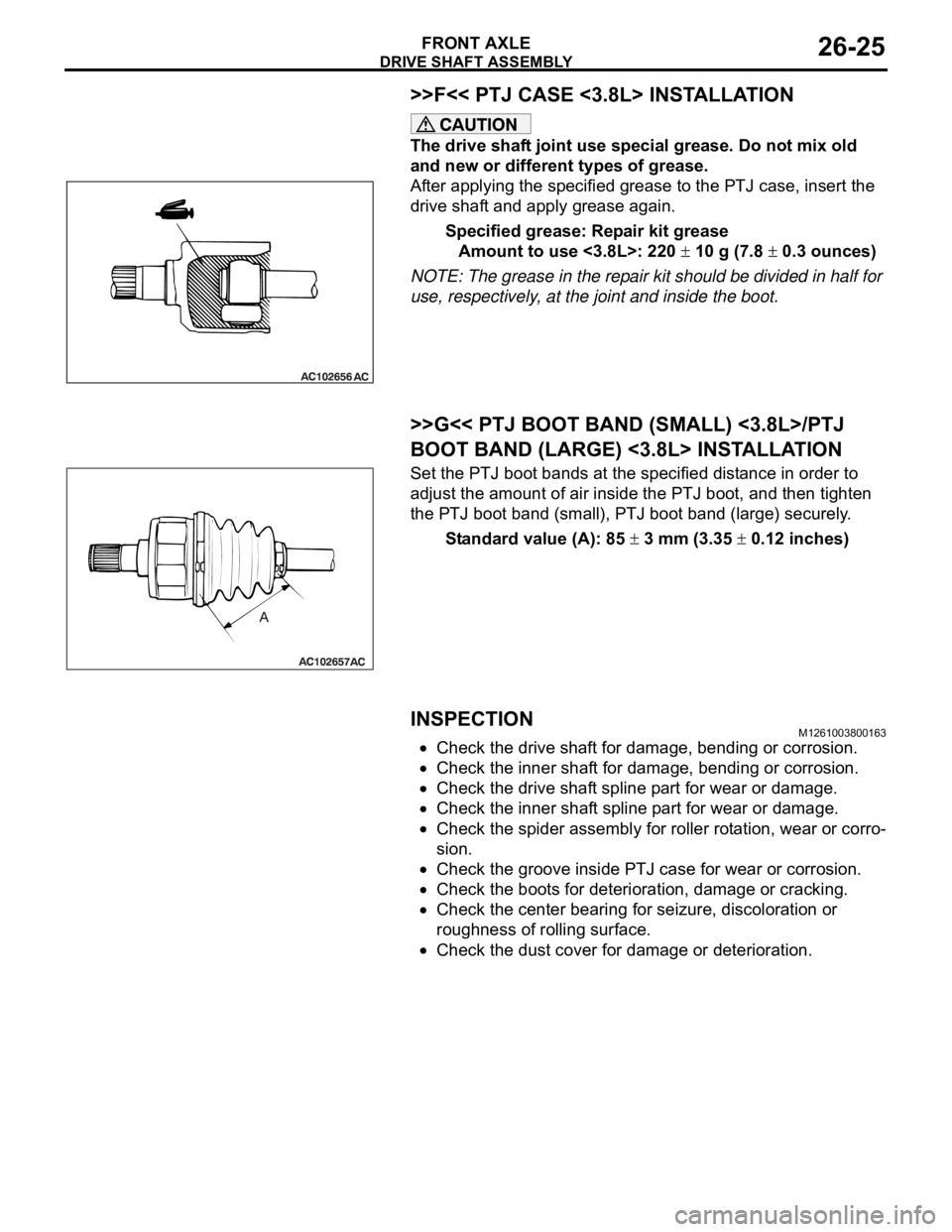
>>F<< PTJ CASE <3.8L> INSTALLATION
The drive shaft joint use special grease. Do not mix old
and new or different types of grease.
After applying the specified grease to the PTJ case, insert the
drive shaft and apply grease again.
Specified grease: Repair kit grease
Amount to use <3.8L>: 220
10 g (7.8 0.3 ounces)
NOTE: The grease in the repair kit should be divided in half for
use, respectively, at the joint and inside the boot.
.
>>G<< PTJ BOOT BAND (SMALL) <3.8L>/PTJ
BOOT BAND (LARGE) <3.8L> INSTALLATION
Set the PTJ boot bands at the specified distance in order to
adjust the amount of air inside the PTJ boot, and then tighten
the PTJ boot band (small), PTJ boot band (large) securely.
Standard value (A): 85
3 mm (3.35 0.12 inches)
INSPECTIONM1261003800163
Check the drive shaft for damage, bending or corrosion.
Check the inner shaft for damage, bending or corrosion.
Check the drive shaft spline part for wear or damage.
Check the inner shaft spline part for wear or damage.
Check the spider assembly for roller rotation, wear or corro-
sion.
Check the groove inside PTJ case for wear or corrosion.
Check the boots for deterioration, damage or cracking.
Check the center bearing for seizure, discoloration or
roughness of rolling surface.
Check the dust cover for damage or deterioration.