Page 508 of 1500
HEADLINING
INTERIOR52A-19
HEADLINING
REMOVAL AND INSTALLATIONM1521001400360
Pre-removal and Post-installation Operation
Front Seat Assembly (Refer to P.52A-21.)
Removal and Installation of Rear Seat Cushion Assembly
and Rear Seatback Assembly (Refer to P.52A-55.)
Removal and Installation of Front Pillar Trim, Center Pillar
Trim Upper and Rear Pillar Trim (Refer to P.52A-11.)
REMOVAL STEPS
1. SUN VISOR
2. SUN VISOR HOLDER
3. OVERHEAD CONSOLE
ASSEMBLY
4. DOME LIGHT ASSEMBLY (REFER
TO GROUP 54A, DOME LIGHT
P.54A-163.)
5. ASSIST GRIP PLUG
6. ROOF INSIDE ASSIST GRIP
ASSIST GRIP>
7. SUNROOF OPENING TRIM
8. ROOF HARNESS CLAMP
INSTRUMENT PANEL SIDE
COVER (REFER TO P.52A-4.)
9. ROOF HARNESS CONNECTOR
FLOOR CONSOLE ASSEMBLY
(REFER TO P.52A-10.)
PARKING BRAKE LEVER
ASSEMBLY MOUNTING BOLT
(REFER TO GROUP 36, PARKING
BRAKE LEVER P.36-6.)
<>10. HEADLINING ASSEMBLY
11. OVERHEAD CONSOLE BRACKET
12. FRONT HEADLINING PAD REMOVAL STEPS (Continued)
Page 555 of 1500
ENGINE AND TRANSMISSION
CONFIGURATION DIAGRAMS80-6
ENGINE AND TRANSMISSIONM1801000401079
B-01 (2-GR) INJECTOR 1
B-02 (3-B) MANIFOLD ABSOLUTE PRESSURE
SENSOR
B-03 (2-GR) INJECTOR 3
B-04 (2-GR) INJECTOR 5
B-05 (2-B) EVAPORATIVE EMISSION PURGE
SOLENOID
B-06 (6-B) THROTTLE BODY ASSEMBLY
B-07 (2-GR) BRAKE FLUID LEVEL SWITCHB-08 (4-GR) RIGHT BANK HEATED OXYGEN
SENSOR (REAR)
B-09 (4-B) RIGHT BANK HEATED OXYGEN
SENSOR (FRONT)
B-10 (5) MASS AIRFLOW SENSOR
B-16X (4) A/T CONTROL RELAY
B-17X (4) MPI RELAY
B-18X (4) A/C COMPRESSOR CLUTCH RELAY
Page 566 of 1500
FLOOR, SEAT AND ROOF
CONFIGURATION DIAGRAMS80-17
FLOOR, SEAT AND ROOFM1801000900930
D-01 (2) VANITY MIRROR LIGHT (RH)
D-02 (4) MAP LIGHT ASSEMBLY
SUNROOF>
D-03 (7) OVERHEAD CONSOLE ASSEMBLY
D-04 (10) SUNROOF ASSEMBLY
D-05 (2) VANITY MIRROR LIGHT (LH)
D-06 (3) REAR DOOR SWITCH (RH)
D-07 (3) REAR DOME LIGHT
D-09 (2) REAR SPEAKER (RH)
D-10 (2) TRUNK LAMP
D-11 (1) DEFOGGER (CHOKE COIL)
D-12 (2) REAR SPEAKER (LH)
D-13 (1-B) PARKING BRAKE SWITCHD-14 (6) A/T SHIFT SWITCH AND SELECT
POSITION ILLUMINATION LIGHT
D-15 (2) SUB WIRING HARNESS FOR
ACCESSORY SOCKET (2)
D-16 (3) REAR DOOR SWITCH (LH)
D-17 (2) FUEL LEVEL SENSOR (SUB)
D-18 (5-GR) FUEL PUMP MODULE
D-19 (10) FLOOR WIRING HARNESS AND
REAR DOOR WIRING HARNESS
(LH) COMBINATION
D-20 (2) SIDE IMPACT SENSOR (LH)
D-21 (2-B) SEAT BELT PRETENSIONER (LH)
D-22 (3) FRONT DOOR SWITCH (LH)
D-24 (2-R) SIDE AIR BAG MODULE (SQUIB)
(LH)
Page 578 of 1500

90-1
GROUP 90
CIRCUIT DIAGRAMS
CONTENTS
HOW TO READ CIRCUIT DIAGRAMS90-3
JUNCTION BLOCK . . . . . . . . . . . . . .90-9
JOINT CONNECTOR . . . . . . . . . . . . .90-11
CENTRALISED JUNCTION . . . . . . . .90-12
POWER DISTRIBUTION SYSTEM . .90-18
STARTING SYSTEM . . . . . . . . . . . . .90-21
IGNITION SYSTEM . . . . . . . . . . . . . .90-22
CHARGING SYSTEM . . . . . . . . . . . .90-23
MULTIPOINT FUEL INJECTION (MPI)
SYSTEM . . . . . . . . . . . . . . . . . . . . . . .90-24
COOLING SYSTEM . . . . . . . . . . . . . .90-29
INVECS-II 5A/T . . . . . . . . . . . . . . . . .90-30
HEADLAMPS . . . . . . . . . . . . . . . . . . .90-35
TAIL LAMP, POSITION LAMP, AND
LICENCE PLATE LAMP . . . . . . . . . .90-38
FOG LAMPS . . . . . . . . . . . . . . . . . . .90-41FRONT DOME LAMP, REAR DOME LAMP,
TRUNK LAMP AND IGNITION KEY HOLE
ILLUMINATION LAMP . . . . . . . . . . . .90-44
GLOVE BOX LAMP . . . . . . . . . . . . . .90-48
VANITY MIRROR LAMP. . . . . . . . . . .90-49
TURN-SIGNAL LAMP AND HAZARD
WARNING LAMP . . . . . . . . . . . . . . . .90-50
BACKUP LAMP . . . . . . . . . . . . . . . . .90-54
STOPLAMP. . . . . . . . . . . . . . . . . . . . .90-55
HORN . . . . . . . . . . . . . . . . . . . . . . . . .90-56
METER AND GAUGE . . . . . . . . . . . . .90-57
BRAKE WARNING LAMP, OIL
PRESSURE WARNING LAMP, FUEL
WARNING LAMP . . . . . . . . . . . . . . . .90-60
POWER WINDOWS . . . . . . . . . . . . . .90-62
CENTRAL DOOR LOCKING
SYSTEM . . . . . . . . . . . . . . . . . . . . . . .90-64
Continued on next page
Page 637 of 1500
BRAKE WARNING LAMP, OIL PRESSURE WARNING LAMP, FUEL WARNING LAMP
CIRCUIT DIAGRAMS90-60
BRAKE WARNING LAMP, OIL PRESSURE WARNING LAMP,
FUEL WARNING LAMP
M1901011800848
Page 638 of 1500
BRAKE WARNING LAMP, OIL PRESSURE WARNING LAMP, FUEL WARNING LAMP
CIRCUIT DIAGRAMS90-61
Page 1157 of 1500

GENERAL INFORMATION
CLUTCH21A-2
GENERAL INFORMATION
M1211000100234
The clutch is a dry single-disc, diaphragm type;
hydraulic pressure is used for the clutch control. The
clutch shares a brake fluid reservoir with the brake
system.
SERVICE SPECIFICATIONS
M1211000300227
LUBRICANTS
M1211000400183
ON-VEHICLE SERVICE
CLUTCH PEDAL CHECK AND
ADJUSTMENT
M1211000900285
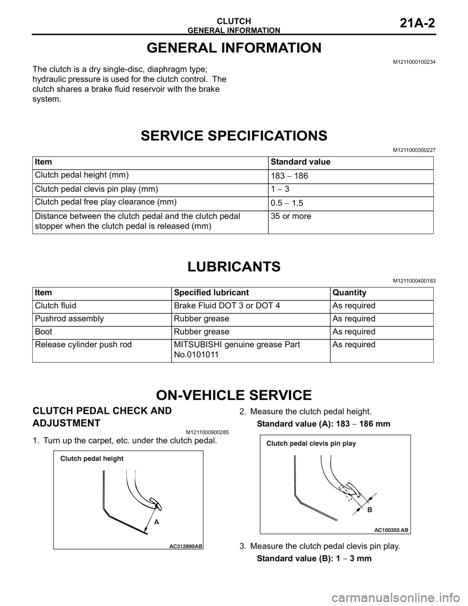
1. Turn up the carpet, etc. under the clutch pedal.2. Measure the clutch pedal height.
Standard value (A): 183
186 mm
3. Measure the clutch pedal clevis pin play.
Standard value (B): 1
3 mm Item Standard value
Clutch pedal height (mm)
183
186
Clutch pedal clevis pin play (mm) 1
3
Clutch pedal free play clearance (mm)
0.5
1.5
Distance between the clutch pedal and the clutch pedal
stopper when the clutch pedal is released (mm)35 or more
Item Specified lubricant Quantity
Clutch fluid Brake Fluid DOT 3 or DOT 4 As required
Pushrod assembly Rubber grease As required
Boot Rubber grease As required
Release cylinder push rod MITSUBISHI genuine grease Part
No.0101011As required
Page 1158 of 1500

ON-VEHICLE SERVICE
CLUTCH21A-3
Do not push in the master cylinder pushrod at
this time, otherwise the clutch will not operate
properly.
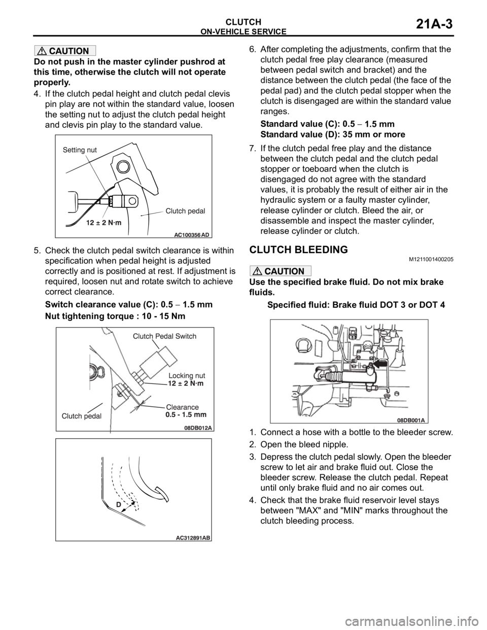
4. If the clutch pedal height and clutch pedal clevis
pin play are not within the standard value, loosen
the setting nut to adjust the clutch pedal height
and clevis pin play to the standard value.
5. Check the clutch pedal switch clearance is within
specification when pedal height is adjusted
correctly and is positioned at rest. If adjustment is
required, loosen nut and rotate switch to achieve
correct clearance.
Switch clearance value (C): 0.5
1.5 mm
Nut tightening torque : 10 - 15 Nm6. After completing the adjustments, confirm that the
clutch pedal free play clearance (measured
between pedal switch and bracket) and the
distance between the clutch pedal (the face of the
pedal pad) and the clutch pedal stopper when the
clutch is disengaged are within the standard value
ranges.
Standard value (C): 0.5
1.5 mm
Standard value (D): 35 mm or more
7. If the clutch pedal free play and the distance
between the clutch pedal and the clutch pedal
stopper or toeboard when the clutch is
disengaged do not agree with the standard
values, it is probably the result of either air in the
hydraulic system or a faulty master cylinder,
release cylinder or clutch. Bleed the air, or
disassemble and inspect the master cylinder,
release cylinder or clutch.
CLUTCH BLEEDINGM1211001400205
Use the specified brake fluid. Do not mix brake
fluids.
Specified fluid: Brake fluid DOT 3 or DOT 4
1. Connect a hose with a bottle to the bleeder screw.
2. Open the bleed nipple.
3. Depress the clutch pedal slowly. Open the bleeder
screw to let air and brake fluid out. Close the
bleeder screw. Release the clutch pedal. Repeat
until only brake fluid and no air comes out.
4. Check that the brake fluid reservoir level stays
between "MAX" and "MIN" marks throughout the
clutch bleeding process.