Page 1006 of 1500

STARTING SYSTEM
ENGINE ELECTRICAL16-29
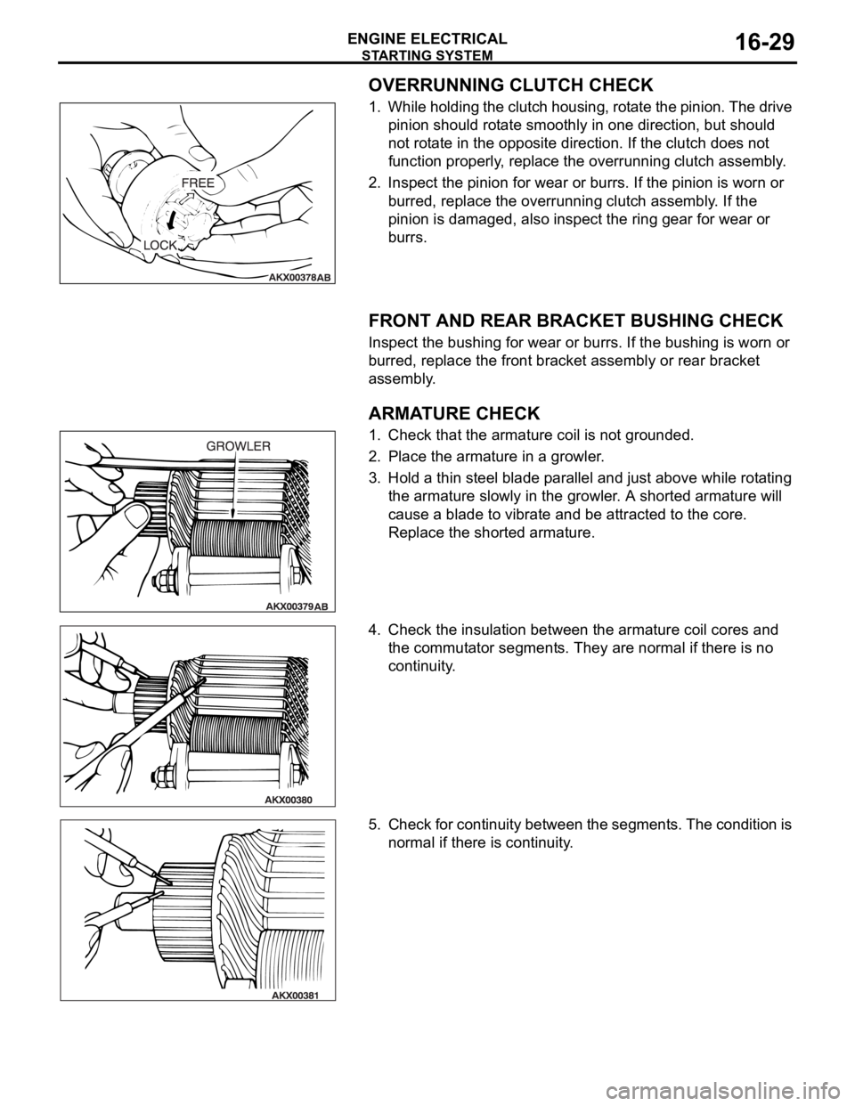
OVERRUNNING CLUTCH CHECK
1. While holding the clutch housing, rotate the pinion. The drive
pinion should rotate smoothly in one direction, but should
not rotate in the opposite direction. If the clutch does not
function properly, replace the overrunning clutch assembly.
2. Inspect the pinion for wear or burrs. If the pinion is worn or
burred, replace the overrunning clutch assembly. If the
pinion is damaged, also inspect the ring gear for wear or
burrs.
.
FRONT AND REAR BRACKET BUSHING CHECK
Inspect the bushing for wear or burrs. If the bushing is worn or
burred, replace the front bracket assembly or rear bracket
assembly.
.
ARMATURE CHECK
1. Check that the armature coil is not grounded.
2. Place the armature in a growler.
3. Hold a thin steel blade parallel and just above while rotating
the armature slowly in the growler. A shorted armature will
cause a blade to vibrate and be attracted to the core.
Replace the shorted armature.
4. Check the insulation between the armature coil cores and
the commutator segments. They are normal if there is no
continuity.
5. Check for continuity between the segments. The condition is
normal if there is continuity.
Page 1030 of 1500
CROSSMEMBER
POWER PLANT MOUNT32-13
<> FRONT AXLE CROSSMEMBER
MOUNTING BOLT REMOVAL
Remove the crossmember mounting bolt.
.
<> ENGINE REAR ROLL STOPPER BRACKET,
POWER STEERING GEAR AND LINKAGE,
STABILIZER BAR AND FRONT AXLE NO.1
CROSSMEMBER ASSEMBLY REMOVAL
Support the front axle number 1 crossmember with a transmis-
sion jack, and then remove the crossmember mounting nuts
and bolts.
INSTALLATION SERVICE POINTS
.
>>A<< STABILIZER BAR INSTALLATION
Align the stabilizer bar identification mark with the right end of
the bushing (LH).
.
Page 1161 of 1500
Page 1267 of 1500
![MITSUBISHI 380 2005 Workshop Manual MAINTENANCE SERVICE
GENERAL00-46
NOTE: If it takes some amount of time until the transmission
fluid reaches its normal operating temperature [70
80C
(158
176F)], check the transmission fluid lev MITSUBISHI 380 2005 Workshop Manual MAINTENANCE SERVICE
GENERAL00-46
NOTE: If it takes some amount of time until the transmission
fluid reaches its normal operating temperature [70
80C
(158
176F)], check the transmission fluid lev](/manual-img/19/57086/w960_57086-1266.png)
MAINTENANCE SERVICE
GENERAL00-46
NOTE: If it takes some amount of time until the transmission
fluid reaches its normal operating temperature [70
80C
(158
176F)], check the transmission fluid level by refer-
ring to the left diagram.
2. Park the vehicle on a level surface.
3. Move the selector lever through all positions to fill the torque
converter and the hydraulic circuits with fluid, and then move
the selector lever to the "N" position.
4. After wiping off any dirt around the dipstick, remove the
dipstick and check the condition of the transmission fluid.
NOTE: If the transmission fluid smells as if it is burnt, it
means that the transmission fluid has been contaminated by
fine particles from the bushings and friction materials. Tran-
saxle overhaul and cooler line flushing may be necessary.
5. Check transmission fluid level is at the "HOT" mark on the
dipstick. If the transmission fluid level is less than this, add
DIAMOND ATF SP III until the level reaches the "HOT"
mark.
NOTE: If the transmission fluid level is too low, the oil pump
will draw in air along with the transmission fluid, which will
cause to form bubbles. If the transmission fluid level is too
high, rotating components inside the transaxle will churn the
fluid and air into a foamy liquid. Both conditions (level too
low or too high) will cause the hydraulic pressure to drop,
which will result in late shifting and slipping of the clutches
and brakes.
NOTE: In either case, air bubbles can interfere with normal
valve, clutch, and brake operation. Also, foaming can cause
transmission fluid to escape from the transaxle vent where it
may be mistaken for a leak.
Page 1423 of 1500
SPECIAL TOOLS
FRONT AXLE26-6
MB991172
Inner shaft
installer basePress-fitting of the inner shaft
MB991248
Inner shaft
removerMD998348-01 or
General service
tool Removal of the inner shaft
MB991561
Boot band
crimping toolMB991561 BJ boot (resin boot) band installation
MB990925
Bearing and oil
seal installer setMB990925-01 or
General service
tool
Removal and installation of the
center bearing
Press-fitting of the dust seal outer,
inner
MB990890
Rear suspension
bushing baseMB990890-01 Press-fitting of the dust seal outer, inner TOOL TOOL NUMBER
AND NAMESUPERSESSION APPLICATION
Page 1436 of 1500
DRIVE SHAFT ASSEMBLY
FRONT AXLE26-19
BJ: Birfield Joint
For BJ boot removal and installation, refer to
P.26-26.
Required Special Tools:
MB991248: Inner Shaft Remover
MB990810: Side Bearing Puller
MB990930: Installer Adapter
MB990932: Installer Adapter
MB990934: Installer Adapter
MB990938: Bar (snap-in type)
MB990890: Rear Suspension Bushing Base
MB991172: Inner Shaft Installer Base