Page 1026 of 1500

CROSSMEMBER
POWER PLANT MOUNT32-9
CROSSMEMBER
REMOVAL AND INSTALLATIONM1321003200551
Before removing the steering wheel and air bag module assembly, always refer to GROUP 52B -
Service Precautions (P.52B-16), Air bag Module and Clock Spring (P.52B-237). Also, set the front
wheels so that they are facing straight forward, and remove the ignition key. If you fail to do this,
the SRS clock spring will be damaged, causing the SRS air bag to be inoperative and serious
injury.
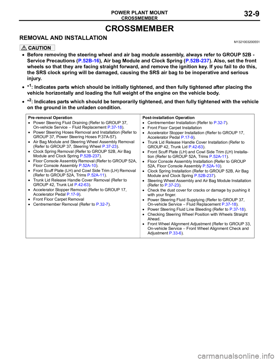
*1: Indicates parts which should be initially tightened, and then fully tightened after placing the
vehicle horizontally and loading the full weight of the engine on the vehicle body.
*2: Indicates parts which should be temporarily tightened, and then fully tightened with the vehicle
on the ground in the unladen condition.
Pre-removal Operation
Power Steering Fluid Draining (Refer to GROUP 37,
On-vehicle Service Fluid Replacement P.37-18).
Power Steering Hoses Removal and Installation (Refer to
GROUP 37, Power Steering Hoses P.37A-57).
Air Bag Module and Steering Wheel Assembly Removal
(Refer to GROUP 37, Steering Wheel P.37-23).
Clock Spring Removal (Refer to GROUP 52B, Air Bag
Module and Clock Spring P.52B-237).
Floor Console Assembly Removal (Refer to GROUP 52A,
Floor Console Assembly P.52A-10).
Front Scuff Plate (LH) and Cowl Side Trim (LH) Removal
(Refer to GROUP 52A, Trims P.52A-11).
Trunk Lid Release Handle Cover Removal (Refer to
GROUP 42, Trunk Lid P.42-63).
Accelerator Stopper Removal (Refer to GROUP 17,
Accelerator Pedal P.17-9).
Front Floor Carpet Removal
Centremember Removal (Refer to P.32-7).Post-installation Operation
Centremember Installation (Refer to P.32-7).
Front Floor Carpet Installation
Accelerator Stopper Installation (Refer to GROUP 17,
Accelerator Pedal P.17-9).
Trunk Lid Release Handle Cover Installation (Refer to
GROUP 42, Trunk Lid P.42-63).
Front Scuff Plate (LH) and Cowl Side Trim (LH) Installa-
tion (Refer to GROUP 52A, Trims P.52A-11).
Floor Console Assembly Installation (Refer to GROUP
52A, Floor Console Assembly P.52A-10).
Clock Spring Installation (Refer to GROUP 52B, Air Bag
Module and Clock Spring P.52B-237).
Steering Wheel Assembly and Air Bag Module Installation
(Refer to P.37-23).
Check the dust cover for cracks or damage by pushing it
with your finger.
Power Steering Fluid Supplying (Refer to GROUP 37,
On-vehicle Service Fluid Replacement P.37-18).
Power Steering Fluid Line Bleeding (Refer to P.37-18).
Checking Steering Wheel Position with Wheels Straight
Ahead.
Front Wheel Alignment Adjustment (Refer to GROUP 33,
On-vehicle Service
Front Wheel Alignment Check and
Adjustment P.33-6).
Page 1275 of 1500

MAINTENANCE SERVICE
GENERAL00-54
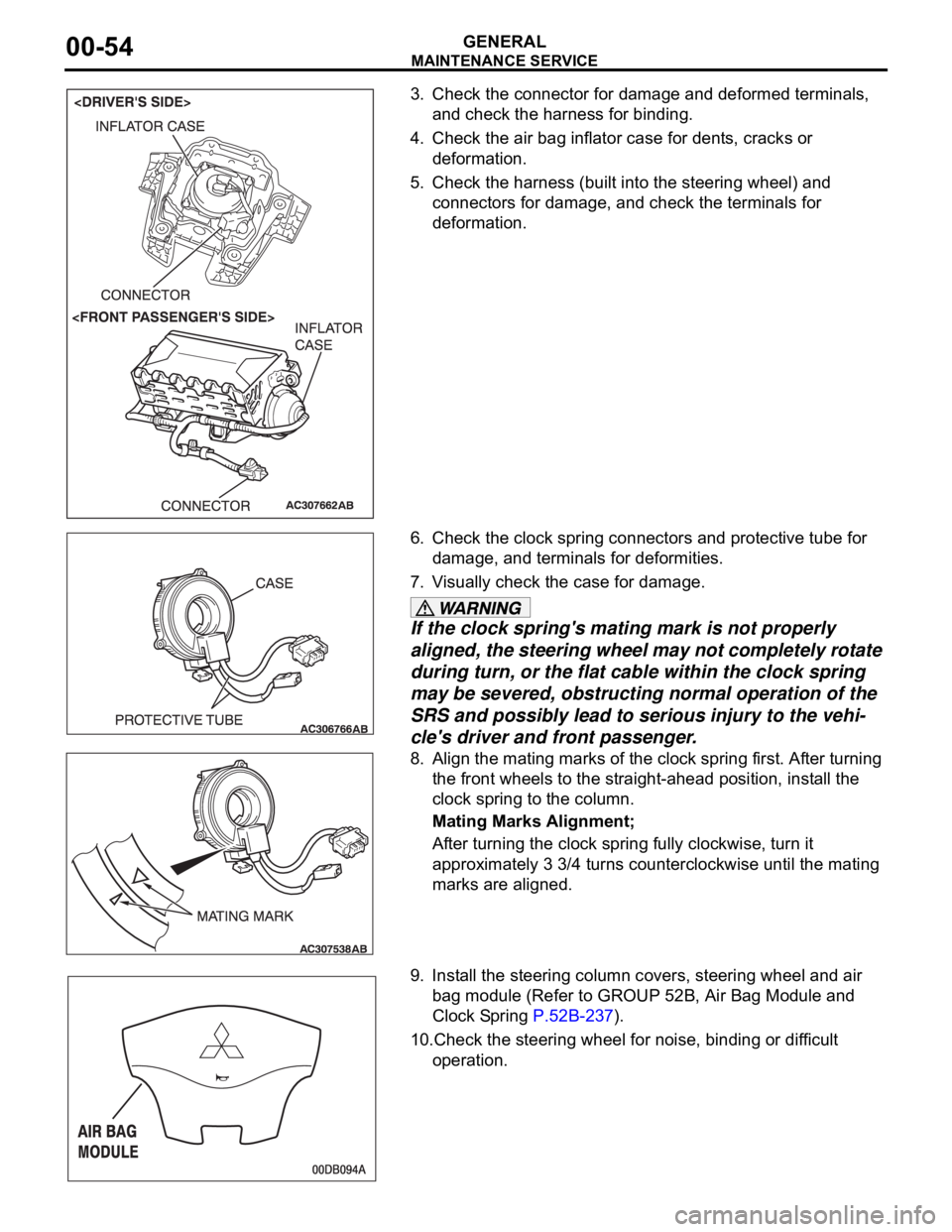
3. Check the connector for damage and deformed terminals,
and check the harness for binding.
4. Check the air bag inflator case for dents, cracks or
deformation.
5. Check the harness (built into the steering wheel) and
connectors for damage, and check the terminals for
deformation.
6. Check the clock spring connectors and protective tube for
damage, and terminals for deformities.
7. Visually check the case for damage.
If the clock spring's mating mark is not properly
aligned, the steering wheel may not completely rotate
during turn, or the flat cable within the clock spring
may be severed, obstructing normal operation of the
SRS and possibly lead to serious injury to the vehi-
cle's driver and front passenger.
8. Align the mating marks of the clock spring first. After turning
the front wheels to the straight-ahead position, install the
clock spring to the column.
Mating Marks Alignment;
After turning the clock spring fully clockwise, turn it
approximately 3 3/4 turns counterclockwise until the mating
marks are aligned.
9. Install the steering column covers, steering wheel and air
bag module (Refer to GROUP 52B, Air Bag Module and
Clock Spring P.52B-237).
10.Check the steering wheel for noise, binding or difficult
operation.
Page 1279 of 1500
MAINTENANCE SERVICE
GENERAL00-58
20. TYRES (ROTATE)M1001008900303
Rotate tyres regularly to equalize tyre wear and help extend
tyre life. Recommended tyre rotation is every 12,000 km under
normal driving conditions and every 9,600 km in severe driving
conditions.
Timing for the rotation may vary according to vehicle condition,
road surface conditions, and individual driver's habits.
When rotating tyres, check for uneven wear, damage, and
wheel alignment. Abnormal wear is usually caused by incorrect
tyre pressure, improper wheel alignment, out-of balance
wheels, or severe braking.
The first rotation is the most important, to achieve more uniform
wear for all tyres on the vehicle.