Page 556 of 1500
ENGINE AND TRANSMISSION
CONFIGURATION DIAGRAMS80-7
B-19 (34) A/T-ECU
B-20 (60) ENGINE-ECU
B-21 (94) ENGINE-ECU
B-22 (26) A/T-ECU
B-24 (4-GR) LEFT BANK HEATED OXYGEN
SENSOR (REAR)
B-25 (4-B) LEFT BANK HEATED OXYGEN
SENSOR (FRONT)
B-26 (2-GR) INJECTOR 6B-27 (2-GR) INJECTOR 4
B-28 (1-B) A/C COMPRESSOR ASSEMBLY
B-29 (1-B) ENGINE OIL PRESSURE SWITCH
B-30 (2-GR) INJECTOR 2
B-31 (1-B) POWER STEERING PRESSURE
SWITCH
B-32 (10-B) CONTROL WIRING HARNESS AND
INJECTOR WIRING HARNESS
COMBINATION
Page 578 of 1500

90-1
GROUP 90
CIRCUIT DIAGRAMS
CONTENTS
HOW TO READ CIRCUIT DIAGRAMS90-3
JUNCTION BLOCK . . . . . . . . . . . . . .90-9
JOINT CONNECTOR . . . . . . . . . . . . .90-11
CENTRALISED JUNCTION . . . . . . . .90-12
POWER DISTRIBUTION SYSTEM . .90-18
STARTING SYSTEM . . . . . . . . . . . . .90-21
IGNITION SYSTEM . . . . . . . . . . . . . .90-22
CHARGING SYSTEM . . . . . . . . . . . .90-23
MULTIPOINT FUEL INJECTION (MPI)
SYSTEM . . . . . . . . . . . . . . . . . . . . . . .90-24
COOLING SYSTEM . . . . . . . . . . . . . .90-29
INVECS-II 5A/T . . . . . . . . . . . . . . . . .90-30
HEADLAMPS . . . . . . . . . . . . . . . . . . .90-35
TAIL LAMP, POSITION LAMP, AND
LICENCE PLATE LAMP . . . . . . . . . .90-38
FOG LAMPS . . . . . . . . . . . . . . . . . . .90-41FRONT DOME LAMP, REAR DOME LAMP,
TRUNK LAMP AND IGNITION KEY HOLE
ILLUMINATION LAMP . . . . . . . . . . . .90-44
GLOVE BOX LAMP . . . . . . . . . . . . . .90-48
VANITY MIRROR LAMP. . . . . . . . . . .90-49
TURN-SIGNAL LAMP AND HAZARD
WARNING LAMP . . . . . . . . . . . . . . . .90-50
BACKUP LAMP . . . . . . . . . . . . . . . . .90-54
STOPLAMP. . . . . . . . . . . . . . . . . . . . .90-55
HORN . . . . . . . . . . . . . . . . . . . . . . . . .90-56
METER AND GAUGE . . . . . . . . . . . . .90-57
BRAKE WARNING LAMP, OIL
PRESSURE WARNING LAMP, FUEL
WARNING LAMP . . . . . . . . . . . . . . . .90-60
POWER WINDOWS . . . . . . . . . . . . . .90-62
CENTRAL DOOR LOCKING
SYSTEM . . . . . . . . . . . . . . . . . . . . . . .90-64
Continued on next page
Page 637 of 1500
BRAKE WARNING LAMP, OIL PRESSURE WARNING LAMP, FUEL WARNING LAMP
CIRCUIT DIAGRAMS90-60
BRAKE WARNING LAMP, OIL PRESSURE WARNING LAMP,
FUEL WARNING LAMP
M1901011800848
Page 638 of 1500
BRAKE WARNING LAMP, OIL PRESSURE WARNING LAMP, FUEL WARNING LAMP
CIRCUIT DIAGRAMS90-61
Page 704 of 1500

GENERAL DESCRIPTION
HEATER, AIR CONDITIONING AND VENTILATION55-3
GENERAL DESCRIPTIONM1552000100351
The heater and cooling units are combined in a sin-
gle unit, which, with the mode film damper and flow
rate control valve in the heater unit, reduces ventila-
tion resistance, increases fan power, and decreases
noise.
SAFETY PRECAUTIONS
Wear safety goggles and gloves when servic-
ing the refrigeration system to prevent
severe damage to eyes and hands.
Because R-134a refrigerant is a hydro fluorocarbon
(HFC) which contains hydrogen atoms in place of
chlorine atoms, it will not cause damage to the ozone
layer.
Ozone filters out harmful radiation from the sun. To
assist in protecting the ozone layer, Mitsubishi
Motors Corporation recommends an R-134a refriger-
ant recycling device.
Refrigerant R-134a is transparent and colorless in
both the liquid and vapor state. Since it has a boiling
point of
29.8C (21.64F) at atmospheric pressure,
it will be a vapor at all normal temperatures and pres-
sures. The vapor is heavier than air, non-flammable,
and non-explosive. The following precautions must
be observed when handling R-134a.
Do not heat R-134a above 40C (104.0F) or it
may catch fire and explode.
R-134a evaporates so rapidly at normal atmospheric
pressures and temperatures that it tends to freeze
anything it contacts. For this reason, extreme care
must be taken to prevent any liquid refrigerant from
contacting the skin and especially the eyes. Always
wear safety goggles when servicing the refrigeration
part of the A/C system. Keep a bottle of sterile min-
eral oil handy when working on the refrigeration sys-
tem.1. If any liquid refrigerant gets into your eyes, use a
few drops of mineral oil to wash them out. R-134a
is rapidly absorbed by the oil.
2. Next, splash your eyes with plenty of cold water.
3. Call your doctor immediately even if irritation has
ceased.
Keep R-134a containers upright when charging
the system.
In most instances, moderate heat is required to bring
the pressure of the refrigerant in its container above
the pressure of the system when charging or adding
refrigerant.
A bucket or large pan of hot water not over 40
C
(104.0
F) is all the heat required for this purpose. Do
not heat the refrigerant container with a blow torch or
any other means that would raise temperature and
pressure above this temperature. Do not weld or
steam-clean on or near the system components or
refrigerant lines.
A leak detector for R-134a should be used to
check for refrigerant gas leaks.
Do not allow liquid refrigerant to touch bright
metal or it will be stained.
When metering R-134a into the refrigeration system,
keep the supply tank or cans in an upright position. If
the refrigerant container is on its side or upside
down, liquid refrigerant will enter the system and
damage the compressor.
Refrigerant will tarnish bright metal and chrome sur-
faces, and in combination with moisture can severely
corrode all metal surfaces. ITEM SPECIFICATION
Heater control assembly Dial type
Compressor 10S17
Compressor Model Swashplate type
Refrigerant and quantity (g) R-134a (HFC-134a), 435
475
Page 843 of 1500

ON-VEHICLE SERVICE
HEATER, AIR CONDITIONING AND VENTILATION55-142
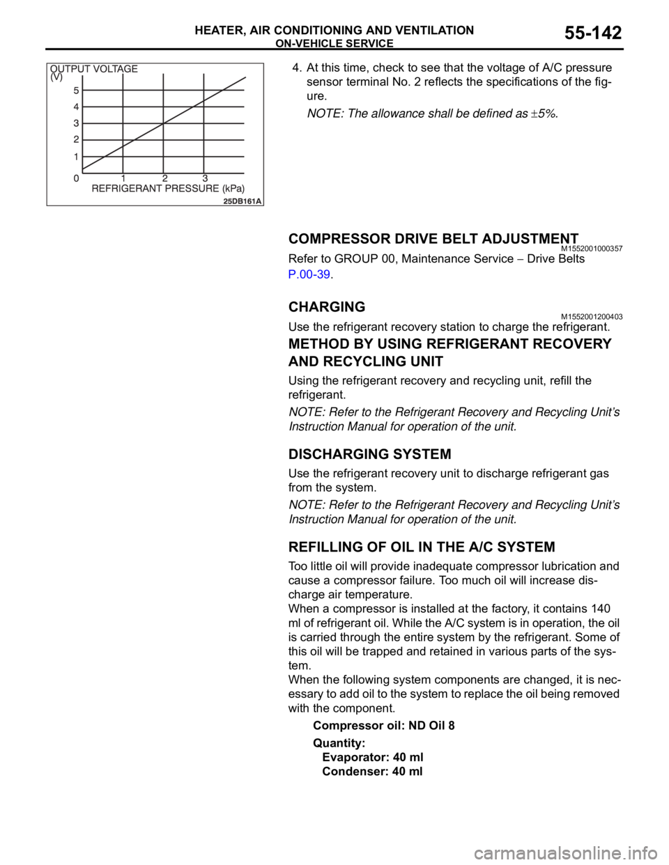
4. At this time, check to see that the voltage of A/C pressure
sensor terminal No. 2 reflects the specifications of the fig-
ure.
NOTE: The allowance shall be defined as
5%.
COMPRESSOR DRIVE BELT ADJUSTMENTM1552001000357
Refer to GROUP 00, Maintenance Service Drive Belts
P.00-39.
CHARGING M1552001200403
Use the refrigerant recovery station to charge the refrigerant.
METHOD BY USING REFRIGERANT RECOVERY
AND RECYCLING UNIT
Using the refrigerant recovery and recycling unit, refill the
refrigerant.
NOTE: Refer to the Refrigerant Recovery and Recycling Unit’s
Instruction Manual for operation of the unit.
DISCHARGING SYSTEM
Use the refrigerant recovery unit to discharge refrigerant gas
from the system.
NOTE: Refer to the Refrigerant Recovery and Recycling Unit’s
Instruction Manual for operation of the unit.
REFILLING OF OIL IN THE A/C SYSTEM
Too little oil will provide inadequate compressor lubrication and
cause a compressor failure. Too much oil will increase dis-
charge air temperature.
When a compressor is installed at the factory, it contains 140
ml of refrigerant oil. While the A/C system is in operation, the oil
is carried through the entire system by the refrigerant. Some of
this oil will be trapped and retained in various parts of the sys-
tem.
When the following system components are changed, it is nec-
essary to add oil to the system to replace the oil being removed
with the component.
Compressor oil: ND Oil 8
Quantity:
Evaporator: 40 ml
Condenser: 40 ml
Page 849 of 1500

ON-VEHICLE SERVICE
HEATER, AIR CONDITIONING AND VENTILATION55-148
POWER RELAY CHECKM1552008800321
BLOWER RELAY CONTINUITY CHECK
Hissing or swishing
noiseLow refrigerant quantity Refrigerant level Check system for leaks
and charge to
specification
Rattling (Internal
compressor)Lack of lubricating oil. In a
system with a gas leak
the oil has escaped with
the refrigerantRattling noise from
internal compressorRepalce the compressor
and also fix the system
leak to prevent
reoccurrance
Wooing (Resonant
noise)Drive accessory (P/S
pump, Alternator,etc)
resonating at specific
engine speedThe drive accessories for
vibrationStop vibrations of the
assembly or modify
transmission route to the
vehicle body
Cooing (Discharge
pulsation noise)Pressure fluctuation of
refrigerant discharged
from compressor, which
vibrates the high pressure
pipingRemove the piping
mounting clamps and
re-check. Hold the
condenser without
mountings by hand and
re-checkPut rubber bush between
pipe clamps and the
vehicle body. decrease
refrigerant to minimum
specified level. NOISE DESCRIPTION POSSIBLE CAUSE CHECK REPAIR
BATTERY
VOLTAGETESTER
CONNECTIONSPECIFIED
CONDITION
Not applied 4
5 Open circuit
Connect
terminal 1 to the
positive battery
terminal
Connect
terminal 3 to the
negative battery
terminal4
5 Less than 2 ohms
Page 919 of 1500

ENGINE COOLING DIAGNOSIS
ENGINE COOLING14-4
INSPECTION PROCEDURE 2: Engine Overheating
DIAGNOSIS
STEP 1. Remove the radiator cap and check for coolant
contamination.
Q: Is the coolant contaminated with rust and oil?
YES : Replace it. Refer to P.14-27.
NO : There is no action to be taken. Go to Step 2.
STEP 2. Check the radiator cap valve opening pressure.
NOTE: Be sure that the cap is clean before testing. Rust or
other foreign material on the cap seal will cause an improper
reading.
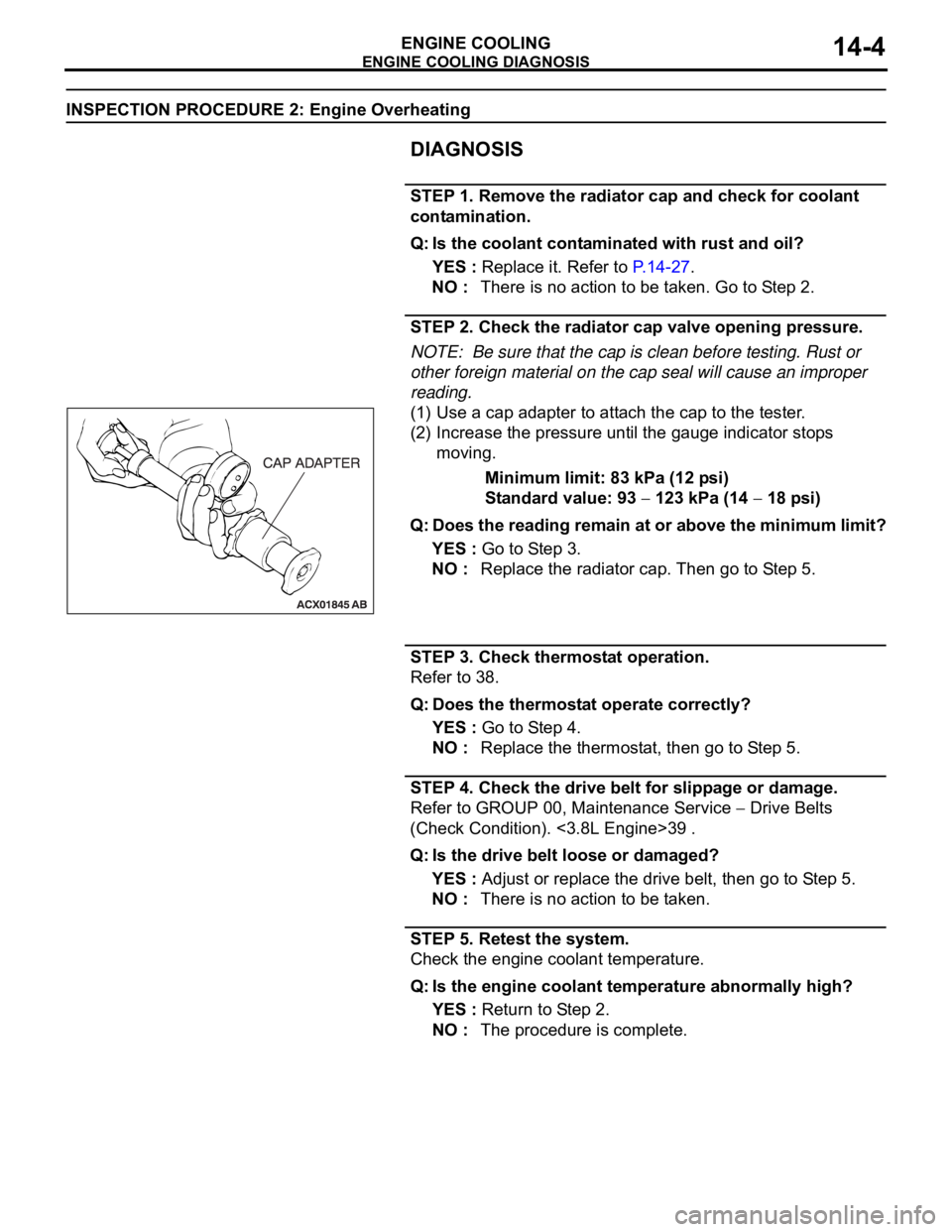
(1) Use a cap adapter to attach the cap to the tester.
(2) Increase the pressure until the gauge indicator stops
moving.
Minimum limit: 83 kPa (12 psi)
Standard value: 93
123 kPa (14 18 psi)
Q: Does the reading remain at or above the minimum limit?
YES : Go to Step 3.
NO : Replace the radiator cap. Then go to Step 5.
STEP 3. Check thermostat operation.
Refer to 38.
Q: Does the thermostat operate correctly?
YES : Go to Step 4.
NO : Replace the thermostat, then go to Step 5.
STEP 4. Check the drive belt for slippage or damage.
Refer to GROUP 00, Maintenance Service
Drive Belts
(Check Condition). <3.8L Engine>39 .
Q: Is the drive belt loose or damaged?
YES : Adjust or replace the drive belt, then go to Step 5.
NO : There is no action to be taken.
STEP 5. Retest the system.
Check the engine coolant temperature.
Q: Is the engine coolant temperature abnormally high?
YES : Return to Step 2.
NO : The procedure is complete.