2005 MITSUBISHI 380 diagnosis port
[x] Cancel search: diagnosis portPage 834 of 1500

AUTO A/C DIAGNOSIS
HEATER, AIR CONDITIONING AND VENTILATION55-133
DATA LIST REFERENCE TABLEM1554005100136
MUT-III
DIAGNOSTIC
TOOL DISPLAYITEM
NO.INSPECTION ITEM INSPECTION REQUIREMENT NORMAL VALUE
Inside
temperature
sensor59 Interior temperature
sensorIgnition switch: ON Inside air
temperature and
temperature
displayed on the
diagnostic tool are
identical.
Outside
temperature
sensor58 Outside temperature
sensorIgnition switch: ON Outside air
temperature and
temperature
displayed on the
diagnostic tool are
identical.
Air thermo sensor 20 Air thermo sensor Ignition switch: ON The temperature
measured behind
the evaporator
matches the
displayed value on
the diagnostic tool
while the engine is
cold.
Pressure sensor 61 A/C pressure sensor Ignition switch: ON Measured refrigerant
pressure is nearly
equal to the value
shown on the
diagnostic tool
(MPa).
Water
temperature
sensor62 Engine coolant
temperature sensor
(Data received by
CAN
Communication)Ignition switch: ON Engine coolant
temperature and
temperature
displayed on the
diagnostic tool are
identical.
Photo sensor 67 Photo sensor Ignition switch: ON Amount of light is
proportional to
voltage displayed on
the diagnostic tool.
Air mix
potentiometer63 Air mixing damper
control motor
potentiometerIgnition switch: ON Damper
positionOpening degree (V)
MAX. HOT Approx. 5
MAX. COOL Approx. 0
Air mix
potentiometer
(Target)64 Target value for air
mixing damper
control motor
potentiometerIgnition switch: ON Damper
positionOpening degree (V)
MAX. HOT Approx. 5
MAX. COOL Approx. 0
Page 1008 of 1500

IGNITION SYSTEM
ENGINE ELECTRICAL16-31
ON-VEHICLE SERVICE
KNOCK CONTROL SYSTEM CHECKM1163001800081
Check the knock sensor circuit if diagnostic trouble code, No.
P0325 is shown.
Refer to GROUP 13B, Multiport Fuel Injection (MPI)
Multiport
Fuel Injection (MPI) Diagnosis
Diagnostic Trouble Code Pro-
cedures
DTC P0325 : Knock Sensor Circuit 13A-346.
IGNITION COIL CHECK M1163001200380
Check by the following procedure, and replace the coil if there
is a malfunction.
.
PRIMARY COIL AND IGNITION POWER
TRANSISTOR CONTINUITY CHECK
NOTE: No test can be performed on the Primary side of coil.
.
SECONDARY COIL CHECK
NOTE: It is impossible to check the secondary coil through the
continuity check as a diode is integrated in the secondary coil
circuit of this ignition coil. Accordingly, check the secondary coil
in the following procedure.
1. Disconnect the ignition coil connector.
2. Remove the ignition coil and install a new spark plug to the
ignition coil.
3. Connect the ignition coil connector.
4. Disable vehicle fuel pump by removing fuel pump relay or
disconnecting fuel pump connector D-18 (under rear seat).
5. Ground the side electrode of the spark plug and crank the
engine.
6. Check that spark is produced between the electrodes of the
spark plug.
7. If no spark is produced, replace the ignition coil with a new
one and recheck.
8. If spark is produced with the new ignition coil, replace the
old one as it is faulty. If no spark is produced again, the
ignition circuit is suspected as faulty. Check the ignition
circuit.
Page 1009 of 1500

IGNITION SYSTEM
ENGINE ELECTRICAL16-32
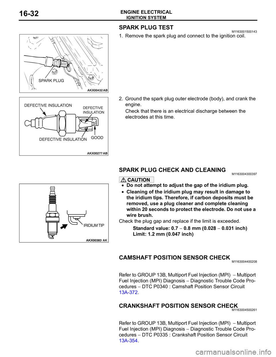
SPARK PLUG TESTM1163001500143
1. Remove the spark plug and connect to the ignition coil.
2. Ground the spark plug outer electrode (body), and crank the
engine.
Check that there is an electrical discharge between the
electrodes at this time.
SPARK PLUG CHECK AND CLEANING M1163004300397
Do not attempt to adjust the gap of the iridium plug.
Cleaning of the iridium plug may result in damage to
the iridium tips. Therefore, if carbon deposits must be
removed, use a plug cleaner and complete cleaning
within 20 seconds to protect the electrode. Do not use a
wire brush.
Check the plug gap and replace if the limit is exceeded.
Standard value: 0.7
0.8 mm (0.028 0.031 inch)
Limit: 1.2 mm (0.047 inch)
CAMSHAFT POSITION SENSOR CHECKM1163004400208
Refer to GROUP 13B, Multiport Fuel Injection (MPI) Multiport
Fuel Injection (MPI) Diagnosis
Diagnostic Trouble Code Pro-
cedures
DTC P0340 : Camshaft Position Sensor Circuit
13A-372.
CRANKSHAFT POSITION SENSOR CHECKM1163004500261
Refer to GROUP 13B, Multiport Fuel Injection (MPI) Multiport
Fuel Injection (MPI) Diagnosis
Diagnostic Trouble Code Pro-
cedures
DTC P0335 : Crankshaft Position Sensor Circuit
13A-354.
Page 1172 of 1500

BASIC BRAKE SYSTEM DIAGNOSIS
BASIC BRAKE SYSTEM35A-7
STEP 6. Check the master cylinder piston return spring for
damage and return port for clogging.
Refer to P.35A-28.
Q: Is there damage?
YES : Replace the part. Then go to Step 9.
NO : Go to Step 7.
STEP 7. Check port for clogging.
Q: Is the port clogged?
YES : Repair it. Then go to Step 9.
NO : Go to Step 8.
STEP 8. Check disc brake pistons for sticking.
Depress the brake pedal, then release. Confirm each wheel
spins freely.
Q: Does any wheel stick?
YES : Inspect that brake assembly. Then go to Step 9.
NO : Go to Step 9.
STEP 9. Recheck symptom.
Q: Is the symptom eliminated?
YES : The procedure is complete.
NO : Start over at step 1. If a new symptom surfaces, refer
to the symptom chart.
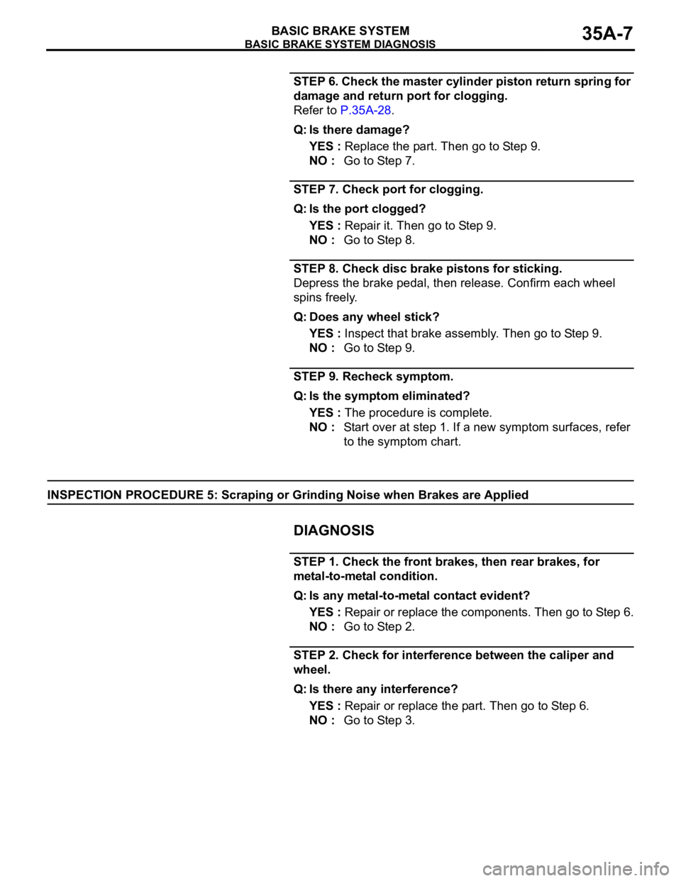
INSPECTION PROCEDURE 5: Scraping or Grinding Noise when Brakes are Applied
.
DIAGNOSIS
STEP 1. Check the front brakes, then rear brakes, for
metal-to-metal condition.
Q: Is any metal-to-metal contact evident?
YES : Repair or replace the components. Then go to Step 6.
NO : Go to Step 2.
STEP 2. Check for interference between the caliper and
wheel.
Q: Is there any interference?
YES : Repair or replace the part. Then go to Step 6.
NO : Go to Step 3.
Page 1227 of 1500

TROUBLESHOOTING GUIDELINES
GENERAL00-6
TROUBLESHOOTING GUIDELINESM1001008800340
VERIFY THE COMPLAINT
Make sure the customer's complaint and the ser-
vice writer's work order description are under-
stood before starting work.
Make sure you understand the correct operation
of the system. Read the service manual descrip-
tion to verify normal system operation.
Operate the system to see the symptoms. Look
for other symptoms that were not reported by the
customer, or on the work order, that may be
related to the problem.
DETERMINE POSSIBLE CAUSES
Compare the confirmed symptoms to the diagnostic
symptom indexes to find the right diagnosis proce-
dure.
If the confirmed symptoms cannot be found on any
symptom index, determine other possible causes.
Analyze the system diagrams and list all possible
causes for the problem symptoms.
Rank all these possible causes in order of proba-
bility, based on how much of the system they
cover, how likely they are to be the cause, and
how easy they will be to check. Be sure to take
experience into account. Consider the causes of
similar problems seen in the past. The list of
causes should be ranked in order from general to
specific, from most-likely to least-likely, and from
easy-to-check to hard-to-check.
FIND THE PROBLEM
After the symptoms have been confirmed, and prob-
able causes have been identified, the next step is to
make step-by-step checks of the suspected system
components, junctions, and links in logical order.
Use the diagnostic procedures in the service manual
whenever possible. Follow these procedures care-
fully to avoid missing an important step in the diagno-
sis sequence. It might be the skipped step that leads
to the solution of the problem.
If the service manual doesn't have step-by-step pro-
cedures to help diagnose the problem, make a series
of checks based on the ranked list of probable
causes. Troubleshooting checks should be made in
the order that the list of causes was ranked:
general to specific
most-likely to least-likely
easy-to-check to hard-to-check
REPAIR THE PROBLEM
When the step-by-step troubleshooting checks find a
fault, perform the proper repairs. Make sure to fix the
root cause of the problem, not just the symptom. Just
fixing the symptom, without fixing the root cause, will
cause the symptom to eventually return.
VERIFY THE REPAIR
After repairs are made, recheck the operation of the
system to confirm that the problem is eliminated. Be
sure to check the system thoroughly. Sometimes
new problems are revealed after repairs have been
made.
Page 1478 of 1500

AUTOMATIC TRANSMISSION DIAGNOSIS
AUTOMATIC TRANSMISSION23A-19
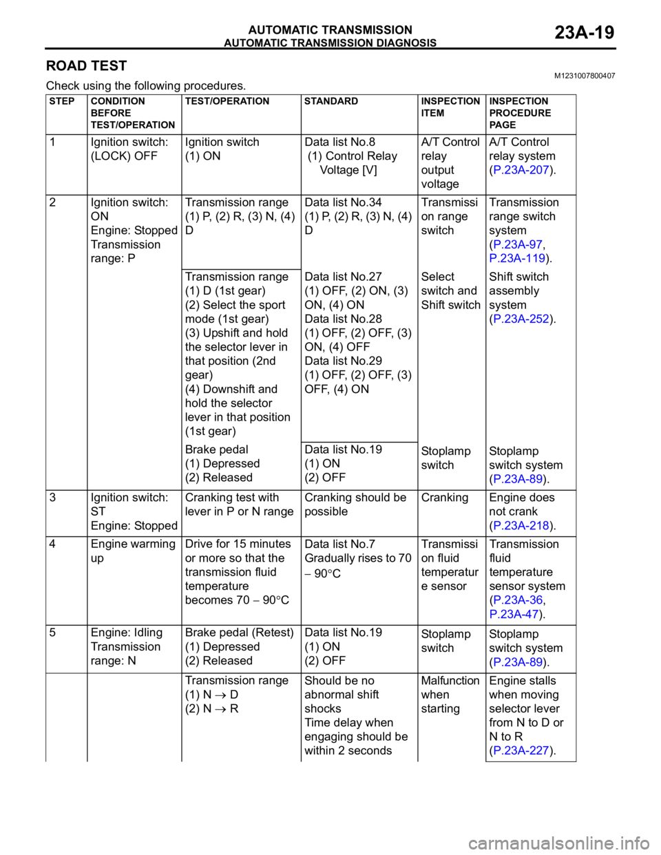
ROAD TESTM1231007800407
Check using the following procedures.
STEP CONDITION
BEFORE
TEST/OPERATIONTEST/OPERATION STANDARD INSPECTION
ITEMINSPECTION
PROCEDURE
PA G E
1 Ignition switch:
(LOCK) OFFIgnition switch
(1) ONData list No.8
(1) Control Relay
Voltage [V]A/T Control
relay
output
voltageA/T Control
relay system
(P.23A-207).
2 Ignition switch:
ON
Engine: Stopped
Transmission
range: PTransmission range
(1) P, (2) R, (3) N, (4)
DData list No.34
(1) P, (2) R, (3) N, (4)
DTransmissi
on range
switchTransmission
range switch
system
(P.23A-97,
P.23A-119).
Transmission range
(1) D (1st gear)
(2) Select the sport
mode (1st gear)
(3) Upshift and hold
the selector lever in
that position (2nd
gear)
(4) Downshift and
hold the selector
lever in that position
(1st gear)Data list No.27
(1) OFF, (2) ON, (3)
ON, (4) ON
Data list No.28
(1) OFF, (2) OFF, (3)
ON, (4) OFF
Data list No.29
(1) OFF, (2) OFF, (3)
OFF, (4) ONSelect
switch and
Shift switchShift switch
assembly
system
(P.23A-252).
Brake pedal
(1) Depressed
(2) ReleasedData list No.19
(1) ON
(2) OFFSto pl amp
switchSt o pla mp
switch system
(P.23A-89).
3 Ignition switch:
ST
Engine: StoppedCranking test with
lever in P or N rangeCranking should be
possibleCranking Engine does
not crank
(P.23A-218).
4 Engine warming
upDrive for 15 minutes
or more so that the
transmission fluid
temperature
becomes 70
90CData list No.7
Gradually rises to 70
90CTransmissi
on fluid
temperatur
e sensorTransmission
fluid
temperature
sensor system
(P.23A-36,
P.23A-47).
5 Engine: Idling
Transmission
range: NBrake pedal (Retest)
(1) Depressed
(2) ReleasedData list No.19
(1) ON
(2) OFFSto pl amp
switchSt o pla mp
switch system
(P.23A-89).
Transmission range
(1) N
D
(2) N
RShould be no
abnormal shift
shocks
Time delay when
engaging should be
within 2 secondsMalfunction
when
startingEngine stalls
when moving
selector lever
from N to D or
N to R
(P.23A-227).
Page 1486 of 1500
![MITSUBISHI 380 2005 Workshop Manual AUTOMATIC TRANSMISSION DIAGNOSIS
AUTOMATIC TRANSMISSION23A-27
3. Connect the special tools (3.0 MPa (427 psi) oil pressure
gauge [MD998330] and adapters [MD998332, MD998900])
to each pressure discha MITSUBISHI 380 2005 Workshop Manual AUTOMATIC TRANSMISSION DIAGNOSIS
AUTOMATIC TRANSMISSION23A-27
3. Connect the special tools (3.0 MPa (427 psi) oil pressure
gauge [MD998330] and adapters [MD998332, MD998900])
to each pressure discha](/manual-img/19/57086/w960_57086-1485.png)
AUTOMATIC TRANSMISSION DIAGNOSIS
AUTOMATIC TRANSMISSION23A-27
3. Connect the special tools (3.0 MPa (427 psi) oil pressure
gauge [MD998330] and adapters [MD998332, MD998900])
to each pressure discharge port.
NOTE: .
2ND: Second brake pressure port
UD: Underdrive clutch pressure port
LR: Low-reverse brake pressure port
DR: Torque converter release pressure port
DA: Torque converter apply pressure port
RV: Reverse clutch pressure port
OD: Overdrive clutch pressure port
DIR: Direct clutch pressure port
RED: Reduction clutch pressure port
4. Restart the engine.
5. Check that there are no leaks around the special tool port
adapters.
6. Measure the hydraulic pressure at each port under the
conditions given in the standard hydraulic pressure table,
and check that the measured values are within the standard
value ranges.
7. If the pressure is not within the standard value, stop the
engine and refer to the hydraulic pressure test diagnosis
table.
8. Remove the O-ring from the port plug and replace it.
9. Remove the special tool, and install the plugs to the
hydraulic pressure ports.
10.Start the engine and check that there are no leaks around
the plugs.
Page 1494 of 1500

AUTOMATIC TRANSMISSION DIAGNOSIS
AUTOMATIC TRANSMISSION23A-35
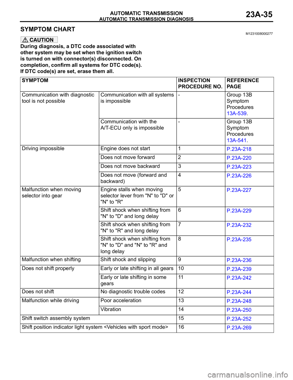
SYMPTOM CHART M1231008000277
During diagnosis, a DTC code associated with
other system may be set when the ignition switch
is turned on with connector(s) disconnected. On
completion, confirm all systems for DTC code(s).
If DTC code(s) are set, erase them all.
SYMPTOM INSPECTION
PROCEDURE NO.REFERENCE
PA G E
Communication with diagnostic
tool is not possibleCommunication with all systems
is impossible- Group 13B
Symptom
Procedures
13A-539.
Communication with the
A/T-ECU only is impossible- Group 13B
Symptom
Procedures
13A-541.
Driving impossible Engine does not start 1
P.23A-218
Does not move forward 2
P.23A-220
Does not move backward 3
P.23A-223
Does not move (forward and
backward)4
P.23A-226
Malfunction when moving
selector into gearEngine stalls when moving
selector lever from "N" to "D" or
"N" to "R"5
P.23A-227
Shift shock when shifting from
"N" to "D" and long delay6
P.23A-229
Shift shock when shifting from
"N" to "R" and long delay 7
P.23A-232
Shift shock when shifting from
"N" to "D" and "N" to "R" and
long delay 8
P.23A-235
Malfunction when shifting Shift shock and slipping 9
P.23A-236
Does not shift properly Early or late shifting in all gears 10
P.23A-239
Early or late shifting in some
gears11
P.23A-242
Does not shift No diagnostic trouble codes 12
P.23A-244
Malfunction while driving Poor acceleration 13
P.23A-248
Vibration 14
P.23A-250
Shift switch assembly system 15
P.23A-252
Shift position indicator light system
P.23A-269