Page 511 of 1500
FRONT SEAT ASSEMBLY
INTERIOR52A-22
INSTALLATION SERVICE POINT
.
>>A<< FRONT SEAT ASSEMBLY INSTALLATION
Install the front passenger's seat assembly before install-
ing the outer seat belt.
1. Temporarily tighten the nuts in mounting locations shown in
the illustration with no weight on the front seat cushion and
check the operation of the seat slide.
2. Temporarily tighten the bolts in mounting locations shown in
the illustration with no weight on the front seat cushion.
3. Tighten the nuts and bolts in all mounting locations to the
specified torque.
Page 869 of 1500
Page 872 of 1500
Page 875 of 1500
REFRIGERANT LINE
HEATER, AIR CONDITIONING AND VENTILATION55-174
3. Ensure a complete mating of joint before tightening the bolts
or nut.
4. Tighten the joint to the specific torque. For the nut joint, pay
special attention to following cautions.
Always use two wrenches to prevent the tubes from twist-
ing.
Pipes will rotate 15 - 20 clockwise during tightening, so
ensure final position is the correct location.
When finally tightening the pipes, do not rotate the fixed
side(female side).
Page 943 of 1500
ON-VEHICLE SERVICE
ENGINE COOLING14-28
2. Drain the water in the water jacket by unplugging the drain
plug of the cylinder block.
3. Remove the radiator condenser tank assembly and drain the
coolant.
4. Drain the coolant then clean the path of the coolant by
injecting water into the radiator from the radiator cap area.
5. Apply the designated sealant to the screw area of the
cylinder block drain plug, and then tighten to the standard
torque.
Specified sealant: 3M
AAD Part No.8731 or equiva-
lent
Tightening torque:
39
5 Nm
6. Securely tighten the radiator drain plug.
7. Assemble the radiator condenser tank assembly.
Page 956 of 1500
WATER HOSE AND WATER PIPE
ENGINE COOLING14-41
INSTALLATION SERVICE POINTS
.
>>A<< O-RING INSTALLATION
Do not allow engine oil or other grease to adhere to the
O-ring
Insert the O-ring to the water pipe, and coat the outer portion of
the O-ring with water or engine coolant.
.
>>B<< ENGINE COOLANT TEMPERATURE
SENSOR INSTALLATION
Apply the specified sealant to the thread of the engine coolant
temperature sensor, and then tighten it to the specified torque.
Specified Sealant: 3M
AAD Part No. 8731 or equiva-
lent
.
>>C<< RADIATOR UPPER HOSE CONNECTION
1. Insert each hose as far as the projection of the water outlet
fitting.
2. Align the mating marks on the radiator hose and hose
clamp, and then connect the radiator hose.
INSPECTIONM1141003400337.
Water Pipe and Hose Check
Check the water pipe and hose for cracks, damage and clogs.
Replace them if necessary.
Page 967 of 1500
Page 1029 of 1500

CROSSMEMBER
POWER PLANT MOUNT32-12
<> SELF LOCKING NUTS (CONNECTION FOR
TIE ROD END AND LOWER ARM BALL JOINT)
REMOVAL
Do not remove the nut from ball joint. Loosen it and use
special tool MB991897 to avoid possible damage to ball
joint threads.
Hang special tool MB991897 with a cord to prevent it
from falling.
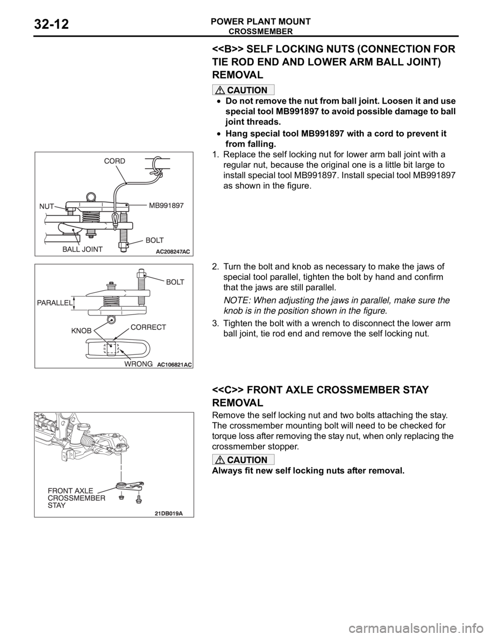
1. Replace the self locking nut for lower arm ball joint with a
regular nut, because the original one is a little bit large to
install special tool MB991897. Install special tool MB991897
as shown in the figure.
2. Turn the bolt and knob as necessary to make the jaws of
special tool parallel, tighten the bolt by hand and confirm
that the jaws are still parallel.
NOTE: When adjusting the jaws in parallel, make sure the
knob is in the position shown in the figure.
3. Tighten the bolt with a wrench to disconnect the lower arm
ball joint, tie rod end and remove the self locking nut.
.
<> FRONT AXLE CROSSMEMBER STAY
REMOVAL
Remove the self locking nut and two bolts attaching the stay.
The crossmember mounting bolt will need to be checked for
torque loss after removing the stay nut, when only replacing the
crossmember stopper.
Always fit new self locking nuts after removal.
.