Page 1097 of 1500
DOOR
BODY42-30
ON-VEHICLE SERVICE
DOOR FIT ADJUSTMENTM1423001100380
Required Special Tools:
MB990211: Slide Hammer
MB990243: Body Puller
MB990900 or MB991164: Door adjusting Wrench
MB990939: Brass Bar
Attach protection tape to the fender and door edges
where the hinge is installed.
Do not rotate special tool MB991164 with a torque of
over 98 N
m (72 ft-lb).
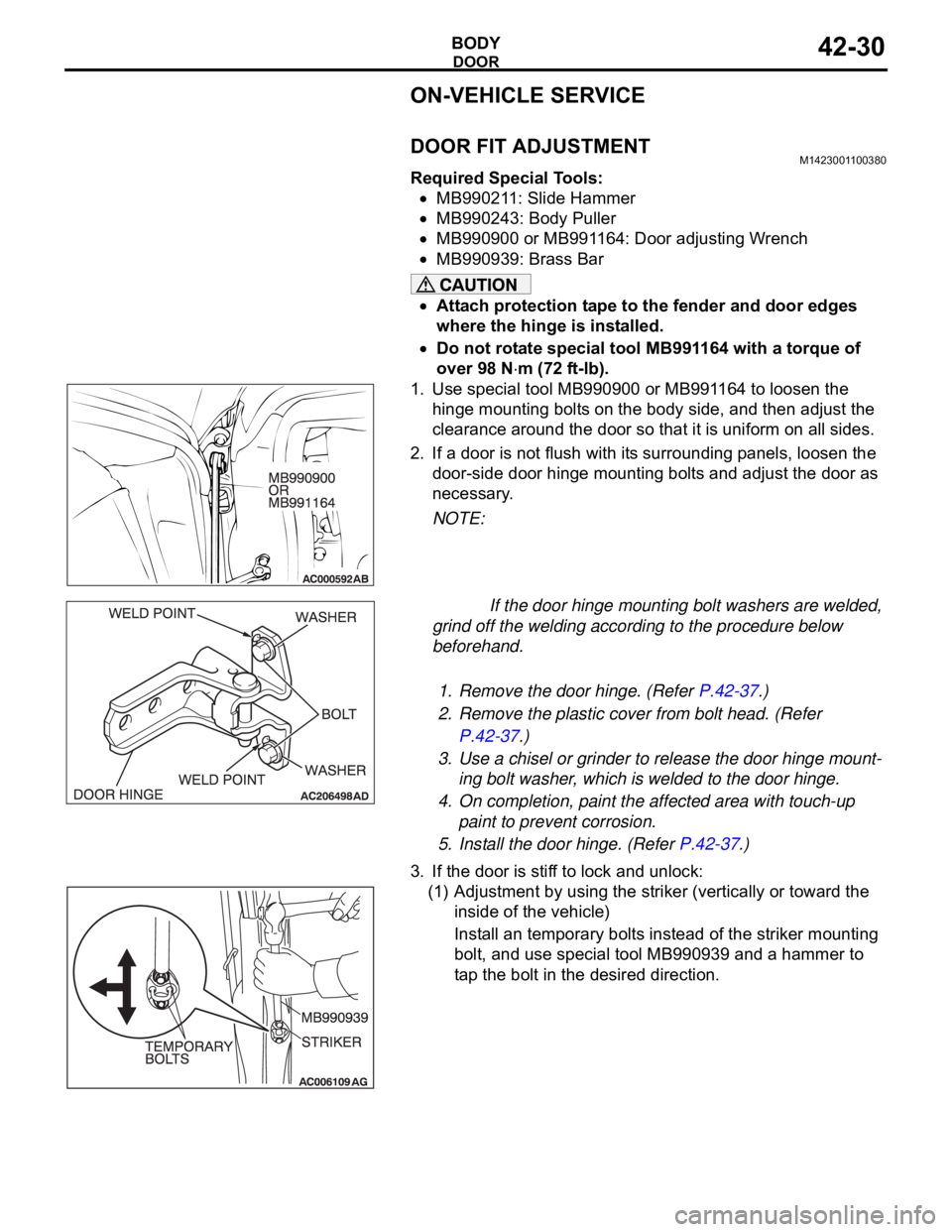
1. Use special tool MB990900 or MB991164 to loosen the
hinge mounting bolts on the body side, and then adjust the
clearance around the door so that it is uniform on all sides.
2. If a door is not flush with its surrounding panels, loosen the
door-side door hinge mounting bolts and adjust the door as
necessary.
NOTE:
If the door hinge mounting bolt washers are welded,
grind off the welding according to the procedure below
beforehand.
.
1. Remove the door hinge. (Refer P.42-37.)
2. Remove the plastic cover from bolt head. (Refer
P.42-37.)
3. Use a chisel or grinder to release the door hinge mount-
ing bolt washer, which is welded to the door hinge.
4. On completion, paint the affected area with touch-up
paint to prevent corrosion.
5. Install the door hinge. (Refer P.42-37.)
3. If the door is stiff to lock and unlock:
(1) Adjustment by using the striker (vertically or toward the
inside of the vehicle)
Install an temporary bolts instead of the striker mounting
bolt, and use special tool MB990939 and a hammer to
tap the bolt in the desired direction.
Page 1158 of 1500
ON-VEHICLE SERVICE
CLUTCH21A-3
Do not push in the master cylinder pushrod at
this time, otherwise the clutch will not operate
properly.
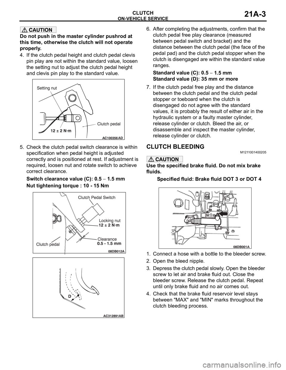
4. If the clutch pedal height and clutch pedal clevis
pin play are not within the standard value, loosen
the setting nut to adjust the clutch pedal height
and clevis pin play to the standard value.
5. Check the clutch pedal switch clearance is within
specification when pedal height is adjusted
correctly and is positioned at rest. If adjustment is
required, loosen nut and rotate switch to achieve
correct clearance.
Switch clearance value (C): 0.5
1.5 mm
Nut tightening torque : 10 - 15 Nm6. After completing the adjustments, confirm that the
clutch pedal free play clearance (measured
between pedal switch and bracket) and the
distance between the clutch pedal (the face of the
pedal pad) and the clutch pedal stopper when the
clutch is disengaged are within the standard value
ranges.
Standard value (C): 0.5
1.5 mm
Standard value (D): 35 mm or more
7. If the clutch pedal free play and the distance
between the clutch pedal and the clutch pedal
stopper or toeboard when the clutch is
disengaged do not agree with the standard
values, it is probably the result of either air in the
hydraulic system or a faulty master cylinder,
release cylinder or clutch. Bleed the air, or
disassemble and inspect the master cylinder,
release cylinder or clutch.
CLUTCH BLEEDINGM1211001400205
Use the specified brake fluid. Do not mix brake
fluids.
Specified fluid: Brake fluid DOT 3 or DOT 4
1. Connect a hose with a bottle to the bleeder screw.
2. Open the bleed nipple.
3. Depress the clutch pedal slowly. Open the bleeder
screw to let air and brake fluid out. Close the
bleeder screw. Release the clutch pedal. Repeat
until only brake fluid and no air comes out.
4. Check that the brake fluid reservoir level stays
between "MAX" and "MIN" marks throughout the
clutch bleeding process.
Page 1161 of 1500
Page 1184 of 1500
ON-VEHICLE SERVICE
BASIC BRAKE SYSTEM35A-19
3. Remove the following parts from the caliper support.
(1) Pad assembly
(2) Clip
4. In order to measure the brake drag force after pad
installation, measure the rotary-sliding resistance of the hub
with the pads removed (Refer to P.35A-30).
5. Install the pads and caliper assembly, and then check the
brake drag force (Refer to P.35A-30).
6. Tighten lock pin bolt. Ensure lock pin is held with spanner
while tightening lock pin bolt(Rear) to specified torque.
DISC BRAKE ROTOR CHECKM1351002900334
Disc brakes must be kept within the allowable
service values in order to maintain normal brake
operation.
Before turning the brake disc, the following condi-
tions should be checked.
Page 1186 of 1500
ON-VEHICLE SERVICE
BASIC BRAKE SYSTEM35A-21
After a new brake disc is installed, always grind the
brake disc with an on-the-car type brake lathe. If this
step is not carried out, the brake disc run-out exceeds
the specified value, resulting in judder.
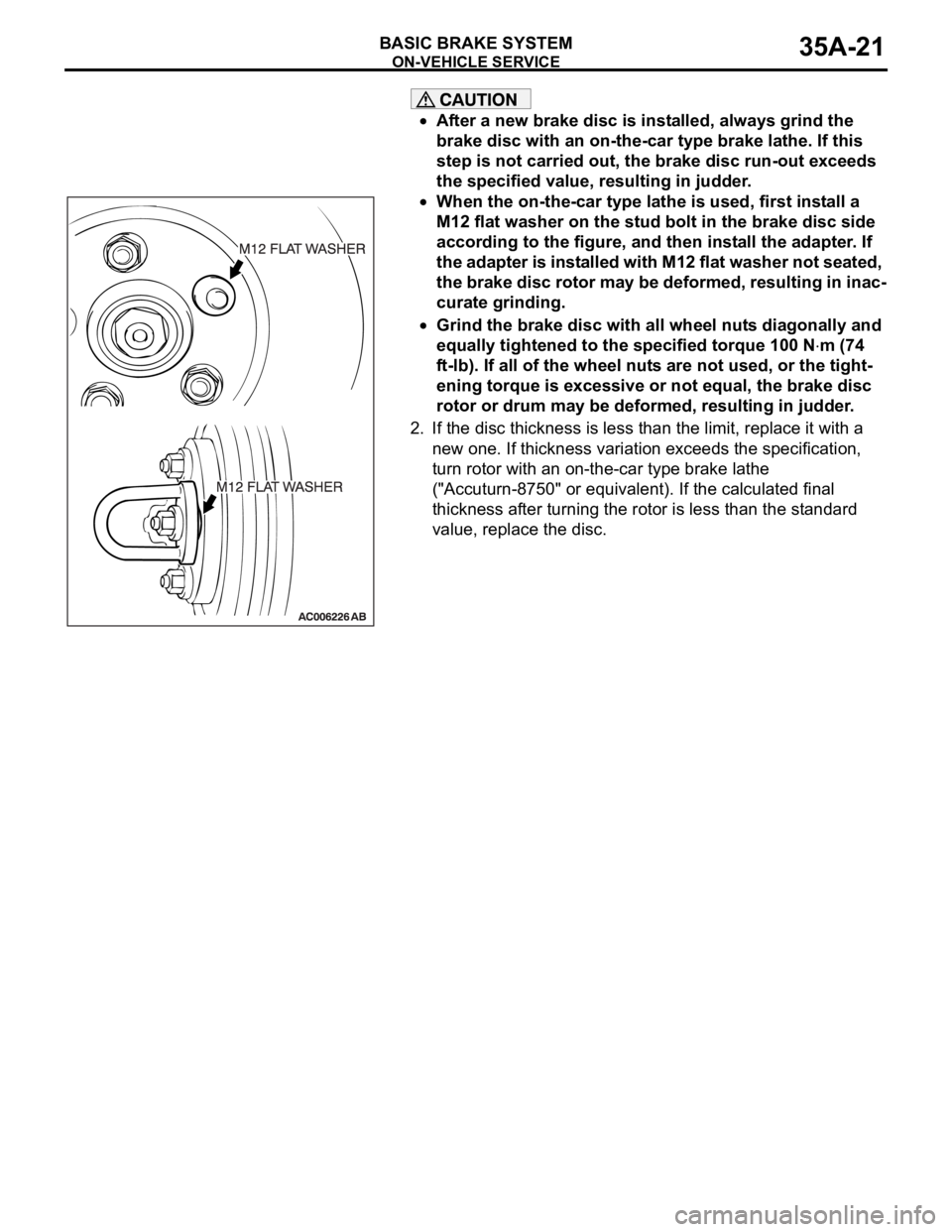
When the on-the-car type lathe is used, first install a
M12 flat washer on the stud bolt in the brake disc side
according to the figure, and then install the adapter. If
the adapter is installed with M12 flat washer not seated,
the brake disc rotor may be deformed, resulting in inac-
curate grinding.
Grind the brake disc with all wheel nuts diagonally and
equally tightened to the specified torque 100 N
m (74
ft-lb). If all of the wheel nuts are not used, or the tight-
ening torque is excessive or not equal, the brake disc
rotor or drum may be deformed, resulting in judder.
2. If the disc thickness is less than the limit, replace it with a
new one. If thickness variation exceeds the specification,
turn rotor with an on-the-car type brake lathe
("Accuturn-8750" or equivalent). If the calculated final
thickness after turning the rotor is less than the standard
value, replace the disc.
.
Page 1188 of 1500
ON-VEHICLE SERVICE
BASIC BRAKE SYSTEM35A-23
After a new brake disc is installed, always grind the
brake disc with an on-the-car type brake lathe. If this
step is not carried out, the brake disc run-out exceeds
the specified value, resulting in judder.
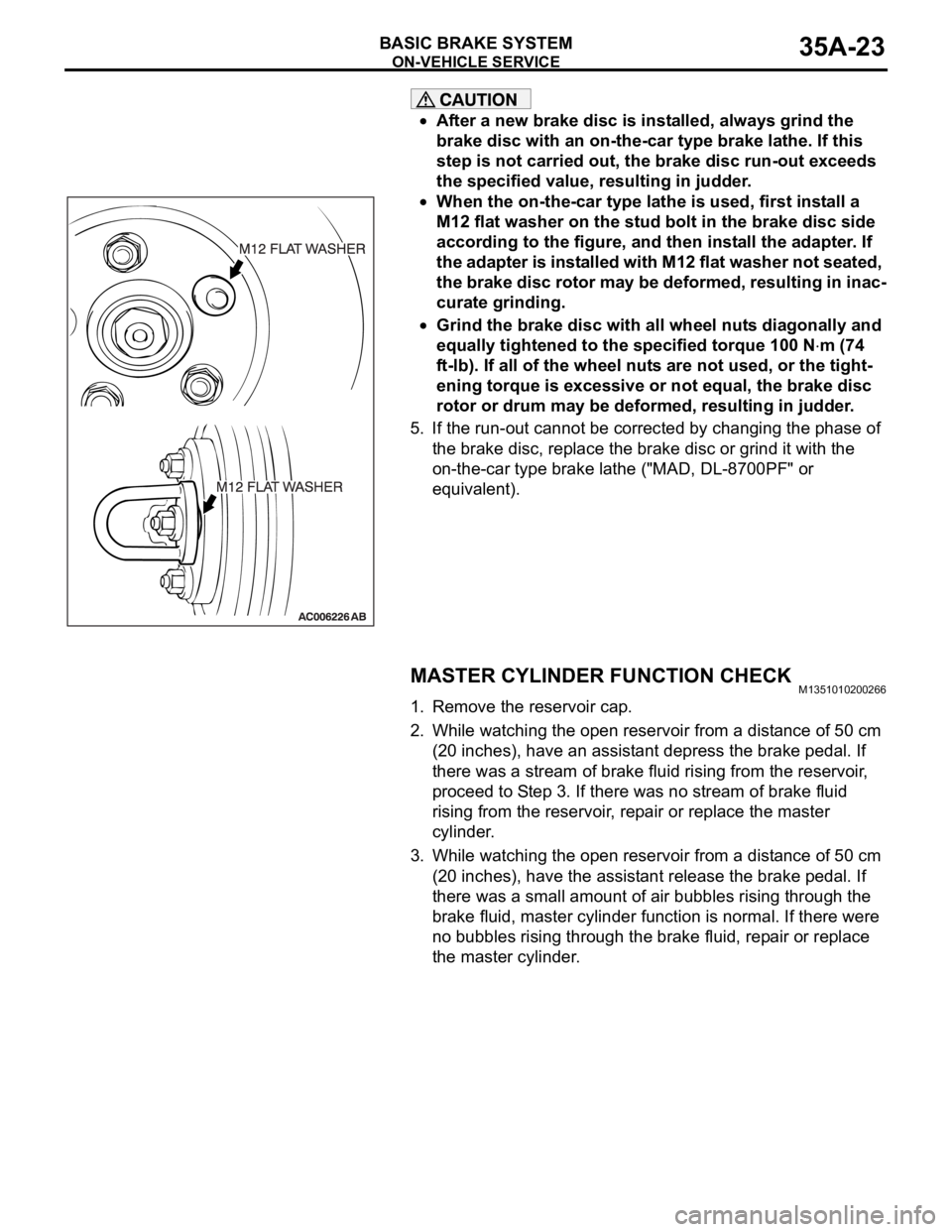
When the on-the-car type lathe is used, first install a
M12 flat washer on the stud bolt in the brake disc side
according to the figure, and then install the adapter. If
the adapter is installed with M12 flat washer not seated,
the brake disc rotor may be deformed, resulting in inac-
curate grinding.
Grind the brake disc with all wheel nuts diagonally and
equally tightened to the specified torque 100 N
m (74
ft-lb). If all of the wheel nuts are not used, or the tight-
ening torque is excessive or not equal, the brake disc
rotor or drum may be deformed, resulting in judder.
5. If the run-out cannot be corrected by changing the phase of
the brake disc, replace the brake disc or grind it with the
on-the-car type brake lathe ("MAD, DL-8700PF" or
equivalent).
MASTER CYLINDER FUNCTION CHECKM1351010200266
1. Remove the reservoir cap.
2. While watching the open reservoir from a distance of 50 cm
(20 inches), have an assistant depress the brake pedal. If
there was a stream of brake fluid rising from the reservoir,
proceed to Step 3. If there was no stream of brake fluid
rising from the reservoir, repair or replace the master
cylinder.
3. While watching the open reservoir from a distance of 50 cm
(20 inches), have the assistant release the brake pedal. If
there was a small amount of air bubbles rising through the
brake fluid, master cylinder function is normal. If there were
no bubbles rising through the brake fluid, repair or replace
the master cylinder.
Page 1196 of 1500
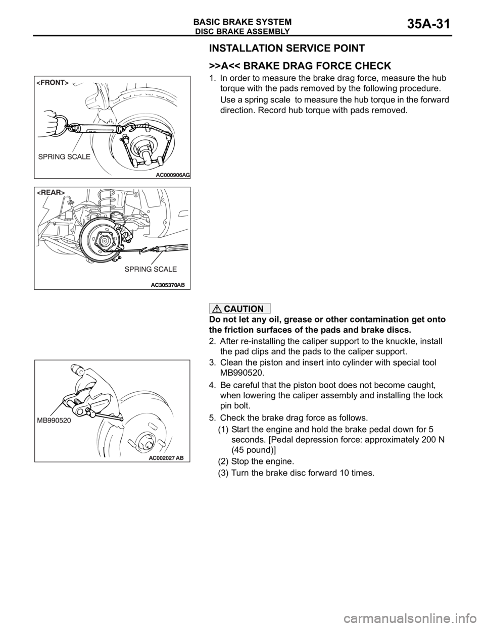
DISC BRAKE ASSEMBLY
BASIC BRAKE SYSTEM35A-31
INSTALLATION SERVICE POINT
.
>>A<< BRAKE DRAG FORCE CHECK
1. In order to measure the brake drag force, measure the hub
torque with the pads removed by the following procedure.
Use a spring scale to measure the hub torque in the forward
direction. Record hub torque with pads removed.
Do not let any oil, grease or other contamination get onto
the friction surfaces of the pads and brake discs.
2. After re-installing the caliper support to the knuckle, install
the pad clips and the pads to the caliper support.
3. Clean the piston and insert into cylinder with special tool
MB990520.
4. Be careful that the piston boot does not become caught,
when lowering the caliper assembly and installing the lock
pin bolt.
5. Check the brake drag force as follows.
(1) Start the engine and hold the brake pedal down for 5
seconds. [Pedal depression force: approximately 200 N
(45 pound)]
(2) Stop the engine.
(3) Turn the brake disc forward 10 times.
Page 1197 of 1500
DISC BRAKE ASSEMBLY
BASIC BRAKE SYSTEM35A-32
(4) Use a spring scale to measure the hub torque with pads
installed in the same direction as earlier.
(5) Calculate the drag force of the disc brake [difference
between hub torque with pads installed and hub torque
with pads removed].
Standard value:
3.8L engine> 64 N (14 pounds) or less
54 N (12 pounds) or less
6. If the brake drag force exceeds the standard value,
disassemble and clean the piston. Check for corrosion or
worn piston seal, and check the sliding condition of the lock
pin and guide pin.
INSPECTIONM1351008100046.
BRAKE DISC CHECK
Disc wear (Refer to P.35A-19).
Disc run-out (Refer to P.35A-19).