2005 MITSUBISHI 380 oil type
[x] Cancel search: oil typePage 573 of 1500

LUGGAGE COMPARTMENT
CONFIGURATION DIAGRAMS80-24
LUGGAGE COMPARTMENTM1801001500311
F-01 (2-GR) HIGH-MOUNTED STOPLIGHT
F-02 (2) HIGH-MOUNTED STOPLIGHT
F-03 (6) REAR COMBINATION LIGHT (RH)F-05 (2) TRUNK LID LATCH ACTUATOR
ASSEMBLY
F-06 (2) LICENSE PLATE LIGHTS
F-09 (6) REAR COMBINATION LIGHT (LH)
F-10 (2) FUEL DOOR LID ACTUATOR
Page 704 of 1500

GENERAL DESCRIPTION
HEATER, AIR CONDITIONING AND VENTILATION55-3
GENERAL DESCRIPTIONM1552000100351
The heater and cooling units are combined in a sin-
gle unit, which, with the mode film damper and flow
rate control valve in the heater unit, reduces ventila-
tion resistance, increases fan power, and decreases
noise.
SAFETY PRECAUTIONS
Wear safety goggles and gloves when servic-
ing the refrigeration system to prevent
severe damage to eyes and hands.
Because R-134a refrigerant is a hydro fluorocarbon
(HFC) which contains hydrogen atoms in place of
chlorine atoms, it will not cause damage to the ozone
layer.
Ozone filters out harmful radiation from the sun. To
assist in protecting the ozone layer, Mitsubishi
Motors Corporation recommends an R-134a refriger-
ant recycling device.
Refrigerant R-134a is transparent and colorless in
both the liquid and vapor state. Since it has a boiling
point of
29.8C (21.64F) at atmospheric pressure,
it will be a vapor at all normal temperatures and pres-
sures. The vapor is heavier than air, non-flammable,
and non-explosive. The following precautions must
be observed when handling R-134a.
Do not heat R-134a above 40C (104.0F) or it
may catch fire and explode.
R-134a evaporates so rapidly at normal atmospheric
pressures and temperatures that it tends to freeze
anything it contacts. For this reason, extreme care
must be taken to prevent any liquid refrigerant from
contacting the skin and especially the eyes. Always
wear safety goggles when servicing the refrigeration
part of the A/C system. Keep a bottle of sterile min-
eral oil handy when working on the refrigeration sys-
tem.1. If any liquid refrigerant gets into your eyes, use a
few drops of mineral oil to wash them out. R-134a
is rapidly absorbed by the oil.
2. Next, splash your eyes with plenty of cold water.
3. Call your doctor immediately even if irritation has
ceased.
Keep R-134a containers upright when charging
the system.
In most instances, moderate heat is required to bring
the pressure of the refrigerant in its container above
the pressure of the system when charging or adding
refrigerant.
A bucket or large pan of hot water not over 40
C
(104.0
F) is all the heat required for this purpose. Do
not heat the refrigerant container with a blow torch or
any other means that would raise temperature and
pressure above this temperature. Do not weld or
steam-clean on or near the system components or
refrigerant lines.
A leak detector for R-134a should be used to
check for refrigerant gas leaks.
Do not allow liquid refrigerant to touch bright
metal or it will be stained.
When metering R-134a into the refrigeration system,
keep the supply tank or cans in an upright position. If
the refrigerant container is on its side or upside
down, liquid refrigerant will enter the system and
damage the compressor.
Refrigerant will tarnish bright metal and chrome sur-
faces, and in combination with moisture can severely
corrode all metal surfaces. ITEM SPECIFICATION
Heater control assembly Dial type
Compressor 10S17
Compressor Model Swashplate type
Refrigerant and quantity (g) R-134a (HFC-134a), 435
475
Page 879 of 1500

SPECIFICATIONS
HEATER, AIR CONDITIONING AND VENTILATION55-178
SPECIFICATIONS
FASTENER TIGHTENING SPECIFICATIONSM1552012100273
GENERAL SPECIFICATIONSM1552000200262
SERVICE SPECIFICATIONSM1552000300333
LUBRICANTSM1552000400329
ITEM SPECIFICATION
Liquid pipe mounting nut (heater unit side) 4.9
0.9 Nm (43 8 in-lb)
Liquid pipe mounting bolt (condenser side) 4.9
0.9 Nm (44 8 in-lb)
Suction flexible hose mounting nut (compressor side) 25
4 Nm (18 3 ft-lb)
Suction pipe mounting nut (heater unit side) 12
2 Nm (107 17 in-lb)
Suction pipe to suction hose union nut 32
2 Nm
Discharge flexible hose mounting bolt (compressor side) 25
4 Nm (18 3 ft-lb)
Discharge flexible hose mounting nut (condenser side) 12
2 Nm (107 17 in-lb)
ITEM MANUAL AIR CONDITIONING
Heater control Dial type
Air conditioning switch Push-button type
Compressor Type 10S17 (Swashplate type)
Displacement (cm
3)188
Refrigerant Type R134a (HFC-134a)
Amount (grams) 435
475
ITEM STANDARD VALUE
Idle speed r/min 680
50
Idle-up speed r/min 680
50
Air mix damper potentiometer resistance k
1.7 5.0
Air outlet changeover damper potentiometer resistance k
0.8 4.8
Air gap (air conditioning compressor clutch) mm (in) 0.3
0.5 (0.012 0.020)
ITEM SPECIFIED LUBRICANT QUANTITY(ml)
Each connection of refrigerant line ND Oil 8 As required
Compressor refrigerant unit lubricant (ml) ND Oil 8 140
Page 907 of 1500

HOW TO DIAGNOSE
GENERAL
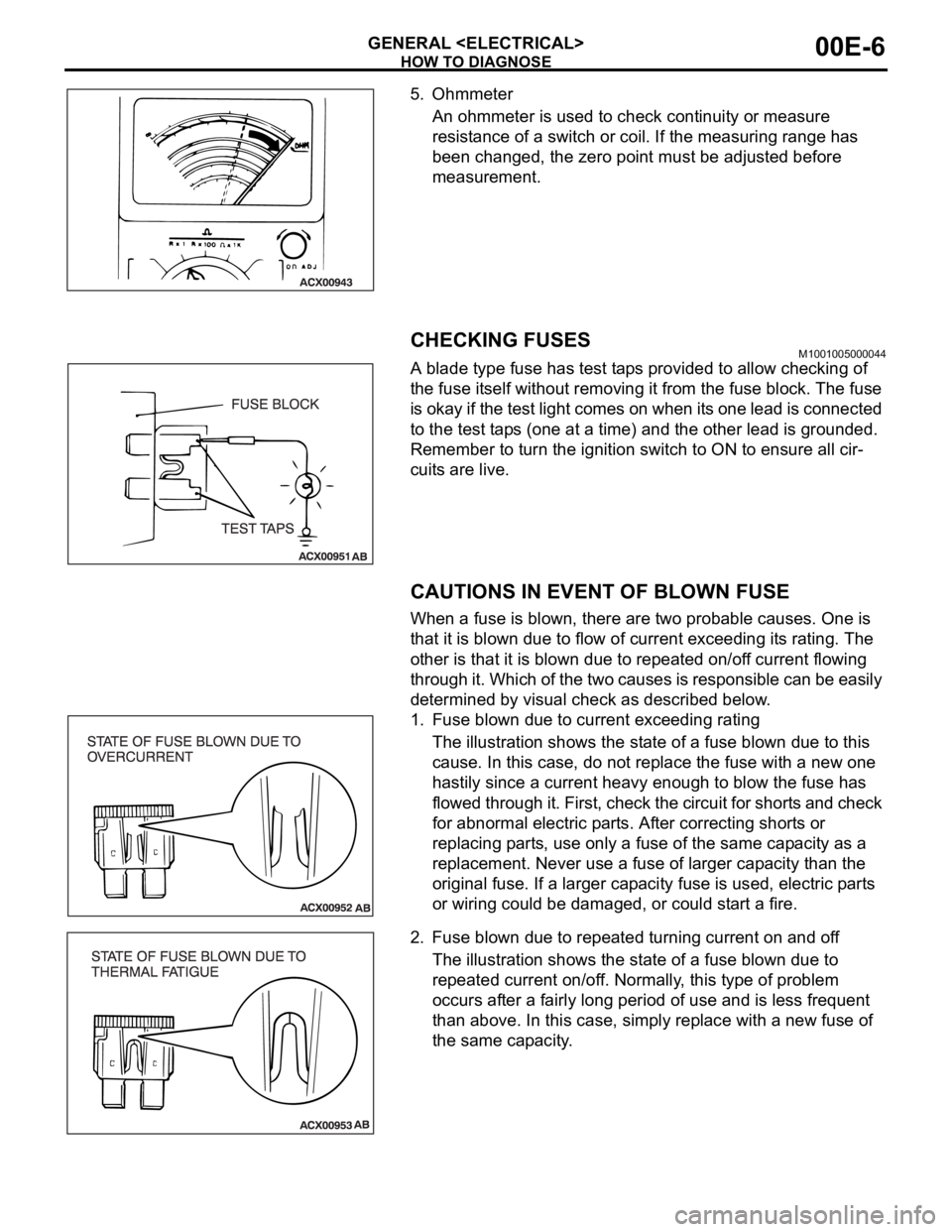
5. Ohmmeter
An ohmmeter is used to check continuity or measure
resistance of a switch or coil. If the measuring range has
been changed, the zero point must be adjusted before
measurement.
CHECKING FUSESM1001005000044
A blade type fuse has test taps provided to allow checking of
the fuse itself without removing it from the fuse block. The fuse
is okay if the test light comes on when its one lead is connected
to the test taps (one at a time) and the other lead is grounded.
Remember to turn the ignition switch to ON to ensure all cir-
cuits are live.
CAUTIONS IN EVENT OF BLOWN FUSE
When a fuse is blown, there are two probable causes. One is
that it is blown due to flow of current exceeding its rating. The
other is that it is blown due to repeated on/off current flowing
through it. Which of the two causes is responsible can be easily
determined by visual check as described below.
1. Fuse blown due to current exceeding rating
The illustration shows the state of a fuse blown due to this
cause. In this case, do not replace the fuse with a new one
hastily since a current heavy enough to blow the fuse has
flowed through it. First, check the circuit for shorts and check
for abnormal electric parts. After correcting shorts or
replacing parts, use only a fuse of the same capacity as a
replacement. Never use a fuse of larger capacity than the
original fuse. If a larger capacity fuse is used, electric parts
or wiring could be damaged, or could start a fire.
2. Fuse blown due to repeated turning current on and off
The illustration shows the state of a fuse blown due to
repeated current on/off. Normally, this type of problem
occurs after a fairly long period of use and is less frequent
than above. In this case, simply replace with a new fuse of
the same capacity.
Page 909 of 1500

HOW TO DIAGNOSE
GENERAL
CHECKING RELAYSM1001004900152
1. By using a relay, a heavy current can be turned on and off by
a switch using much less current. For example, in the circuit
shown here, when the switch is turned on (closed), current
flows to the coil of the relay. Then, its contact is turned on
(closed) and the light comes on. The current flowing through
the switch is much less than that for the light.
2. When current flows through the coil of a relay, its core is
magnetized to attract the iron piece, closing (ON) the
contact at the tip of the iron piece. When the coil current is
turned off, the iron piece returns to its original position by a
spring, opening the contact (OFF).
3. Relays may be classified as the normally open-type or the
normally closed-type, depending on their contact
construction.
NOTE: The deenergised state means that no current is flow-
ing through the coil. The energised state means that current
is flowing through the coil.
(1) The normally open-type
When a normally open relay as illustrated here is
checked, there should be no continuity between terminals
3 and 4 when the relay is deenergised. There should be
continuity between terminals 3 and 4 when battery
voltage and ground are applied to terminals 1 and 2. The
relay condition is determined by this check.
NOTE: Check the relay in both situation which is
energised and is not energised.
(2) The normally closed-type
When a normally closed relay as illustrated here is
checked, there should be continuity between terminals 3
and 4 when the relay is deenergised. There should be no
continuity between terminals 3 and 4 when battery
voltage and ground are applied to terminals 1 and 2. The
relay condition is determined by this check.
NOTE: Check the relay in both situation which is
energised and is not energised.
Page 1015 of 1500

SPECIFICATIONS
ENGINE ELECTRICAL16-38
SPECIFICATIONS
FASTENER TIGHTENING SPECIFICATIONSM1161002100506
GENERAL SPECIFICATIONSM1161000200411
ITEM SPECIFICATION
Charging system
Alternator bracket bolt49
9 Nm (36 7 ft-lb)
Alternator bolt49
9 Nm (36 7 ft-lb)
Alternator terminal nut12
2 Nm (102 22 in-lb)
Ignition system
Camshaft position sensor bolt 11
1 Nm (98 8 in-lb)
Crankshaft position sensor bolt 9.0
1.0 Nm (80 9 in-lb)
Ignition coil bolt 10
2 Nm (89 17 in-lb)
Knock sensor 23
2 Nm (17 1 ft-lb)
Spark plug 25
4 Nm (18 3 ft-lb)
Starting system
Starter bolt 30
3 Nm (23 2 ft-lb)
Starter cover bolt 4.9
1.0 Nm (44 8 in-lb)
Starter terminal nut 12
2 Nm (102 22 in-lb)
ITEMS SPECIFICATIONS
Alternator
Type Positive battery positive voltage sensing
Identification number
Part No. MN180394
Rated output V/A 12/110
Voltage regulator Electronic built-in type
Starter Motor
Type Reduction drive with planetary gear
Identification number M000T31172
Part No. 1810A090
Rated output kW/V 1.2/12
Number of pinion teeth 8
Ignition Coil
Type Molded 6 coil
Spark Plugs
BOSCH FR8DI30
Page 1255 of 1500

LUBRICATION AND MAINTENANCE
GENERAL00-34
LUBRICATION AND MAINTENANCEM1001001200336
Maintenance and lubrication service recommenda-
tions have been compiled to provide maximum pro-
tection for the vehicle owner's investment against all
reasonable types of driving conditions. Since these
conditions vary with the individual vehicle owner's
driving habits, the area in which the vehicle is oper-
ated and the type of driving to which the vehicle is
subjected, it is necessary to prescribe lubrication and
maintenance service on a time frequency as well as
mileage interval basis.
Oils, lubricants and greases are classified and
graded according to standards recommended by the
Society of Automotive Engineers (SAE) and the Aus-
tralian Petroleum Institute (API).
MAINTENANCE SCHEDULES
For Information on service maintenance refer to the
"Service handbook".
ENGINE OIL
Tests have shown that laboratory animals
develop skin cancer after prolonged contact with
used engine oil. Accordingly, the potential exists
for humans to develop a number of skin disor-
ders, including cancer, from such exposure to
used engine oil. Therefore, when changing
engine oil, be careful not to touch it as much as
possible. Protective clothing and gloves, that
cannot be penetrated by oil, should be worn. The
skin should be thoroughly washed with soap and
water, or use waterless hand cleaner, to remove
any used engine oil. Do not use petrol, thinners,
or solvents.Either of the following engine oils should be used:
1. Engine oil conforming to the ACEA classification:
"For service A1, A2 or A3.
2. Engine oil conforming to the API classification:
"For service SG" or higher.
FUEL USAGE STATEMENT
Using leaded petrol in this car will damage the
catalytic converters and heated oxygen sensors,
and affect the warranty coverage validity.
This vehicle must use unleaded petrol only.
This vehicle has a fuel filler tube which is especially
designed to accept only the smaller-diameter
unleaded petrol dispensing nozzle.
The 3.8L model is designed to operate on unleaded
petrol having an octane rating (DIN 51607) of 90
RON or higher.
.
PETROL CONTAINING ALCOHOL
Some petrol sold at service stations contain alcohol
although they may not be so identified.
Using fuels containing alcohol is not recommended
unless the nature of the blend can be determined as
being satisfactory, as follows.
Gasohol: A mixture of 10% ethanol and 90%
unleaded gasoline may be used in your vehicle. If
driveability problems are experienced as a result of
using gasohol, it is recommended that the vehicle be
operated on petrol.
Methanol: Do not use petrol containing methanol
(wood alcohol). Using this type of alcohol can result
in vehicle performance deterioration and damage
critical parts in the fuel system components. Fuel
system damage and performance problems resulting
from the use of petrol containing methanol may not
be covered by the new vehicle warranty.
MATERIALS ADDED TO FUEL
Indiscriminate use of fuel system cleaning agents
should be avoided. Many materials intended for gum
and varnish removal may contain highly active sol-
vents or similar ingredients that can be harmful to
gasket and diaphragm materials used in fuel system
component parts.
Page 1266 of 1500

MAINTENANCE SERVICE
GENERAL00-45
Engine Oil Filter Selection
This vehicle is equipped with a full-flow, throw-away oil filter.
The same type of filter is recommended as a replacement filter
for this vehicle. It is possible, particularly in cold weather, that
this vehicle may develop high oil pressure for a short duration.
Make sure that any replacement filter used on this vehicle is a
high-quality filter. The filter must withstand a pressure of 1,800
kPa (261 psi) [manufacturer's specifications] to avoid filter and
ultimately engine damage. The Genuine Mitsubishi high-quality
filter and is strongly recommended for use on this vehicle.
Any replacement oil filter should be installed in accordance with
the oil filter manufacturer's installation instructions.
.
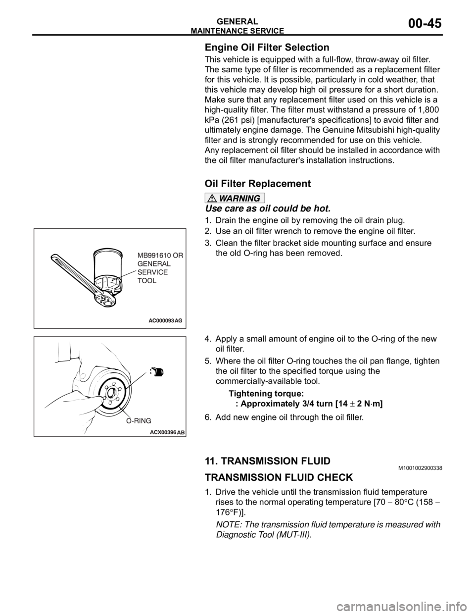
Oil Filter Replacement
Use care as oil could be hot.
1. Drain the engine oil by removing the oil drain plug.
2. Use an oil filter wrench to remove the engine oil filter.
3. Clean the filter bracket side mounting surface and ensure
the old O-ring has been removed.
4. Apply a small amount of engine oil to the O-ring of the new
oil filter.
5. Where the oil filter O-ring touches the oil pan flange, tighten
the oil filter to the specified torque using the
commercially-available tool.
Tightening torque:
: Approximately 3/4 turn [14
2 Nm]
6. Add new engine oil through the oil filler.
11. TRANSMISSION FLUIDM1001002900338
TRANSMISSION FLUID CHECK
1. Drive the vehicle until the transmission fluid temperature
rises to the normal operating temperature [70
80C (158
176
F)].
NOTE: The transmission fluid temperature is measured with
Diagnostic Tool (MUT-III).