Page 972 of 1500
EXHAUST MANIFOLD
INTAKE AND EXHAUST15-13
>>B<< LEFT BANK HEATED OXYGEN SENSOR
(REAR) INSTALLATION
Use special tool MB991953 to install the heated oxygen sensor.
INSPECTIONM1151003400587
Check the following points; replace the part if a problem is
found.
.
Exhaust Manifold Check
1. Check for damage or cracking of any part.
2. Using a straight edge and a feeler gauge, check for
distortion of the cylinder head installation surface.
Standard value: 0.15 mm (0.006 inch) or less
Limit: 0.20 mm (0.008 inch)
Page 973 of 1500
Page 974 of 1500
EXHAUST PIPE AND MAIN MUFFLER
INTAKE AND EXHAUST15-15
INSTALLATION SERVICE POINT
.
>>A<< HEATED OXYGEN SENSOR INSTALLA-
TION
Use special tool MB991953 to install the heated oxygen sensor.
Page 975 of 1500

SPECIFICATIONS
INTAKE AND EXHAUST15-16
SPECIFICATIONS
FASTENER TIGHTENING SPECIFICATIONSM1151006800506
ITEMSPECIFICATION
Air cleaner
Air cleaner bolt 8.8
1.0 Nm (78 9 in-lb)
Air cleaner bracket bolt and nut 12
2 Nm (102 22 in-lb)
Air cleaner resonator bolt 8.8
1.0 Nm (78 9 in-lb)
Air intake hose clamp bolt 4.0
0.9 Nm (35 8 in-lb)
Airflow sensor nut 8.0
1.0 Nm
Exhaust manifold
Exhaust manifold nut 44
5 Nm (33 3 ft-lb)
Front exhaust pipe bolt 49
9 Nm (37 6 ft-lb)
Exhaust manifold stay, left A bolt M8 19
3 Nm (14 2 ft-lb)
Exhaust manifold stay, left B bolt M10 44
8 Nm (33 5 ft-lb)
Heat protector bolt 14
1 Nm (120 13 in-lb)
Heated oxygen sensor 44
5 Nm (33 3 ft-lb)
Exhaust manifold
Exhaust manifold nut 44
5 Nm (33 3 ft-lb)
Exhaust manifold stay, right A bolt M12 75
10 Nm (55 7 ft-lb)
Exhaust manifold stay, right B bolt M10 44
5 Nm (33 3 ft-lb)
Heat protector bolt 14
1 Nm (120 13 in-lb)
Heated oxygen sensor 44
5 Nm (33 3 ft-lb)
Exhaust pipe and main muffler
Crossmember stay bolt 45
5 Nm (34 3 ft-lb)
Center exhaust pipe nut 49
9 Nm (37 6 ft-lb)
Front floor backbone brace bolt 22
4 Nm (16 3 ft-lb)
Front no.1 exhaust pipe bolt 35
4 Nm (26 3 ft-lb)
Front no.1 exhaust pipe to front no.2 exhaust pipe bolt 49
4 Nm (37 3 ft-lb)
Front no.1 exhaust pipe to right bank exhaust manifold nut 49
9 Nm (37 6 ft-lb)
Front no.1 exhaust pipe to left bank exhaust manifold bolt 49
9 Nm (37 6 ft-lb)
Hanger bolt 12
2 Nm (107 17 in-lb)
Main muffler bolt 49
4 Nm (37 3 ft-lb)
Heat protector bolt 14
1 Nm (120 13 in-lb)
Intake manifold
Control harness clamp bolt 11
1 Nm (98 8 in-lb)
Engine mounting stay bolt 36
6 Nm (27 4 ft-lb)
Fuel rail and injector bolt 12
1 Nm (102 13 in-lb)
Intake manifold bolt 22
1 Nm (16 1 ft-lb)
Timing belt front upper cover bolt M6 11
1 Nm (98 8 in-lb)
M8 14
1 Nm (120 13 in-lb)
Page 977 of 1500
SPECIFICATIONS
INTAKE AND EXHAUST15-18
SERVICE SPECIFICATIONM1151000300462
SEALANTSM1151000500187
Intake manifold plenum
Evaporative emission purge solenoid bolt 9.0
1.0 Nm (80 9 in-lb)
Harness bracket bolt 11
1 Nm (98 8 in-lb)
Intake manifold plenum bolt 18
2 Nm (13 2 ft-lb)
Intake manifold plenum stay bolt M8 18
2 Nm (13 2 ft-lb)
M10 36
6 Nm (27 4 ft-lb)
Manifold absolute pressure sensor bolt 5.0
1.0 Nm (44 9 in-lb)
Power steering pressure hose clamp nut 12
2 Nm (102 22 in-lb)
Power steering pressure hose clamp bracket bolt 12
2 Nm (102 22 in-lb)
Power steering oil pump bracket connecting bolt 41
8 Nm (30 6 ft-lb) ITEMSPECIFICATION
ITEM STANDARD VALUE LIMIT
Manifold distortion of the installation surface mm (in) 0.15 (0.006) or less 0.20 (0.008)
ITEM SPECIFIED SEALANT
Thermostat case assembly 3M
AAD Part No.8672, 3M AAD Part No.8679/8678 or
equivalent
Thermostat case assembly bolt 3M
AAD Part No. 8730, 8731 or equivalent
Page 978 of 1500

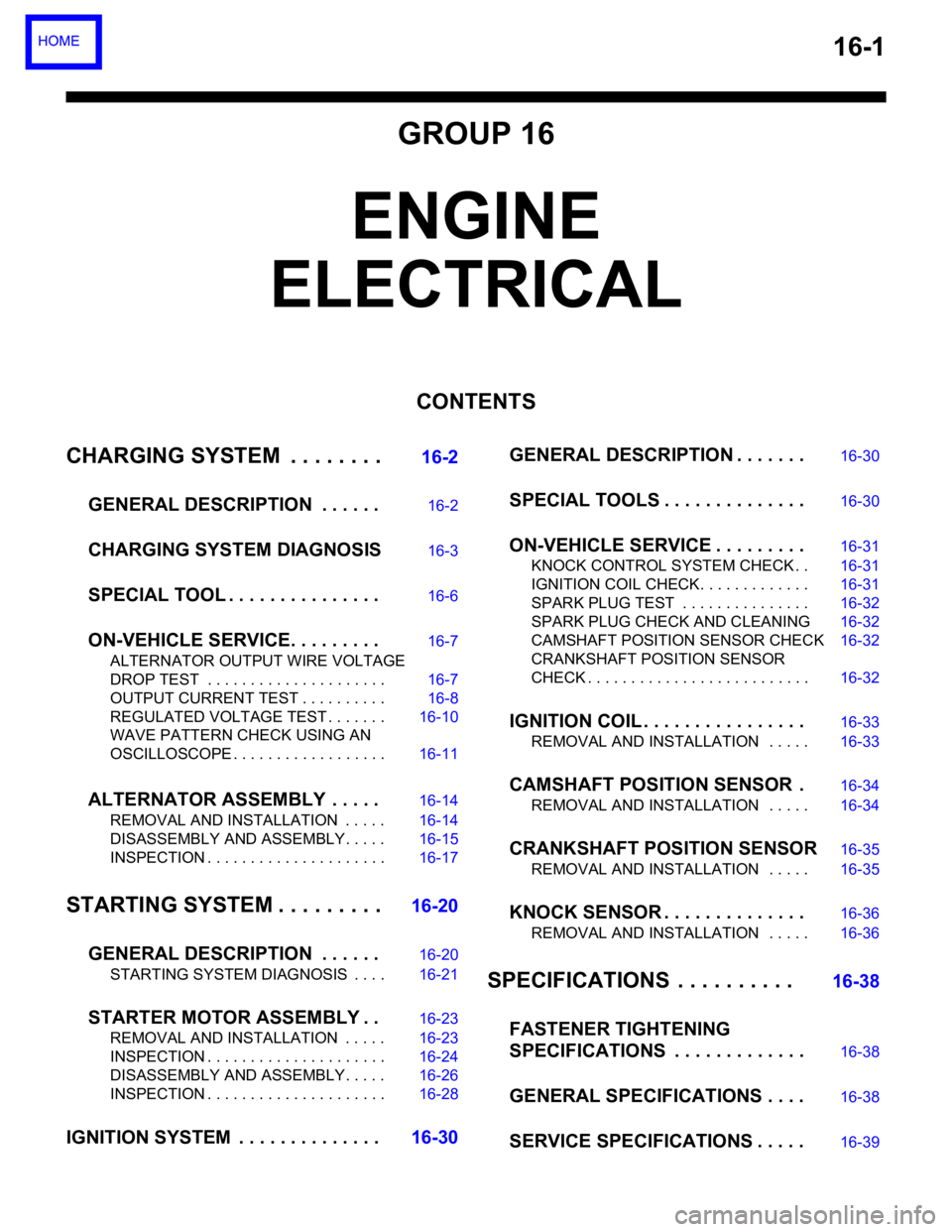
16-1
GROUP 16
ENGINE
ELECTRICAL
CONTENTS
CHARGING SYSTEM . . . . . . . .
16-2
GENERAL DESCRIPTION . . . . . .
16-2
CHARGING SYSTEM DIAGNOSIS16-3
SPECIAL TOOL . . . . . . . . . . . . . . .16-6
ON-VEHICLE SERVICE. . . . . . . . .16-7
ALTERNATOR OUTPUT WIRE VOLTAGE
DROP TEST . . . . . . . . . . . . . . . . . . . . . 16-7
OUTPUT CURRENT TEST . . . . . . . . . . 16-8
REGULATED VOLTAGE TEST . . . . . . . 16-10
WAVE PATTERN CHECK USING AN
OSCILLOSCOPE . . . . . . . . . . . . . . . . . . 16-11
ALTERNATOR ASSEMBLY . . . . .16-14
REMOVAL AND INSTALLATION . . . . . 16-14
DISASSEMBLY AND ASSEMBLY. . . . . 16-15
INSPECTION . . . . . . . . . . . . . . . . . . . . . 16-17
STARTING SYSTEM . . . . . . . . .16-20
GENERAL DESCRIPTION . . . . . .
16-20
STARTING SYSTEM DIAGNOSIS . . . . 16-21
STARTER MOTOR ASSEMBLY . .16-23
REMOVAL AND INSTALLATION . . . . . 16-23
INSPECTION . . . . . . . . . . . . . . . . . . . . . 16-24
DISASSEMBLY AND ASSEMBLY. . . . . 16-26
INSPECTION . . . . . . . . . . . . . . . . . . . . . 16-28
IGNITION SYSTEM . . . . . . . . . . . . . .16-30GENERAL DESCRIPTION . . . . . . .
16-30
SPECIAL TOOLS . . . . . . . . . . . . . .16-30
ON-VEHICLE SERVICE . . . . . . . . .16-31
KNOCK CONTROL SYSTEM CHECK . . 16-31
IGNITION COIL CHECK. . . . . . . . . . . . . 16-31
SPARK PLUG TEST . . . . . . . . . . . . . . . 16-32
SPARK PLUG CHECK AND CLEANING16-32
CAMSHAFT POSITION SENSOR CHECK16-32
CRANKSHAFT POSITION SENSOR
CHECK . . . . . . . . . . . . . . . . . . . . . . . . . . 16-32
IGNITION COIL . . . . . . . . . . . . . . . .16-33
REMOVAL AND INSTALLATION . . . . . 16-33
CAMSHAFT POSITION SENSOR .16-34
REMOVAL AND INSTALLATION . . . . . 16-34
CRANKSHAFT POSITION SENSOR16-35
REMOVAL AND INSTALLATION . . . . . 16-35
KNOCK SENSOR . . . . . . . . . . . . . .16-36
REMOVAL AND INSTALLATION . . . . . 16-36
SPECIFICATIONS . . . . . . . . . . 16-38
FASTENER TIGHTENING
SPECIFICATIONS . . . . . . . . . . . . .
16-38
GENERAL SPECIFICATIONS . . . .16-38
SERVICE SPECIFICATIONS . . . . .16-39
Page 1007 of 1500

IGNITION SYSTEM
ENGINE ELECTRICAL16-30
IGNITION SYSTEM
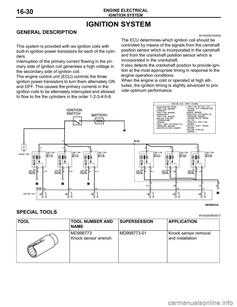
GENERAL DESCRIPTIONM1163000100528
This system is provided with six ignition coils with
built-in ignition power transistors for each of the cylin-
ders.
Interruption of the primary current flowing in the pri-
mary side of ignition coil generates a high voltage in
the secondary side of ignition coil.
The engine control unit (ECU) controls the three
ignition power transistors to turn them alternately ON
and OFF. This causes the primary currents in the
ignition coils to be alternately interrupted and allowed
to flow to fire the cylinders in the order 1-2-3-4-5-6.The ECU determines which ignition coil should be
controlled by means of the signals from the camshaft
position sensor which is incorporated in the camshaft
and from the crankshaft position sensor which is
incorporated in the crankshaft.
It also detects the crankshaft position to provide igni-
tion at the most appropriate timing in response to the
engine operation conditions.
When the engine is cold or operated at high alti-
tudes, the ignition timing is slightly advanced to pro-
vide optimum performance.
SPECIAL TOOLSM1163000600073
TOOL TOOL NUMBER AND
NAMESUPERSESSION APPLICATION
MD998773
Knock sensor wrenchMD998773-01 Knock sensor removal
and installation
Page 1008 of 1500

IGNITION SYSTEM
ENGINE ELECTRICAL16-31
ON-VEHICLE SERVICE
KNOCK CONTROL SYSTEM CHECKM1163001800081
Check the knock sensor circuit if diagnostic trouble code, No.
P0325 is shown.
Refer to GROUP 13B, Multiport Fuel Injection (MPI)
Multiport
Fuel Injection (MPI) Diagnosis
Diagnostic Trouble Code Pro-
cedures
DTC P0325 : Knock Sensor Circuit 13A-346.
IGNITION COIL CHECK M1163001200380
Check by the following procedure, and replace the coil if there
is a malfunction.
.
PRIMARY COIL AND IGNITION POWER
TRANSISTOR CONTINUITY CHECK
NOTE: No test can be performed on the Primary side of coil.
.
SECONDARY COIL CHECK
NOTE: It is impossible to check the secondary coil through the
continuity check as a diode is integrated in the secondary coil
circuit of this ignition coil. Accordingly, check the secondary coil
in the following procedure.
1. Disconnect the ignition coil connector.
2. Remove the ignition coil and install a new spark plug to the
ignition coil.
3. Connect the ignition coil connector.
4. Disable vehicle fuel pump by removing fuel pump relay or
disconnecting fuel pump connector D-18 (under rear seat).
5. Ground the side electrode of the spark plug and crank the
engine.
6. Check that spark is produced between the electrodes of the
spark plug.
7. If no spark is produced, replace the ignition coil with a new
one and recheck.
8. If spark is produced with the new ignition coil, replace the
old one as it is faulty. If no spark is produced again, the
ignition circuit is suspected as faulty. Check the ignition
circuit.