Page 842 of 1500

ON-VEHICLE SERVICE
HEATER, AIR CONDITIONING AND VENTILATION55-141
ON-VEHICLE SERVICE
REFRIGERANT LEVEL TESTM1552008400408
Use the refrigerant recovery station to remove all of the refrig-
erant, and then calculate the amount of the refrigerant and
charge it.
A/C COMPRESSOR CLUTCH TESTM1552019900032
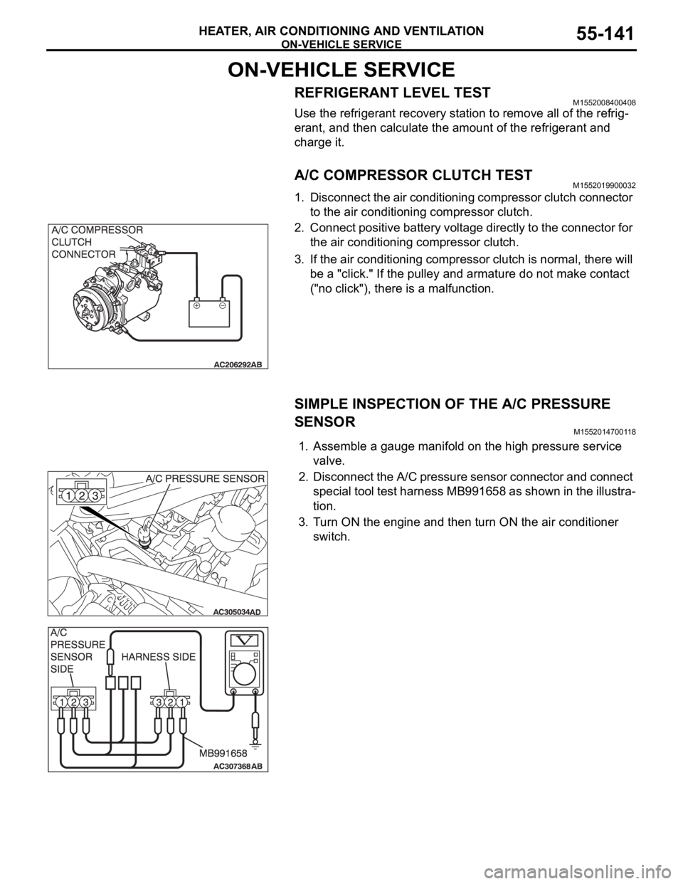
1. Disconnect the air conditioning compressor clutch connector
to the air conditioning compressor clutch.
2. Connect positive battery voltage directly to the connector for
the air conditioning compressor clutch.
3. If the air conditioning compressor clutch is normal, there will
be a "click." If the pulley and armature do not make contact
("no click"), there is a malfunction.
SIMPLE INSPECTION OF THE A/C PRESSURE
SENSOR
M1552014700118
1. Assemble a gauge manifold on the high pressure service
valve.
2. Disconnect the A/C pressure sensor connector and connect
special tool test harness MB991658 as shown in the illustra-
tion.
3. Turn ON the engine and then turn ON the air conditioner
switch.
Page 843 of 1500

ON-VEHICLE SERVICE
HEATER, AIR CONDITIONING AND VENTILATION55-142
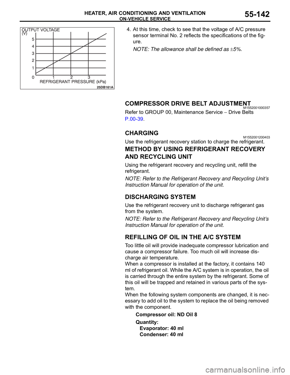
4. At this time, check to see that the voltage of A/C pressure
sensor terminal No. 2 reflects the specifications of the fig-
ure.
NOTE: The allowance shall be defined as
5%.
COMPRESSOR DRIVE BELT ADJUSTMENTM1552001000357
Refer to GROUP 00, Maintenance Service Drive Belts
P.00-39.
CHARGING M1552001200403
Use the refrigerant recovery station to charge the refrigerant.
METHOD BY USING REFRIGERANT RECOVERY
AND RECYCLING UNIT
Using the refrigerant recovery and recycling unit, refill the
refrigerant.
NOTE: Refer to the Refrigerant Recovery and Recycling Unit’s
Instruction Manual for operation of the unit.
DISCHARGING SYSTEM
Use the refrigerant recovery unit to discharge refrigerant gas
from the system.
NOTE: Refer to the Refrigerant Recovery and Recycling Unit’s
Instruction Manual for operation of the unit.
REFILLING OF OIL IN THE A/C SYSTEM
Too little oil will provide inadequate compressor lubrication and
cause a compressor failure. Too much oil will increase dis-
charge air temperature.
When a compressor is installed at the factory, it contains 140
ml of refrigerant oil. While the A/C system is in operation, the oil
is carried through the entire system by the refrigerant. Some of
this oil will be trapped and retained in various parts of the sys-
tem.
When the following system components are changed, it is nec-
essary to add oil to the system to replace the oil being removed
with the component.
Compressor oil: ND Oil 8
Quantity:
Evaporator: 40 ml
Condenser: 40 ml
Page 845 of 1500
ON-VEHICLE SERVICE
HEATER, AIR CONDITIONING AND VENTILATION55-144
REFRIGERANT LEAK INSPECTION PROCEDUREM1552001500299
LEAK INSPECTION
1. Check for leakage using Special Tool at the following loca-
tions.
Good ventilation is necessary during the leak inspection. If
the surrounding air is contaminated with refrigerant gas,
the inspection readings will not be accurate.
LEAK CHECK LOCATION
1. SUCTION HOSE TO TX VALVE
2. LIQUID TUBE TO TX VALVE
3. SUCTION HOSE JOINT
4. LOW PRESSURE SERVICE
VA LV E
5. HIGH PRESSURE SERVICE
VA LV E
6. CONDENSER-DISCHARGE
HOSE JOINT
7. PRESSURE SENSOR8. CONDENSER-LIQUID TUBE
JOINT
9. COMPRESSOR-SUCTION HOSE
JOINT
10. COMPRESSOR-DISCHARGE
HOSE JOINT
11. UNDER COMPRESSOR CLUTCH
12. AROUND MODULATOR CAP
13. TX VALVE TO EVAPORATOR
JOINT LEAK CHECK LOCATION
Page 855 of 1500
HEATER UNIT, HEATER CORE, BLOWER ASSEMBLY AND EVAPORATOR UNIT
HEATER, AIR CONDITIONING AND VENTILATION55-154
DISASSEMBLY AND ASSEMBLYM1551005400365
DISASSEMBLY STEPS
1. PACKING
2. HEATER CORE ASSEMBLY
3. EXPANSION VALVE JOINT
4. EXPANSION VALVE
5. O-RING
6. EVAPORATOR
7. MODE SELECTION DAMPER
CONTROL MOTOR AND
POTENTIOMETER
8. ASPIRATOR
9. ASPIRATOR HOSE
10. AIR THERMO SENSOR CLIP11. AIR THERMO SENSOR
12. FOOT DUCT
13. LEVER A
14. LEVER B
15. LEVER C
16. LEVER D
17. LEVER E
18. HEATER CASE LOWER
19. MODE SELECTION DAMPER
20. MAX A/C DAMPER
21. AIR MIXING DAMPER
22. HEATER CASE UPPERDISASSEMBLY STEPS
Page 856 of 1500

HEATER UNIT, HEATER CORE, BLOWER ASSEMBLY AND EVAPORATOR UNIT
HEATER, AIR CONDITIONING AND VENTILATION55-155
INSPECTIONM1552014301157.
AIR MIXING DAMPER CONTROL MOTOR CHECK
Do not apply battery voltage when the damper is in the
MAX COOL or MAX HOT position.
Check the air mix damper control motor by the following proce-
dures.
.
POTENTIOMETER CHECK
While checking the air mix damper control motor, measure the
resistances between terminals numbers 3 and 5 and between
numbers 3 and 7. At this time, the resistances should change
gradually within the standard value.
Standard value: 1.7 (MAX HOT)
5.0 (MAX COOL) k
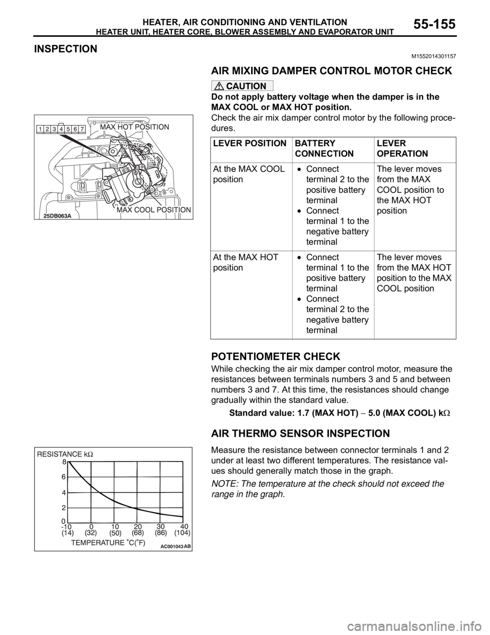
AIR THERMO SENSOR INSPECTION
.Measure the resistance between connector terminals 1 and 2
under at least two different temperatures. The resistance val-
ues should generally match those in the graph.
NOTE: The temperature at the check should not exceed the
range in the graph. LEVER POSITION BATTERY
CONNECTIONLEVER
OPERATION
At the MAX COOL
position
Connect
terminal 2 to the
positive battery
terminal
Connect
terminal 1 to the
negative battery
terminalThe lever moves
from the MAX
COOL position to
the MAX HOT
position
At the MAX HOT
position
Connect
terminal 1 to the
positive battery
terminal
Connect
terminal 2 to the
negative battery
terminalThe lever moves
from the MAX HOT
position to the MAX
COOL position
Page 861 of 1500
SENSORS
HEATER, AIR CONDITIONING AND VENTILATION55-160
SENSORS
REMOVAL AND INSTALLATIONM1554001900088
Required Special Tools:
: Diagnostic Tool (MUT-III Sub Assembly)
MB991824: Vehicle Communication Interface
(V.C.I.)
MB991827: MUT-III USB Cable
MB991910: MUT-III Main Harness A
INTERIOR TEMPERATURE
SENSOR REMOVAL STEPS
LOWER PANEL (REFER TO
GROUP 52A, INSTRUMENT
PA N E L P.52A-4).
1. INTERIOR TEMPERATURE
SENSOR
2. ASPIRATOR HOSEPHOTO SENSOR REMOVAL
STEPS
3. PHOTO SENSOR
Page 862 of 1500
SENSORS
HEATER, AIR CONDITIONING AND VENTILATION55-161
INSPECTIONM1554002000130.
INTERIOR TEMPERATURE SENSOR CHECK
When the resistance between the sensor terminals is mea-
sured under two or more temperature conditions, the resis-
tance should approximately satisfy the illustrated values.
NOTE:
The temperature conditions when checking should not
exceed the range shown in the diagram.
.
PHOTO SENSOR CHECK
1. Connect diagnostic tool , and check the data list of the
photo sensor. (Refer to P.55-133)
2. Check that the displayed value changes when you cover
the photo sensor with your hands.
Page 863 of 1500