Page 1493 of 1500

AUTOMATIC TRANSMISSION DIAGNOSIS
AUTOMATIC TRANSMISSION23A-34
DIAGNOSTIC TROUBLE CODE CHARTM1231007900330
During diagnosis, a DTC code associated with
other system may be set when the ignition switch
is turned on with connector(s) disconnected. On
completion, confirm all systems for DTC code(s).
If DTC code(s) are set, erase them all.
NOTE: The A/T diagnostic trouble codes are the codes which are set when item "A/T" is selected on
diagnostic tool MB991958 (MUT-III sub assembly). However, the some codes above indicate failure in the
MPI system.A/T DTC
NO.DIAGNOSIS ITEM REFERENCE
PA G E
P0713 Transmission fluid temperature sensor system Open circuit
P.23A-36
P0712 Short circuit
P.23A-47
P0715 Input shaft speed sensor system Short circuit/open circuit
P.23A-55
P0720 Output shaft speed sensor system Short circuit/open circuit
P.23A-72
Stoplamp switch systemShort circuit
P.23A-89
P0705 Transmission range switch system Open circuit
P.23A-97
Short circuit
P.23A-119
P0753 Low-reverse solenoid valve system Short circuit/open circuit
P.23A-133
P0758 Underdrive solenoid valve system Short circuit/open circuit
P.23A-144
P0763 Second solenoid valve system Short circuit/open circuit
P.23A-154
P0768 Overdrive solenoid valve system Short circuit/open circuit
P.23A-164
P0773 Reduction (RED) solenoid valve system Short circuit/open circuit
P.23A-174
P0743 Damper clutch control (DCC) solenoid valve
systemShort circuit/open circuit
P.23A-185
P0731 1st gear incorrect ratio
P.23A-196
P0732 2nd gear incorrect ratio
P.23A-196
P0733 3rd gear incorrect ratio
P.23A-196
P0734 4th gear incorrect ratio
P.23A-196
P0735 5th gear incorrect ratio
P.23A-196
P0736 Reverse gear incorrect ratio
P.23A-196
P0741 Damper clutch control (DCC) system Defective system
P.23A-201
P0742 Clutch stuck on
P.23A-204
P1751 A/T control relay system Short circuit to ground/open
circuitP.23A-207
Page 1495 of 1500
AUTOMATIC TRANSMISSION DIAGNOSIS
AUTOMATIC TRANSMISSION23A-36
DIAGNOSTIC TROUBLE CODE PROCEDURES
(P0713): Transmission Fluid Temperature Sensor System (Open Circuit)
.
CIRCUIT OPERATION
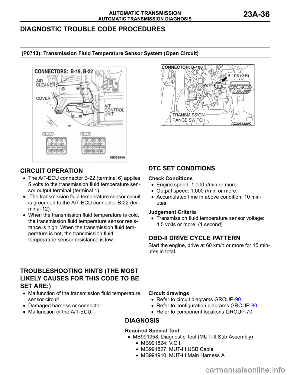
The A/T-ECU connector B-22 (terminal 6) applies
5 volts to the transmission fluid temperature sen-
sor output terminal (terminal 1).
The transmission fluid temperature sensor circuit
is grounded to the A/T-ECU connector B-22 (ter-
minal 12).
When the transmission fluid temperature is cold,
the transmission fluid temperature sensor resis-
tance is high. When the transmission fluid tem-
perature is hot, the transmission fluid
temperature sensor resistance is low.
.
DTC SET CONDITIONS
Check Conditions
Engine speed: 1,000 r/min or more.
Output speed: 1,000 r/min or more.
Accumulated time in above condition: 10 min-
utes.
Judgement Criteria
Transmission fluid temperature sensor voltage:
4.5 volts or more. (1 second)
.
OBD-II DRIVE CYCLE PATTERN
Start the engine, drive at 60 km/h or more for 15 min-
utes in total.
.
TROUBLESHOOTING HINTS (THE MOST
LIKELY CAUSES FOR THIS CODE TO BE
SET ARE:)
Malfunction of the transmission fluid temperature
sensor circuit
Damaged harness or connector
Malfunction of the A/T-ECUCircuit drawings
Refer to circuit diagrams GROUP-90
Refer to configuration diagrams GROUP-80
Refer to component locations GROUP-70
DIAGNOSIS
Required Special Tool:
MB991958: Diagnostic Tool (MUT-III Sub Assembly)
MB991824: V.C.I.
MB991827: MUT-III USB Cable
MB991910: MUT-III Main Harness A
Page 1496 of 1500
AUTOMATIC TRANSMISSION DIAGNOSIS
AUTOMATIC TRANSMISSION23A-37
STEP 1. Using diagnostic tool MB991958, check data list
item 7: Transmission Fluid Temperature Sensor.
To prevent damage to diagnostic tool MB991958, always
turn the ignition switch to the "LOCK" (OFF) position
before connecting or disconnecting diagnostic tool
MB991958.
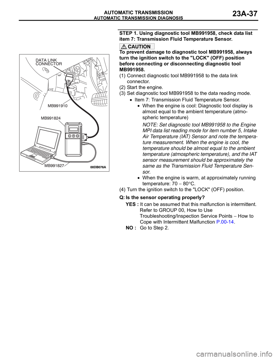
(1) Connect diagnostic tool MB991958 to the data link
connector.
(2) Start the engine.
(3) Set diagnostic tool MB991958 to the data reading mode.
Item 7: Transmission Fluid Temperature Sensor.
When the engine is cool: Diagnostic tool display is
almost equal to the ambient temperature (atmo-
spheric temperature)
NOTE: Set diagnostic tool MB991958 to the Engine
MPI data list reading mode for item number 5, Intake
Air Temperature (IAT) Sensor and note the tempera-
ture measurement. When the engine is cool, the
temperature should be almost equal to the ambient
temperature (atmospheric temperature), and the IAT
sensor measurement should be approximately the
same as the Transmission Fluid Temperature Sen-
sor.
When the engine is warm, at approximately running
temperature: 70
80C.
(4) Turn the ignition switch to the "LOCK" (OFF) position.
Q: Is the sensor operating properly?
YES : It can be assumed that this malfunction is intermittent.
Refer to GROUP 00, How to Use
Troubleshooting/Inspection Service Points
How to
Cope with Intermittent Malfunction P.00-14.
NO : Go to Step 2.
Page 1497 of 1500
AUTOMATIC TRANSMISSION DIAGNOSIS
AUTOMATIC TRANSMISSION23A-38
STEP 2. Measure the sensor output voltage at the A/T
control solenoid valve assembly connector B-108 by
backprobing.
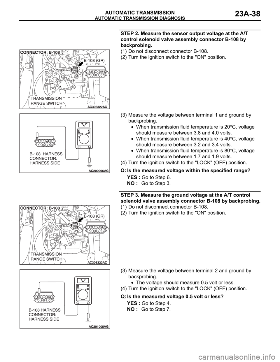
(1) Do not disconnect connector B-108.
(2) Turn the ignition switch to the "ON" position.
(3) Measure the voltage between terminal 1 and ground by
backprobing.
When transmission fluid temperature is 20C, voltage
should measure between 3.8 and 4.0 volts.
When transmission fluid temperature is 40C, voltage
should measure between 3.2 and 3.4 volts.
When transmission fluid temperature is 80C, voltage
should measure between 1.7 and 1.9 volts.
(4) Turn the ignition switch to the "LOCK" (OFF) position.
Q: Is the measured voltage within the specified range?
YES : Go to Step 6.
NO : Go to Step 3.
STEP 3. Measure the ground voltage at the A/T control
solenoid valve assembly connector B-108 by backprobing.
(1) Do not disconnect connector B-108.
(2) Turn the ignition switch to the "ON" position.
(3) Measure the voltage between terminal 2 and ground by
backprobing.
The voltage should measure 0.5 volt or less.
(4) Turn the ignition switch to the "LOCK" (OFF) position.
Q: Is the measured voltage 0.5 volt or less?
YES : Go to Step 4.
NO : Go to Step 7.
Page 1498 of 1500
AUTOMATIC TRANSMISSION DIAGNOSIS
AUTOMATIC TRANSMISSION23A-39
STEP 4. Check the sensor output voltage at A/T control
solenoid valve assembly connector B-108.
(1) Disconnect connector B-108 and measure at the harness
side.
(2) Turn the ignition switch to the "ON" position.
(3) Measure the voltage between terminal 1 and ground.
The voltage should measure between 4.5 and 4.9 volts.
(4) Turn the ignition switch to the "LOCK" (OFF) position.
Q: Is the measured voltage between 4.5 and 4.9 volts?
YES : Go to Step 5.
NO : Go to Step 9.
Page 1499 of 1500
AUTOMATIC TRANSMISSION DIAGNOSIS
AUTOMATIC TRANSMISSION23A-40
STEP 5. Check the transmission fluid temperature sensor
at A/T control solenoid valve assembly connector B-108.
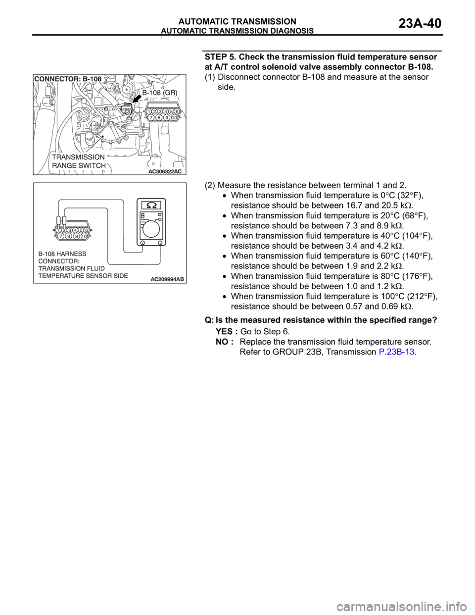
(1) Disconnect connector B-108 and measure at the sensor
side.
(2) Measure the resistance between terminal 1 and 2.
When transmission fluid temperature is 0C (32F),
resistance should be between 16.7 and 20.5 k
.
When transmission fluid temperature is 20C (68F),
resistance should be between 7.3 and 8.9 k
.
When transmission fluid temperature is 40C (104F),
resistance should be between 3.4 and 4.2 k
.
When transmission fluid temperature is 60C (140F),
resistance should be between 1.9 and 2.2 k
.
When transmission fluid temperature is 80C (176F),
resistance should be between 1.0 and 1.2 k
.
When transmission fluid temperature is 100C (212F),
resistance should be between 0.57 and 0.69 k
.
Q: Is the measured resistance within the specified range?
YES : Go to Step 6.
NO : Replace the transmission fluid temperature sensor.
Refer to GROUP 23B, Transmission P.23B-13.
Page 1500 of 1500
AUTOMATIC TRANSMISSION DIAGNOSIS
AUTOMATIC TRANSMISSION23A-41
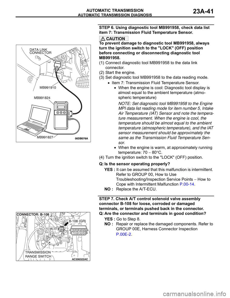
STEP 6. Using diagnostic tool MB991958, check data list
item 7: Transmission Fluid Temperature Sensor.
To prevent damage to diagnostic tool MB991958, always
turn the ignition switch to the "LOCK" (OFF) position
before connecting or disconnecting diagnostic tool
MB991958.
(1) Connect diagnostic tool MB991958 to the data link
connector.
(2) Start the engine.
(3) Set diagnostic tool MB991958 to the data reading mode.
Item 7: Transmission Fluid Temperature Sensor.
When the engine is cool: Diagnostic tool display is
almost equal to the ambient temperature (atmo-
spheric temperature)
NOTE: Set diagnostic tool MB991958 to the Engine
MPI data list reading mode for item number 5, Intake
Air Temperature (IAT) Sensor and note the tempera-
ture measurement. When the engine is cool, the
temperature should be almost equal to the ambient
temperature (atmospheric temperature), and the IAT
sensor measurement should be approximately the
same as the Transmission Fluid Temperature Sen-
sor.
When the engine is warm, at approximately running
temperature: 70
80C.
(4) Turn the ignition switch to the "LOCK" (OFF) position.
Q: Is the sensor operating properly?
YES : It can be assumed that this malfunction is intermittent.
Refer to GROUP 00, How to Use
Troubleshooting/Inspection Service Points
How to
Cope with Intermittent Malfunction P.00-14.
NO : Replace the A/T-ECU.
STEP 7. Check A/T control solenoid valve assembly
connector B-108 for loose, corroded or damaged
terminals, or terminals pushed back in the connector.
Q: Are the connector and terminals in good condition?
YES : Go to Step 8.
NO : Repair or replace the damaged components. Refer to
GROUP 00E, Harness Connector Inspection
P.00E-2.