Page 1407 of 1500

EMISSION CONTROL
ENGINE AND EMISSION CONTROL17-76
EMISSION CONTROL
GENERAL DESCRIPTIONM1173000100314
The emission control system consists of the fol-
lowing subsystems:
Positive crankcase ventilation system
Evaporative emission system
Exhaust emission control system
DIAGNOSISM1173000700112
SPECIAL TOOLSM1173000600193
SYMPTOM PROBABLE CAUSE REMEDY
Engine will not start or hard
to startVacuum hose disconnected or damaged Repair or replace
Malfunction of the evaporative emission
purge solenoidRepair or replace
Rough idle or engine stalls
Vacuum hose disconnected or damaged. Repair or replace
Malfunction of the positive crankcase
ventilation valveReplace
Malfunction of the purge control system Check the system; If there is a
problem, check its component
parts.
Excessive oil consumption Positive crankcase ventilation line
cloggedCheck positive crankcase
ventilation system
TOOL TOOL NUMBER AND
NAMESUPERSESSION APPLICATION
MB995061
Purge flow indicatorMLR6890A
Part of MIT280220Inspection of purge
control system
MD998770
Oxygen sensor wrenchMD998770-01 or General
service toolRemoval/installation of
heated oxygen sensor
Page 1415 of 1500
![MITSUBISHI 380 2005 Workshop Manual EMISSION CONTROL
ENGINE AND EMISSION CONTROL17-84
5. Measure the resistance between the terminals of the EVAP
purge solenoid.
Standard value: 16
[at 20C )]
6. Replace the solenoid if resistance is MITSUBISHI 380 2005 Workshop Manual EMISSION CONTROL
ENGINE AND EMISSION CONTROL17-84
5. Measure the resistance between the terminals of the EVAP
purge solenoid.
Standard value: 16
[at 20C )]
6. Replace the solenoid if resistance is](/manual-img/19/57086/w960_57086-1414.png)
EMISSION CONTROL
ENGINE AND EMISSION CONTROL17-84
5. Measure the resistance between the terminals of the EVAP
purge solenoid.
Standard value: 16
[at 20C )]
6. Replace the solenoid if resistance is out of specification.
MASS AIRFLOW SENSOR CHECKM1173050400053
To inspect these parts, refer to GROUP 13A, Multipoint Fuel
Injection (MPI)
Multipoint Fuel Injection (MPI) Diagnosis
Diagnostic Trouble Code Chart 13A-17.
ENGINE COOLANT TEMPERATURE SENSOR
CHECK
M1173008100523
To inspect the sensor, refer to GROUP 13A, Multipoint Fuel
Injection (MPI)
Multipoint Fuel Injection (MPI) Diagnosis
Diagnostic Trouble Code Chart 13A-17.
INTAKE AIR TEMPERATURE SENSOR CHECKM1173008200263
To inspect the sensor, refer to GROUP 13A, Multipoint Fuel
Injection (MPI)
Multipoint Fuel Injection (MPI) Diagnosis
Diagnostic Trouble Code Chart 13A-17.
CATALYTIC CONVERTER
GENERAL DESCRIPTION (CATALYTIC CONVERTER)M1173005300131
The three way catalytic converter, together with the
closed loop air-fuel ratio control based on the oxygen
sensor signal, oxidizes carbon monoxides (CO) and
hydrocarbons (HC), also reduces nitrogen oxides
(NOx). When the mixture is controlled at stoichiometric
air-fuel ratio, the three way catalytic converter pro-
vides the highest purification against the three con-
stituents, namely, CO, HC and NOx.
Page 1426 of 1500
Page 1430 of 1500

DRIVE SHAFT ASSEMBLY
FRONT AXLE26-13
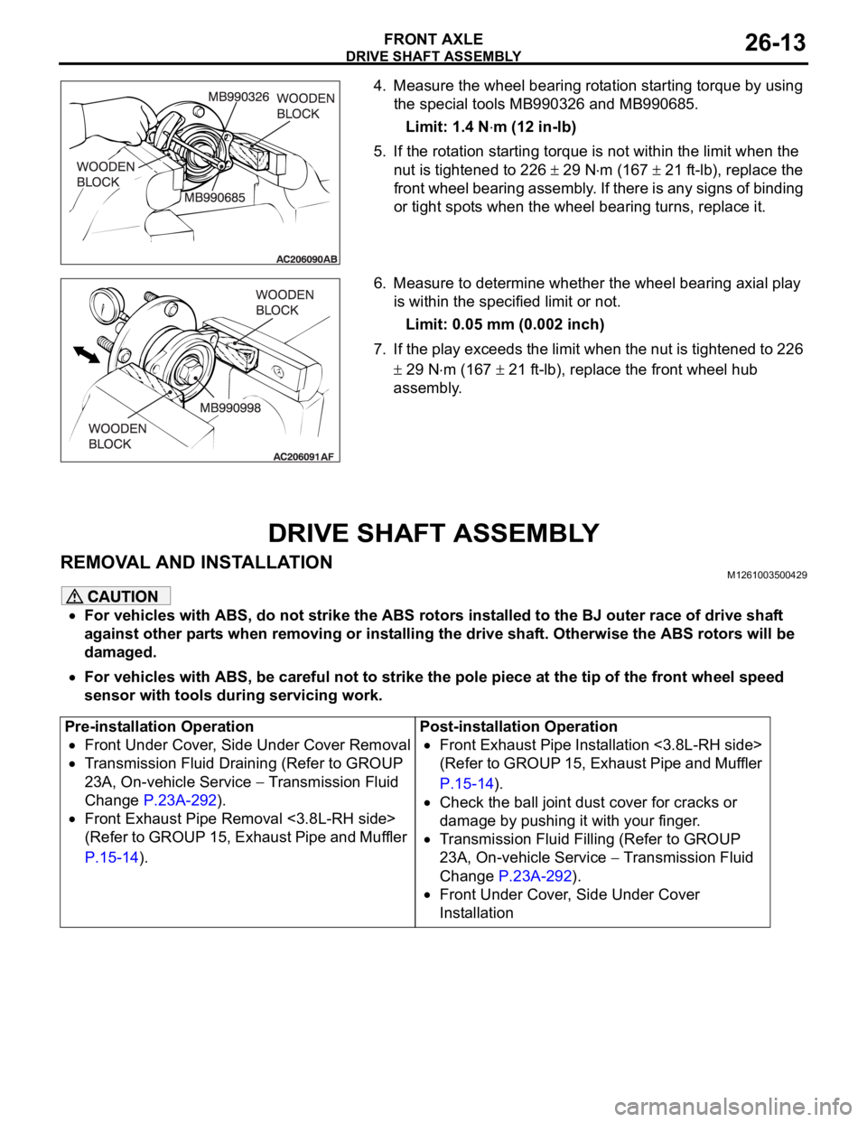
4. Measure the wheel bearing rotation starting torque by using
the special tools MB990326 and MB990685.
Limit: 1.4 N
m (12 in-lb)
5. If the rotation starting torque is not within the limit when the
nut is tightened to 226
29 Nm (167 21 ft-lb), replace the
front wheel bearing assembly. If there is any signs of binding
or tight spots when the wheel bearing turns, replace it.
6. Measure to determine whether the wheel bearing axial play
is within the specified limit or not.
Limit: 0.05 mm (0.002 inch)
7. If the play exceeds the limit when the nut is tightened to 226
29 Nm (167 21 ft-lb), replace the front wheel hub
assembly.
DRIVE SHAFT ASSEMBLY
REMOVAL AND INSTALLATIONM1261003500429
For vehicles with ABS, do not strike the ABS rotors installed to the BJ outer race of drive shaft
against other parts when removing or installing the drive shaft. Otherwise the ABS rotors will be
damaged.
For vehicles with ABS, be careful not to strike the pole piece at the tip of the front wheel speed
sensor with tools during servicing work.
Pre-installation Operation
Front Under Cover, Side Under Cover Removal
Transmission Fluid Draining (Refer to GROUP
23A, On-vehicle Service
Transmission Fluid
Change P.23A-292).
Front Exhaust Pipe Removal <3.8L-RH side>
(Refer to GROUP 15, Exhaust Pipe and Muffler
P.15-14).Post-installation Operation
Front Exhaust Pipe Installation <3.8L-RH side>
(Refer to GROUP 15, Exhaust Pipe and Muffler
P.15-14).
Check the ball joint dust cover for cracks or
damage by pushing it with your finger.
Transmission Fluid Filling (Refer to GROUP
23A, On-vehicle Service
Transmission Fluid
Change P.23A-292).
Front Under Cover, Side Under Cover
Installation
Page 1431 of 1500
Page 1453 of 1500
Page 1461 of 1500

AUTOMATIC TRANSMISSION23A-2
SPECIAL TOOLS . . . . . . . . . . . . . . . .23A-286
ON-VEHICLE SERVICE. . . . . . . . . . .23A-289
A/T CONTROL COMPONENT LAYOUT . . 23A-289
ESSENTIAL SERVICE . . . . . . . . . . . . . . . . 23A-291
TRANSMISSION FLUID CHECK . . . . . . . . 23A-291
TRANSMISSION FLUID CHANGE . . . . . . . 23A-292
OIL COOLER FLOW CHECK . . . . . . . . . . . 23A-294
TRANSMISSION RANGE SWITCH
CHECK . . . . . . . . . . . . . . . . . . . . . . . . . . . . 23A-294
TRANSMISSION RANGE SWITCH AND
CONTROL CABLE ADJUSTMENT. . . . . . . 23A-294
AUTOMATIC TRANSMISSION CONTROL
COMPONENT CHECK . . . . . . . . . . . . . . . . 23A-295
CRANKSHAFT POSITION SENSOR
CHECK . . . . . . . . . . . . . . . . . . . . . . . . . . . . 23A-295
TRANSMISSION FLUID TEMPERATURE
SENSOR CHECK . . . . . . . . . . . . . . . . . . . . 23A-296
TRANSMISSION RANGE SWITCH
CHECK . . . . . . . . . . . . . . . . . . . . . . . . . . . . 23A-296
STOPLIGHT SWITCH CHECK . . . . . . . . . . 23A-296
A/T CONTROL RELAY CHECK . . . . . . . . . 23A-296
SOLENOID VALVE CHECK . . . . . . . . . . . . 23A-298SELECTOR LEVER OPERATION
CHECK . . . . . . . . . . . . . . . . . . . . . . . . . . . . 23A-299
TRANSMISSION CONTROL CABLE
ADJUSTMENT . . . . . . . . . . . . . . . . . . . . . . 23A-299
TRANSMISSION CONTROL* . . . . . . .23A-300
REMOVAL AND INSTALLATION . . . . . . . . 23A-300
INSPECTION. . . . . . . . . . . . . . . . . . . . . . . . 23A-301
DISASSEMBLY AND ASSEMBLY . . . . . . . 23A-302
INSPECTION. . . . . . . . . . . . . . . . . . . . . . . . 23A-303
TRANSMISSION ASSEMBLY . . . . . .23A-304
REMOVAL AND INSTALLATION . . . . . . . . 23A-304
TRANSMISSION FLUID COOLER,
HOSE AND PIPE . . . . . . . . . . . . . . . .23A-312
REMOVAL AND INSTALLATION . . . . . . . . 23A-312
SPECIFICATIONS . . . . . . . . . . . . . . .23A-313
FASTENER TIGHTENING
SPECIFICATIONS. . . . . . . . . . . . . . . . . . . . 23A-313
SERVICE SPECIFICATIONS . . . . . . . . . . . 23A-313
LUBRICANT . . . . . . . . . . . . . . . . . . . . . . . . 23A-314
Page 1471 of 1500
AUTOMATIC TRANSMISSION DIAGNOSIS
AUTOMATIC TRANSMISSION23A-12
AUTOMATIC TRANSMISSION DIAGNOSIS
DIAGNOSTIC TROUBLESHOOTING FLOWM1231013500353
INTRODUCTION TO A/T DIAGNOSISM1231012300226
The automatic transmission can exhibit any of the
following symptoms: noise or vibration is generated,
Transmission fluid leaks, the vehicle does not move
forward or backward. The causes of these symptoms
could come from: Incorrect mounting, the Transmis-
sion fluid may be low, or a component of the
transmission may be faulty. The following items are suspected as causes for the
INVECS-II troubles: malfunction of the A/T-ECU, the
sensors, the switches, the harness or connectors.