Page 1341 of 1500

AUTO-CRUISE CONTROL
ENGINE AND EMISSION CONTROL17-10
AUTO-CRUISE CONTROL
GENERAL DESCRIPTIONM1172000100281
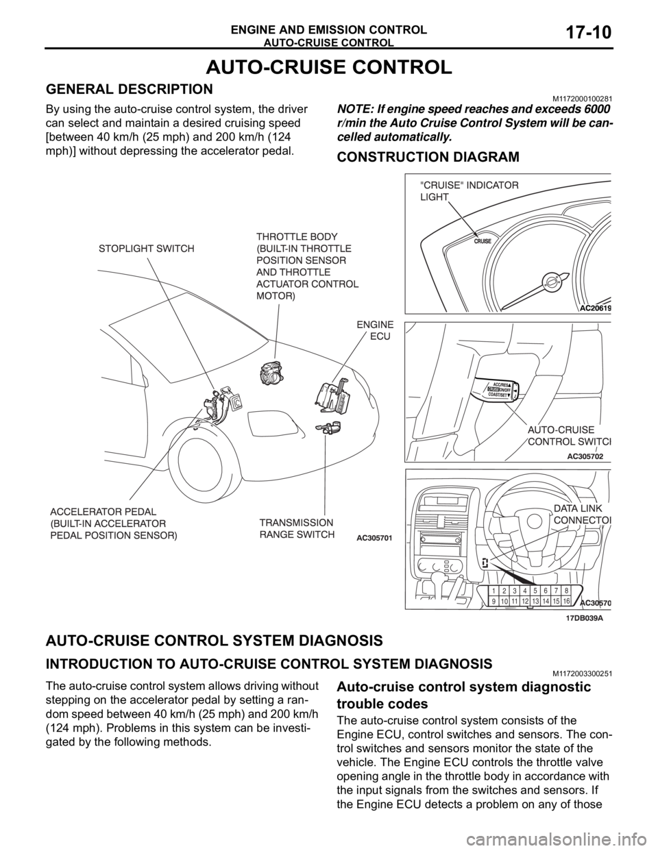
By using the auto-cruise control system, the driver
can select and maintain a desired cruising speed
[between 40 km/h (25 mph) and 200 km/h (124
mph)] without depressing the accelerator pedal.NOTE: If engine speed reaches and exceeds 6000
r/min the Auto Cruise Control System will be can-
celled automatically.
CONSTRUCTION DIAGRAM
AUTO-CRUISE CONTROL SYSTEM DIAGNOSIS
INTRODUCTION TO AUTO-CRUISE CONTROL SYSTEM DIAGNOSISM1172003300251
The auto-cruise control system allows driving without
stepping on the accelerator pedal by setting a ran-
dom speed between 40 km/h (25 mph) and 200 km/h
(124 mph). Problems in this system can be investi-
gated by the following methods.Auto-cruise control system diagnostic
trouble codes
The auto-cruise control system consists of the
Engine ECU, control switches and sensors. The con-
trol switches and sensors monitor the state of the
vehicle. The Engine ECU controls the throttle valve
opening angle in the throttle body in accordance with
the input signals from the switches and sensors. If
the Engine ECU detects a problem on any of those
91
01
1
12
1
31
41
5
16 123
456
78
Page 1391 of 1500

AUTO-CRUISE CONTROL
ENGINE AND EMISSION CONTROL17-60
INSPECTION PROCEDURE 6: Hunting (Repeated Acceleration and Deceleration) Occurs at the Set
Vehicle Speed.
.
COMMENT
The output shaft speed sensor signal or the throttle
body is suspected.
.
TROUBLESHOOTING HINTS (THE MOST
LIKELY CAUSES FOR THIS CASE:)
Malfunction of the output shaft speed sensor.
Malfunction of the throttle body.
Malfunction of the Engine ECU.
Malfunction of the A/T ECU.
Circuit drawings
Refer to circuit diagrams GROUP-90
Refer to configuration diagrams GROUP-80
Refer to component locations GROUP-70
DIAGNOSIS
Required Special Tools:
MB991958: Diagnostic Tool (MUT-III Sub Assembly)
MB991824: V.C.I.
MB991827: MUT-III USB Cable
MB991910: MUT-III Main Harness A
STEP 1. Using Diagnostic Tool MB991958, read the
diagnostic trouble code.
To prevent damage to Diagnostic Tool MB991958, always
turn the ignition switch to the "LOCK" (OFF) position
before connecting or disconnecting Diagnostic Tool
MB991958.
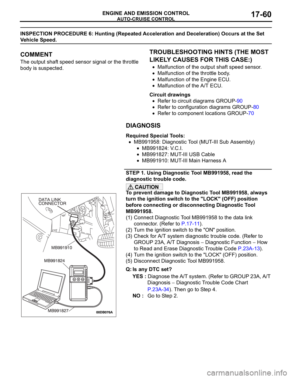
(1) Connect Diagnostic Tool MB991958 to the data link
connector. (Refer to P.17-11).
(2) Turn the ignition switch to the "ON" position.
(3) Check for A/T system diagnostic trouble code. (Refer to
GROUP 23A, A/T Diagnosis
Diagnostic Function How
to Read and Erase Diagnostic Trouble Code P.23A-13).
(4) Turn the ignition switch to the "LOCK" (OFF) position.
(5) Disconnect Diagnostic Tool MB991958.
Q: Is any DTC set?
YES : Diagnose the A/T system. (Refer to GROUP 23A, A/T
Diagnosis
Diagnostic Trouble Code Chart
P.23A-34). Then go to Step 4.
NO : Go to Step 2.
Page 1396 of 1500

AUTO-CRUISE CONTROL
ENGINE AND EMISSION CONTROL17-65
DATA LIST REFERENCE TABLE - Auto Cruise ControlM1172002400471
When shifting the selector lever to "D" range, apply the brakes so that the vehicle does not move
forward.
Driving tests always need two persons: one driver and one observer.
NOTE: *:After the inspection is completed, disconnect the throttle position sensor connector, and then delete
the diagnostic trouble code using use of Diagnostic Tool MB991958. (Refer to P.17-11).
MUT-III
Diagnostic
To o l
DISPLAYITEM
NO.INSPECTION ITEM INSPECTION REQUIREMENT NORMAL
CONDITION
APS
SNS(MAIN)11 A c c e l e r a t o r p e d a l
position sensor (main)Ignition
switch:
"ON"Accelerator pedal: Released
435
1,035 mV
Accelerator pedal: Gradually
depressedIncreases in
response to the
pedal depression
stroke
Accelerator pedal: Fully
depressed4,000 mV or more
BRAKE SW 89 Stoplamp switch Brake pedal: Depressed ON
Brake pedal: Released OFF
CANCEL
CODE57 Cancel code Ignition switch: "ON" The cancel code,
which set when the
auto-cruise control
system was
cancelled at the
last time, is set
again.
CANCEL
SWITCH75 Auto-cruise
control
switchCANCEL "CANCEL" switch: ON ON
"CANCEL" switch: OFF OFF
CLUTCH SW 78 Transmission inhibitor
switchTransmission inhibitor switch: "P" or
"N"ON
Transmission inhibitor switch: Other
than aboveOFF
CRUISE 81 Auto-cruise control
system operationAuto-cruise control system: active ON
Auto-cruise control system: Inactive OFF
MAIN SW 86 Auto-cruise
control
switchCRUISE
(MAIN)"CRUISE" (MAIN) switch: "ON" ON
"CRUISE" (MAIN) switch: "OFF" OFF
RESUME
SWITCH91 Auto-cruise
control
switchACC/RES "ACC/RES" switch: ON ON
"ACC/RES" switch: OFF OFF
SET SWITCH 92 Auto-cruise
control
switchCOAST/S
ET"COAST/SET" switch: ON ON
"COAST/SET" switch: OFF OFF
STOPLIGHT
SW74 Stoplamp switch Brake pedal: Depressed ON
Brake pedal: Released OFF
Page 1397 of 1500

AUTO-CRUISE CONTROL
ENGINE AND EMISSION CONTROL17-66
If the air intake duct is removed from the throttle body take great care to keep fingers away
from the throttle plate. The drive motor has very high torque and is capable of random move-
ment at any time. Do not under any circumstances activate the throttle plate by hand.
When removing the throttle body from the intake manifold disconnect the wiring first. During
replacement connect the wiring last.
Do not activate the throttle body using a DC suppy to test the motor,as permanent damage to
the throttle body will result.
TP
SNSR(MAIN)13 Throttle position sensor
(main)*(1) Accelerator pedal:
Released
(2) Accelerator pedal:
Depressed(1) Throttle
valve fully
closed1035 1250 mV
(2) Throttle
valve fully
open4,000 mV or more
A/C switch: "OFF" to "ON" Voltage rises
Selector lever: "N" to "D" Voltage rises
VSS 04 Vehicle speed signal Road test the vehicle The speedometer
and Diagnostic
Tool MB991958
display the same
value. MUT-III
Diagnostic
To o l
DISPLAYITEM
NO.INSPECTION ITEM INSPECTION REQUIREMENT NORMAL
CONDITION
Page 1398 of 1500

AUTO-CRUISE CONTROL
ENGINE AND EMISSION CONTROL17-67
ENGINE ECU TERMINAL VOLTAGE REFERENCE CHART FOR AUTO-CRUISE
CONTROL SYSTEM OPERATION
M1172004800055
1. Disconnect the Engine ECU connectors B-20,
B-21, and connect special tool MB992044
(ENGINE ECU check harness) in between.2. Measure the voltages between the check
connector terminals of special tool MB992044 and
ground connector B-21 terminals 4 or 6.
TERMINAL
NO.CHECK ITEM CHECK CONDITION NORMAL
CONDITION
18 (B-21) Stoplamp switch Ignition
switch:
"ON"Depress the brake pedal. Battery positive
voltage
Release the brake pedal. 1V or less
14 (B-21) Auto-cruise control
switch power supplyIgnition
switch:
"ON"All switches: OFF 4.7
5.0 V
"CRUISE" (MAIN) switch: "ON" 0
0.3 V
"COAST/SET" switch: ON 2.0
2.8 V
"ACC/RES" switch: ON 3.3
4.1 V
"CANCEL" switch: ON 0.8
1.5 V
76 (B-21) Accelerator pedal
position sensor (sub)
power supplyIgnition switch: "ON" 4.9
5.1 V
59 (B-21) Accelerator pedal
position sensor
(main)Ignition
switch:
"ON"Release the accelerator pedal
0.435
1.035 V
Depress the accelerator pedal. 4.0 V or more
81 (B-21) Accelerator pedal
position sensor (sub)Ignition
switch:
"ON"Release the accelerator pedal
0.435
1.035 V
Depress the accelerator pedal. 4.0 V or more
75 (B-21) Accelerator pedal
position sensor
(main) power supplyIgnition switch: "ON" 4.9
5.1 V
21 (B-21) Brake switch Ignition
switch:
"ON"Depress the brake pedal. 1V or less
Release the brake pedal. 1V or less
9 (B-20) Transmission inhibitor
switch: "P" and "N"
Crank switch signalIgnition
switch:
"ON"Transmission inhibitor switch: "P" or
"N" Crank switch signalBattery positive
voltage
Transmission inhibitor switch: Other
than above1V or less
Page 1399 of 1500

AUTO-CRUISE CONTROL
ENGINE AND EMISSION CONTROL17-68
If the air intake duct is removed from the throttle body take great care to keep fingers away
from the throttle plate. The drive motor has very high torque and is capable of random move-
ment at any time. Do not under any circumstances activate the throttle plate by hand.
When removing the throttle body from the intake manifold disconnect the wiring first. During
replacement connect the wiring last.
Do not activate the throttle body using a DC suppy to test the motor,as permanent damage to
the throttle body will result.
10 (B-20) Throttle position
sensor power supplyIgnition switch: "ON" 4.9 5.1 V
57 (B-20) Throttle position
sensor (sub)(1) Accelerator pedal:
Released
(2) Accelerator pedal:
Depressed(1) Throttle
valve fully
closed1035
1250 mV
(2) Throttle
valve fully open4000 mV or more
42 (B-20) Throttle position
sensor (main)(1) Accelerator pedal:
Released
(2) Accelerator pedal:
Depressed(1) Throttle
valve fully
closed1035
1250 mV
(2) Throttle
valve fully open4000 mV or more
49 (B-20) Throttle actuator
control motor (
)
Ignition switch: "ON"
Accelerator pedal: fully closed to fully
openedDecreases slightly
(approx. 2 V) from
battery voltage.
50 (B-20) Throttle actuator
control motor (+)
Ignition switch: "ON"
Accelerator pedal: fully opened to fully
closedDecreases slightly
(approx. 2 V) from
battery voltage. TERMINAL
NO.CHECK ITEM CHECK CONDITION NORMAL
CONDITION
Page 1405 of 1500
AUTO-CRUISE CONTROL
ENGINE AND EMISSION CONTROL17-74
THROTTLE POSITION SENSOR
Refer to GROUP 13A, On-vehicle Service Throttle Actuator
Control Motor Check 13A-671 (3.8L engine).
If the air intake duct is removed from the throttle
body take great care to keep fingers away from the
throttle plate. The drive motor has very high torque
and is capable of random movement at any time. Do
not under any circumstance activate the throttle plate
by hand.
When removing the throttle body from the intake
manifold disconnect the wiring first.During replace-
ment connect the wiring last.
Do not activate the throttle body using a DC supply to
test the motor, as permanent damage to the throttle
body will result.
TRANSMISSION INHIBITOR SWITCH ("N"
POSITION)
Refer to GROUP 23A, On-vehicle Service Essential Service
P.23A-294.
Page 1406 of 1500
AUTO-CRUISE CONTROL
ENGINE AND EMISSION CONTROL17-75
AUTO-CRUISE CONTROL
REMOVAL AND INSTALLATIONM1172001400467
Before removal of the air bag module, refer to GROUP 52B, SRS Service Precautions
P.52B-16 and GROUP 52B, Air Bag Module and Clock Spring P.52B-237.
CONTROL SWITCH REMOVAL
STEPS
1. AIR BAG MODULE
SIDE> (REFER TO GROUP 52B, AIR
BAG MODULES AND CLOCK
SPRING P.52B-237)
2. STEERING WHEEL ASSEMBLY
(REFER TO GROUP 37, STEERING
WHEEL P.37-23)
3. LOWER COVER CAP
4. AUTO-CRUISE CONTROL SWITCH
CONTROL UNIT REMOVAL
5. Engine ECU [REFER TO GROUP
13A, Engine ECU 13A-675] SENSOR REMOVAL STEPS
6. TRANSMISSION INHIBITOR
SWITCH (REFER TO GROUP 23B,
AUTOMATIC TRANSMISSION)
7. THROTTLE BODY (BUILT-IN
THROTTLE POSITION SENSOR
AND THROTTLE ACTUATOR
CONTROL MOTOR) (REFER TO
GROUP 13A, THROTTLE BODY
13A-660)
8. ACCELERATOR PEDAL (BUILT-IN
ACCELERATOR PEDAL POSITION
SENSOR) (REFER TO GROUP 17,
ACCELERATOR PEDAL P.17-9)
9. STOPLIGHT SWITCH (REFER TO
GROUP 35A, BRAKE PEDAL
P.35A-24)