2005 MITSUBISHI 380 stop light
[x] Cancel search: stop lightPage 5 of 1500

GENERAL DESCRIPTION
SIMPLIFIED WIRING SYSTEM (SWS)54B-5
INTERMITTENT CONTROL
ETACS-ECU uses the dial position of the variable
intermittent wiper control switch and the vehicle
speed signal sent by the combination meter to calcu-
late the interval to be sent to the front-ECU. The
front-ECU determines the intermittent time from the
input SWS data signal, and turns ON the windshield
wiper drive signal. When the wiper is at the STOP
position, the windshield wiper auto-stop signal goes
OFF to turn OFF the windshield wiper drive signal.
After the intermittent time from when the windshield
wiper drive signal turned ON, the windshield wiper
drive signal is turned ON again and the above opera-
tion is repeated.
.
MIST WIPER CONTROL
When the ignition switch is in the ACC or ON posi-
tion, and the windshield mist wiper switch of the col-
umn switch is turned ON, the front-ECU turns ON the
windshield wiper drive signal. At the same time, the
wiper speed switching relay is turned ON
(HIGH-SPEED). While the windshield mist wiper
switch is ON, the windshield wiper will operate at
high speed. Then, if the windshield mist wiper switch
is turned off, the wiper operates at low speed until it
stops at the predetermined park position.
When the windshield mist switch is turned on briefly,
the wiper operates once at low speed.
At the point the windshield mist switch is turned ON,
if the windshield wiper has been operating intermit-
tently, the same operations as the above will be per-
formed while the windshield mist wiper switch is ON.
After the windshield mist wiper switch goes OFF, the
intermittent operations will be set again after the
windshield wiper auto-stop signal last is turned ON.
.
WASHER CONTROL
When the ignition switch is in the ACC or ON posi-
tion, and the windshield washer switch of the column
switch is turned ON, the front-ECU turns ON the
windshield washer relay. The windshield wiper drive
signal is turned ON in 0.15 seconds until 2 seconds
after the windshield washer switch goes OFF to
operate the windshield wiper continuously. When the
windshield washer switch is turned ON, if the wind-
shield wiper is operating intermittently, intermittent
operations will be continued after continuous opera-
tions.
HEADLAMP
.
HEADLAMP AUTOMATIC SHUTDOWN
FUNCTION
Even if the lighting switch (tail lamp switch or
headlamp switch) is ON, the headlamps and tail
lamps will automatically go off in the following condi-
tions to prevent the battery from discharging:
When the ignition key is turned from "ON" to "LOCK"
(OFF) or "ACC" position with the lighting switch
turned ON, and this state continues for three min-
utes, the lamp will automatically be turned off. If the
driver's seat door is opened during these three min-
utes, the lamp will go off one second later.
.
HIGH-BEAM INDICATOR
At the same time that the high beams are illumi-
nated, the ETACS-ECU sends a signal to illuminate
the high-beam indicator via the CAN bus line. The
combination meter receives the transmitted signal
and turns the high-beam indicator on and off.
FLASHER TIMER
.
TURN-SIGNAL LAMP
The turn-signal lamp output (flashing signal) is
turned ON when the ignition switch is ON and the
turn-signal lamp switch is ON (LH or RH). If the front
turn-signal lamp or rear turn-signal lamp bulb has
burned out, the flashing speed increases to indicate
that the bulb has burned out.
.
HAZARD WARNING LAMP
Detects the signal where the hazard warning lamp
switch input changes from OFF to ON, and reverse
the flashing state according to this signal. The haz-
ard warning lamps toggle on and off whenever the
hazard warning lamp switch is operated.
.
TURN-SIGNAL INDICATORS
At the same time that the turn-signal lamps are illu-
minated, the ETACS-ECU sends a signal to illumi-
nate the turn-signal lamp indicator via the CAN bus
line. The combination meter receives the transmitted
signal and turns the turn-signal lamp indicator on and
off.
Page 484 of 1500

CHECK AT ECU TERMINAL
SIMPLIFIED WIRING SYSTEM (SWS)54B-484
FRONT-ECU
NOTE: Terminal voltages cannot be measured as the
front-ECU is installed directly on the relay box.
Therefore, this information is only for reference.
TERMINAL
NO.INSPECTION ITEM INSPECTION CONDITION NORMAL VALUE
1 Output to fog lamp relay When the fog lamps are on Battery positive voltage
2 Output to headlamp (high-beam) When headlights (high-beam)
are onBattery positive voltage
3, 4 Battery power supply (for
headlamp)Always Battery positive voltage
5 Battery power supply (for
taillamp)Always Battery positive voltage
6 Output to headlamp (low-beam) When headlights (low-beam) are
onBattery positive voltage
7 Battery power supply (for ECU) Always Battery positive voltage
8 Output to taillamps When taillamps are on Battery positive voltage
9
11
21 Output to windshield washer When windshield washer is on Battery positive voltage
22 SWS communication line Always 0
12 V (pulse signal)
23 Input of automatic stop signal to
windshield wiperWhen windshield wiper is on Battery positive voltage
24 Power supply to ignition switch
(ACC)Ignition switch: "ACC" Battery positive voltage
25 Input of backup signal from
headlamp switchHeadlamp switch: ON0 V
26 Input of backup signal to
windshield wiperWindshield low-speed wiper
switch or windshield high-speed
wiper switch: ON0 V
27 Output to windshield wiper
(low-speed)When windshield wiper is on (at
low speed)Battery positive voltage
28 Output to windshield wiper
(high-speed)When windshield wiper is on (at
high speed)Battery positive voltage
30 Power supply to ignition switch
(IG2)Ignition switch: "ON" Battery positive voltage
31 Ground Always 0 V
Page 573 of 1500

LUGGAGE COMPARTMENT
CONFIGURATION DIAGRAMS80-24
LUGGAGE COMPARTMENTM1801001500311
F-01 (2-GR) HIGH-MOUNTED STOPLIGHT
F-02 (2) HIGH-MOUNTED STOPLIGHT
F-03 (6) REAR COMBINATION LIGHT (RH)F-05 (2) TRUNK LID LATCH ACTUATOR
ASSEMBLY
F-06 (2) LICENSE PLATE LIGHTS
F-09 (6) REAR COMBINATION LIGHT (LH)
F-10 (2) FUEL DOOR LID ACTUATOR
Page 853 of 1500

HEATER UNIT, HEATER CORE, BLOWER ASSEMBLY AND EVAPORATOR UNIT
HEATER, AIR CONDITIONING AND VENTILATION55-152
REMOVAL SERVICE POINTS
.
<> SUCTION PIPE AND LIQUID PIPE DISCON-
NECTION
As the compressor oil and receiver are highly moisture
absorbent, use a non-porous material to plug the hose and
nipples.
To prevent the entry of dust or other foreign bodies, plug the
dismantled hose and the nipples of the expansion valves.
.
<> HEATER UNIT AND DECK
CROSSMEMBER ASSEMBLY REMOVAL
Disconnect the following connectors to gain access to the front
deck crossmember.
6. ETACS-ECU
<>7. HEATER UNIT AND DECK
CROSSMEMBER ASSEMBLY REMOVAL STEPS (Continued)
Connector
numberConnector name
C-113 AUDIO AMPLIFIER
C-114 AUDIO AMPLIFIER
C-25 FRONT WIRING HARNESS AND FLOOR
WIRING HARNESS COMBINATION
C-26 INSTRUMENT PANEL WIRING HARNESS
AND FRONT DOOR WIRING HARNESS (LH)
COMBINATION
C-27 INSTRUMENT PANEL WIRING HARNESS
AND ROOF WIRING HARNESS
COMBINATION
C-28 INSTRUMENT PANEL WIRING HARNESS
AND FLOOR WIRING HARNESS
COMBINATION
C-29 INSTRUMENT PANEL WIRING HARNESS
AND FRONT WIRING HARNESS
COMBINATION
C-30 STOPLIGHT SWITCH
C-07 CLUTCH PEDAL SWITCH
Page 1044 of 1500

REAR SPOILER
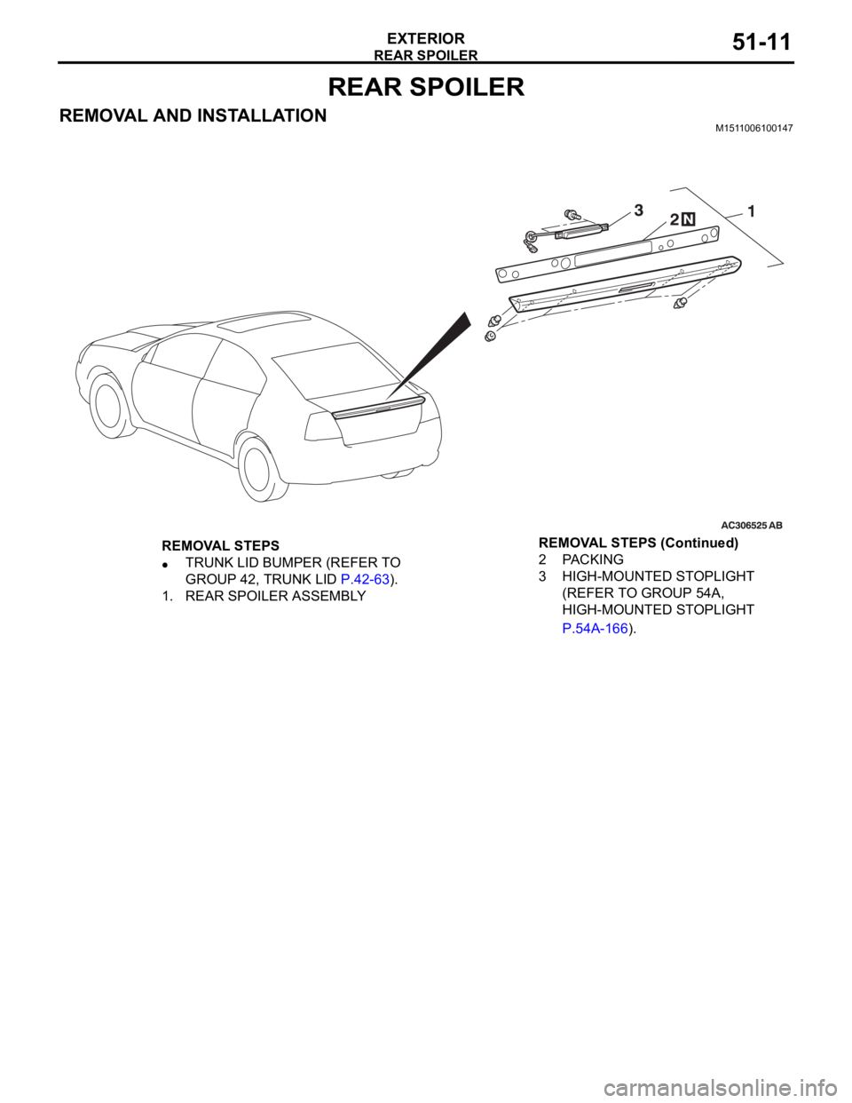
EXTERIOR51-11
REAR SPOILER
REMOVAL AND INSTALLATIONM1511006100147
REMOVAL STEPS
TRUNK LID BUMPER (REFER TO
GROUP 42, TRUNK LID P.42-63).
1. REAR SPOILER ASSEMBLY2PACKING
3 HIGH-MOUNTED STOPLIGHT
(REFER TO GROUP 54A,
HIGH-MOUNTED STOPLIGHT
P.54A-166). REMOVAL STEPS (Continued)
Page 1131 of 1500

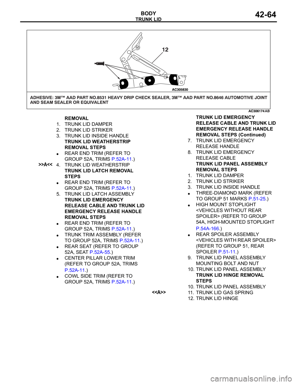
TRUNK LID
BODY42-64
REMOVAL
1. TRUNK LID DAMPER
2. TRUNK LID STRIKER
3. TRUNK LID INSIDE HANDLE
TRUNK LID WEATHERSTRIP
REMOVAL STEPS
REAR END TRIM (REFER TO
GROUP 52A, TRIMS P.52A-11.)
>>A<<4. TRUNK LID WEATHERSTRIP
TRUNK LID LATCH REMOVAL
STEPS
REAR END TRIM (REFER TO
GROUP 52A, TRIMS P.52A-11.)
5. TRUNK LID LATCH ASSEMBLY
TRUNK LID EMERGENCY
RELEASE CABLE AND TRUNK LID
EMERGENCY RELEASE HANDLE
REMOVAL STEPS
REAR END TRIM (REFER TO
GROUP 52A, TRIMS P.52A-11.)
TRUNK TRIM ASSEMBLY (REFER
TO GROUP 52A, TRIMS P.52A-11.)
REAR SEAT (REFER TO GROUP
52A, SEAT P.52A-55.)
CENTER PILLAR LOWER TRIM
(REFER TO GROUP 52A, TRIMS
P.52A-11.)
COWL SIDE TRIM (REFER TO
GROUP 52A, TRIMS P.52A-11.)7. TRUNK LID EMERGENCY
RELEASE HANDLE
8. TRUNK LID EMERGENCY
RELEASE CABLE
TRUNK LID PANEL ASSEMBLY
REMOVAL STEPS
1. TRUNK LID DAMPER
2. TRUNK LID STRIKER
3. TRUNK LID INSIDE HANDLE
THREE-DIAMOND MARK (REFER
TO GROUP 51 MARKS P.51-25.)
HIGH MOUNT STOPLIGHT
54A, HIGH-MOUNTED STOPLIGHT
P.54A-166.)
REAR SPOILER ASSEMBLY
(REFER TO GROUP 51, REAR
SPOILER P.51-11.)
9. TRUNK LID PANEL ASSEMBLY
MOUNTING BOLT AND NUT
10. TRUNK LID PANEL ASSEMBLY
TRUNK LID HINGE REMOVAL
STEPS
10. TRUNK LID PANEL ASSEMBLY
<>11. TRUNK LID GAS SPRING
12. TRUNK LID HINGETRUNK LID EMERGENCY
RELEASE CABLE AND TRUNK LID
EMERGENCY RELEASE HANDLE
REMOVAL STEPS (Continued)
Page 1178 of 1500

ON-VEHICLE SERVICE
BASIC BRAKE SYSTEM35A-13
ON-VEHICLE SERVICE
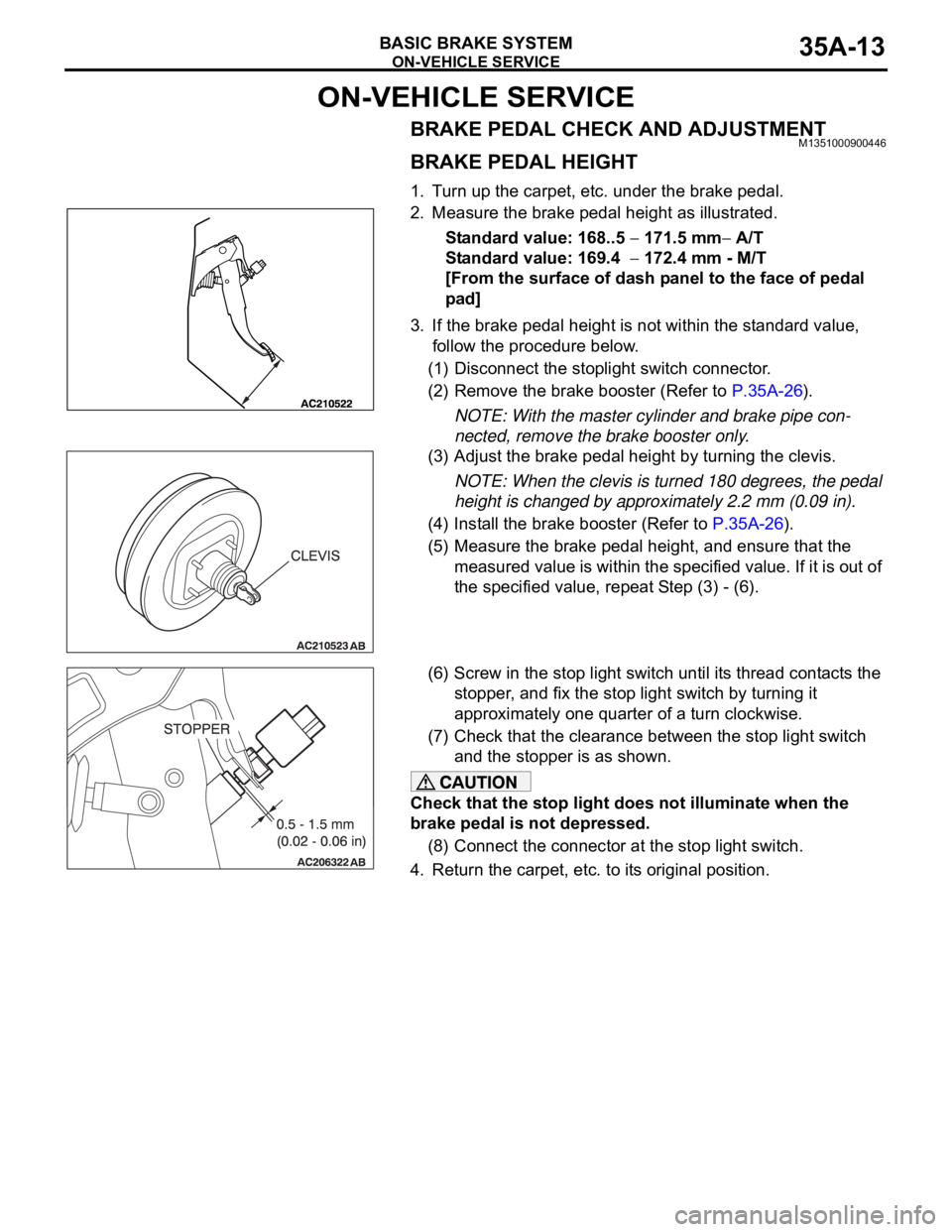
BRAKE PEDAL CHECK AND ADJUSTMENTM1351000900446
BRAKE PEDAL HEIGHT
1. Turn up the carpet, etc. under the brake pedal.
2. Measure the brake pedal height as illustrated.
Standard value: 168..5
171.5 mm A/T
Standard value: 169.4
172.4 mm - M/T
[From the surface of dash panel to the face of pedal
pad]
3. If the brake pedal height is not within the standard value,
follow the procedure below.
(1) Disconnect the stoplight switch connector.
(2) Remove the brake booster (Refer to P.35A-26).
NOTE: With the master cylinder and brake pipe con-
nected, remove the brake booster only.
(3) Adjust the brake pedal height by turning the clevis.
NOTE: When the clevis is turned 180 degrees, the pedal
height is changed by approximately 2.2 mm (0.09 in).
(4) Install the brake booster (Refer to P.35A-26).
(5) Measure the brake pedal height, and ensure that the
measured value is within the specified value. If it is out of
the specified value, repeat Step (3) - (6).
(6) Screw in the stop light switch until its thread contacts the
stopper, and fix the stop light switch by turning it
approximately one quarter of a turn clockwise.
(7) Check that the clearance between the stop light switch
and the stopper is as shown.
Check that the stop light does not illuminate when the
brake pedal is not depressed.
(8) Connect the connector at the stop light switch.
4. Return the carpet, etc. to its original position.
Page 1179 of 1500

ON-VEHICLE SERVICE
BASIC BRAKE SYSTEM35A-14
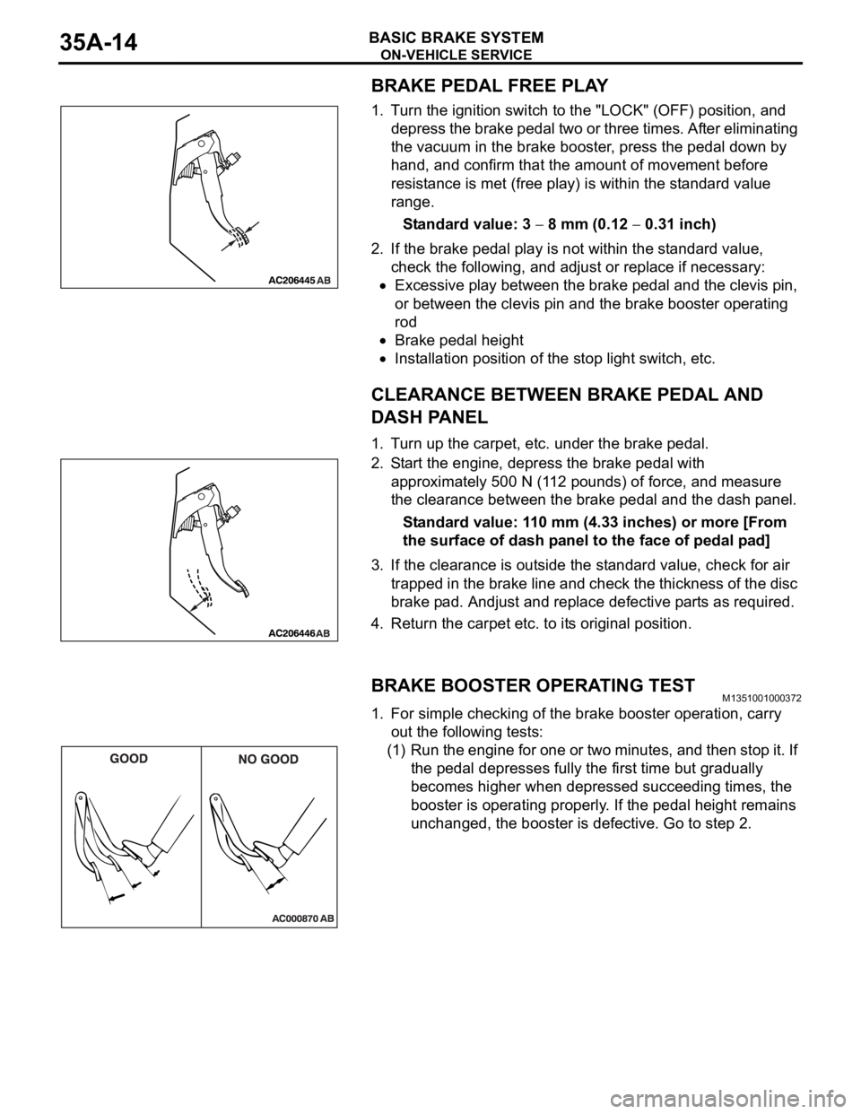
BRAKE PEDAL FREE PLAY
1. Turn the ignition switch to the "LOCK" (OFF) position, and
depress the brake pedal two or three times. After eliminating
the vacuum in the brake booster, press the pedal down by
hand, and confirm that the amount of movement before
resistance is met (free play) is within the standard value
range.
Standard value: 3
8 mm (0.12 0.31 inch)
2. If the brake pedal play is not within the standard value,
check the following, and adjust or replace if necessary:
Excessive play between the brake pedal and the clevis pin,
or between the clevis pin and the brake booster operating
rod
Brake pedal height
Installation position of the stop light switch, etc.
CLEARANCE BETWEEN BRAKE PEDAL AND
DASH PANEL
1. Turn up the carpet, etc. under the brake pedal.
2. Start the engine, depress the brake pedal with
approximately 500 N (112 pounds) of force, and measure
the clearance between the brake pedal and the dash panel.
Standard value: 110 mm (4.33 inches) or more [From
the surface of dash panel to the face of pedal pad]
3. If the clearance is outside the standard value, check for air
trapped in the brake line and check the thickness of the disc
brake pad. Andjust and replace defective parts as required.
4. Return the carpet etc. to its original position.
BRAKE BOOSTER OPERATING TESTM1351001000372
1. For simple checking of the brake booster operation, carry
out the following tests:
(1) Run the engine for one or two minutes, and then stop it. If
the pedal depresses fully the first time but gradually
becomes higher when depressed succeeding times, the
booster is operating properly. If the pedal height remains
unchanged, the booster is defective. Go to step 2.