Page 557 of 1500
ENGINE AND TRANSMISSION
CONFIGURATION DIAGRAMS80-8
B-101 (3-GR) IGNITION COIL 1
B-102 (3-GR) IGNITION COIL 3
B-103 (3-GR) IGNITION COIL 5
B-104 (2-B) ENGINE COOLANT TEMPERATURE
SENSOR
B-106 (3-B) CAMSHAFT POSITION SENSORB-107 (3-GR) OUTPUT SHAFT SPEED SENSOR
B-108 (10-GR) A/T CONTROL SOLENOID VALVE
ASSEMBLY
B-109 (3-B) INPUT SHAFT SPEED SENSOR
B-110 (10-B) TRANSMISSION INHIBITOR
(RANGE) SWITCH
Page 558 of 1500
ENGINE AND TRANSMISSION
CONFIGURATION DIAGRAMS80-9
B-112 (1) STARTER
B-113 (1-B) STARTER
B-114 (3-GR) IGNITION COIL 6
B-115 (1) ALTERNATOR
B-116 (2) ALTERNATORB-117 (3-GR) IGNITION COIL 4
B-118 (3-GR) IGNITION COIL 2
B-119 (3-B) CRANKSHAFT POSITION SENSOR
B-120 (2-GR) KNOCK SENSOR
Page 592 of 1500

CENTRALISED JUNCTION
CIRCUIT DIAGRAMS90-15
NO. POWER SUPPLY
CIRCUITNAME RATED
CAPACITY (A)HOUSING
COLOURLOAD CIRCUIT
1 Fusible link No.1 Fuse 30 Green Rear window demister
2 30 Green Blower motor and resistor
3
4
5 15 Blue Accessory socket
6 15 Blue Data link connector and ETACS-ECU
7 Ignition switch (ACC) 15 Blue ETACS-ECU
8
9 Ignition switch (IG2) 7.5 Brown Sunroof assembly
10 Ignition switch (ACC) 7.5 Brown Remote controlled mirror
11
12
13 Ignition switch (IG1) 7.5 Brown Fuel pump relay and Engine ECU
14 Ignition switch (ACC) 20 Yellow Windscreen wiper
15 Fusible link No.1
(Fuse No.5 in junction
block)7.5 Brown Remote controlled mirror
16 Ignition switch (IG2) 7.5 Brown A/C compressor clutch relay,
A/C-ECU, blower relay, condenser
fan motor, fan control relay,
front-ECU, outside/inside air selection
damper control motor and rear
window defogger relay
17 Ignition switch (IG1)
18 7.5 Brown A/T control relay, input shaft speed
sensor, output shaft speed sensor,
Engine ECU, rear combination lamp
and SRS-ECU
19 7.5 Brown ABS-ECU, ABS/TCL-ECU, column
switch, combination meter,
ETACS-ECU, multi-center display unit
and SRS-ECU
20 10 Red Ignition coil
21
22
23 Fusible link No.5 20 Yellow Sunroof assembly
24
Page 814 of 1500
AUTO A/C DIAGNOSIS
HEATER, AIR CONDITIONING AND VENTILATION55-113
STEP 5.Measure the voltage at choke coil connector D-11.
(1) Disconnect connector D-11, and measure the voltage at the
harness side.
(2) Disconnect A/C-ECU connector C-15 and ground harness
side terminal No.27.
(3) Turn the ignition switch to the "ON" position.
(4) Measure the voltage between choke coil connector D-11
terminal No.1 and ground.
The measured value should be approximately 12 volts.
Q: Is the measured voltage approx. 12 volts?
YES : Go to Step 13.
NO : Go to Step 6.
Page 907 of 1500

HOW TO DIAGNOSE
GENERAL 00E-6
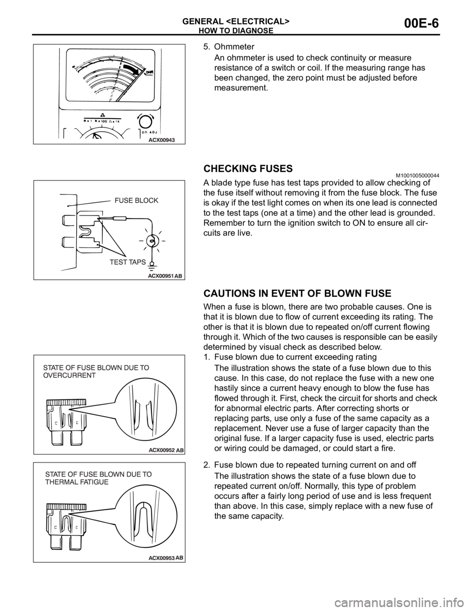
5. Ohmmeter
An ohmmeter is used to check continuity or measure
resistance of a switch or coil. If the measuring range has
been changed, the zero point must be adjusted before
measurement.
CHECKING FUSESM1001005000044
A blade type fuse has test taps provided to allow checking of
the fuse itself without removing it from the fuse block. The fuse
is okay if the test light comes on when its one lead is connected
to the test taps (one at a time) and the other lead is grounded.
Remember to turn the ignition switch to ON to ensure all cir-
cuits are live.
CAUTIONS IN EVENT OF BLOWN FUSE
When a fuse is blown, there are two probable causes. One is
that it is blown due to flow of current exceeding its rating. The
other is that it is blown due to repeated on/off current flowing
through it. Which of the two causes is responsible can be easily
determined by visual check as described below.
1. Fuse blown due to current exceeding rating
The illustration shows the state of a fuse blown due to this
cause. In this case, do not replace the fuse with a new one
hastily since a current heavy enough to blow the fuse has
flowed through it. First, check the circuit for shorts and check
for abnormal electric parts. After correcting shorts or
replacing parts, use only a fuse of the same capacity as a
replacement. Never use a fuse of larger capacity than the
original fuse. If a larger capacity fuse is used, electric parts
or wiring could be damaged, or could start a fire.
2. Fuse blown due to repeated turning current on and off
The illustration shows the state of a fuse blown due to
repeated current on/off. Normally, this type of problem
occurs after a fairly long period of use and is less frequent
than above. In this case, simply replace with a new fuse of
the same capacity.
Page 978 of 1500

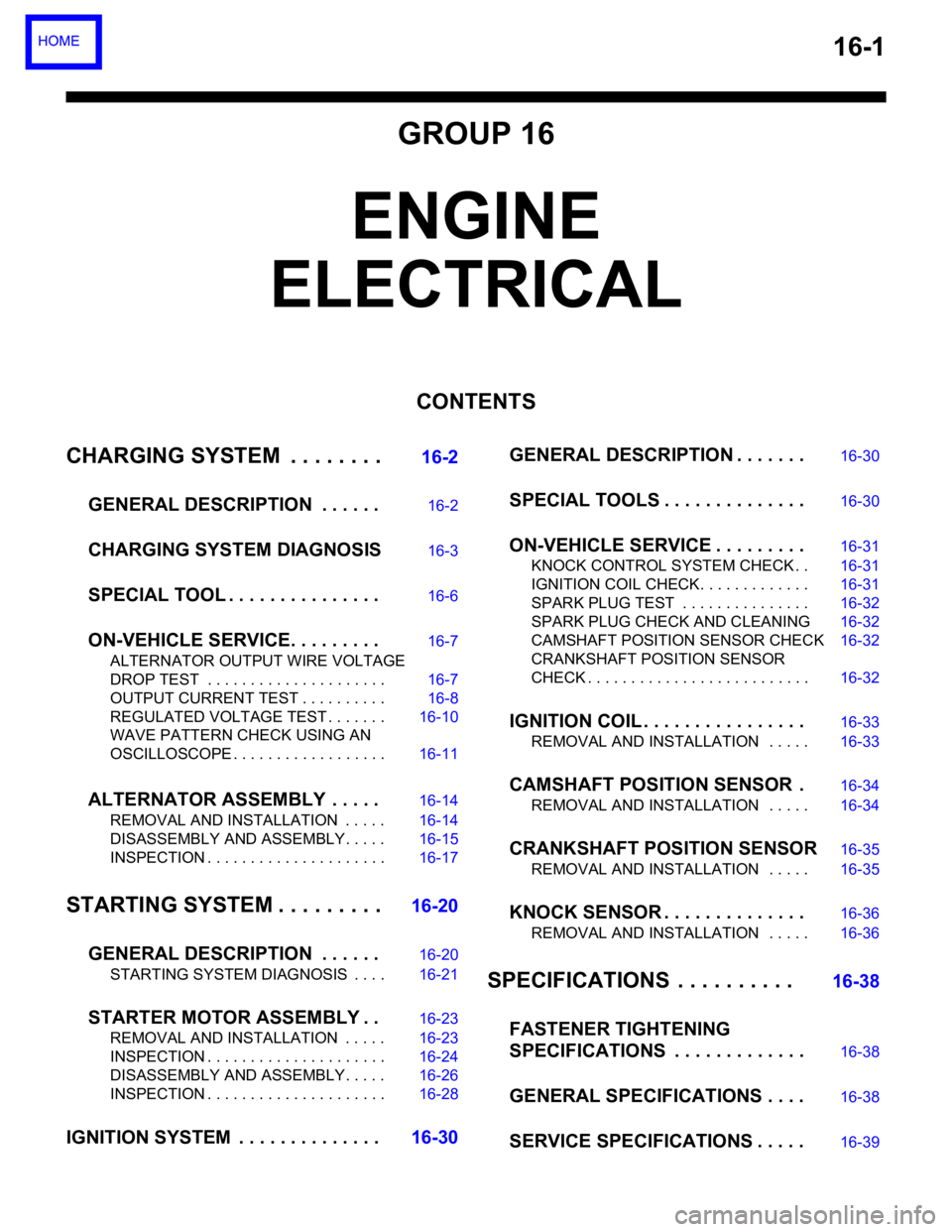
16-1
GROUP 16
ENGINE
ELECTRICAL
CONTENTS
CHARGING SYSTEM . . . . . . . .
16-2
GENERAL DESCRIPTION . . . . . .
16-2
CHARGING SYSTEM DIAGNOSIS16-3
SPECIAL TOOL . . . . . . . . . . . . . . .16-6
ON-VEHICLE SERVICE. . . . . . . . .16-7
ALTERNATOR OUTPUT WIRE VOLTAGE
DROP TEST . . . . . . . . . . . . . . . . . . . . . 16-7
OUTPUT CURRENT TEST . . . . . . . . . . 16-8
REGULATED VOLTAGE TEST . . . . . . . 16-10
WAVE PATTERN CHECK USING AN
OSCILLOSCOPE . . . . . . . . . . . . . . . . . . 16-11
ALTERNATOR ASSEMBLY . . . . .16-14
REMOVAL AND INSTALLATION . . . . . 16-14
DISASSEMBLY AND ASSEMBLY. . . . . 16-15
INSPECTION . . . . . . . . . . . . . . . . . . . . . 16-17
STARTING SYSTEM . . . . . . . . .16-20
GENERAL DESCRIPTION . . . . . .
16-20
STARTING SYSTEM DIAGNOSIS . . . . 16-21
STARTER MOTOR ASSEMBLY . .16-23
REMOVAL AND INSTALLATION . . . . . 16-23
INSPECTION . . . . . . . . . . . . . . . . . . . . . 16-24
DISASSEMBLY AND ASSEMBLY. . . . . 16-26
INSPECTION . . . . . . . . . . . . . . . . . . . . . 16-28
IGNITION SYSTEM . . . . . . . . . . . . . .16-30GENERAL DESCRIPTION . . . . . . .
16-30
SPECIAL TOOLS . . . . . . . . . . . . . .16-30
ON-VEHICLE SERVICE . . . . . . . . .16-31
KNOCK CONTROL SYSTEM CHECK . . 16-31
IGNITION COIL CHECK. . . . . . . . . . . . . 16-31
SPARK PLUG TEST . . . . . . . . . . . . . . . 16-32
SPARK PLUG CHECK AND CLEANING16-32
CAMSHAFT POSITION SENSOR CHECK16-32
CRANKSHAFT POSITION SENSOR
CHECK . . . . . . . . . . . . . . . . . . . . . . . . . . 16-32
IGNITION COIL . . . . . . . . . . . . . . . .16-33
REMOVAL AND INSTALLATION . . . . . 16-33
CAMSHAFT POSITION SENSOR .16-34
REMOVAL AND INSTALLATION . . . . . 16-34
CRANKSHAFT POSITION SENSOR16-35
REMOVAL AND INSTALLATION . . . . . 16-35
KNOCK SENSOR . . . . . . . . . . . . . .16-36
REMOVAL AND INSTALLATION . . . . . 16-36
SPECIFICATIONS . . . . . . . . . . 16-38
FASTENER TIGHTENING
SPECIFICATIONS . . . . . . . . . . . . .
16-38
GENERAL SPECIFICATIONS . . . .16-38
SERVICE SPECIFICATIONS . . . . .16-39
Page 979 of 1500

16-2
CHARGING SYSTEM
GENERAL DESCRIPTIONM1161000100629
The charging system charges the battery with the
alternator output to keep the battery charged at a
constant level during varying electrical load.
OPERATION
Rotation of the excited field coil generates AC volt-
age in the stator.
This alternating current is rectified through diodes to
DC voltage having a waveform shown in the illustra-
tion above.
The average output voltage fluctuates slightly with
the alternator load condition.When the ignition switch is turned on, current flows in
the field coil and initial excitation of the field coil
occurs.
When the stator coil begins to generate power after
the engine is started, the field coil is excited by the
output current of the stator coil.
The alternator output voltage rises as the field cur-
rent increases and it falls as the field current
decreases. When the battery positive voltage
(alternator S terminal voltage) reaches a regulated
voltage of approximately 14.4 V, the field current is
cut off. When the battery positive voltage drops
below the regulated voltage, the voltage regulator
regulates the output voltage to a constant level by
controlling the field current.
In addition, when the field current is constant, the
alternator output voltage rises as the engine speed
increases.
Page 997 of 1500

STARTING SYSTEM
ENGINE ELECTRICAL16-20
STARTING SYSTEM
GENERAL DESCRIPTIONM1162000100235
If the ignition switch is turned to the "START" posi-
tion, current flows in the coil provided inside mag-
netic switch, attracting the plunger. When the plunger
is attracted, the lever connected to the plunger is
actuated to engage the starter clutch.
On the other hand, attracting the plunger will turn on
the magnetic switch, allowing the "B" terminal and
"M" terminal to conduct. Thus, current flows to
engage the starter motor.When the ignition switch is returned to the "ON" posi-
tion after starting the engine, the starter clutch is dis-
engaged from the ring gear.
An overrunning clutch is provided between the pinion
and the armature shaft, to prevent damage to the
starter.
OPERATION
When the ignition switch is switched to the "ST" posi-
tion while the selector lever is at the "P" or "N" range,
the contact (magnetic switch) of the starter is
switched ON and the starter motor is activated.