Page 998 of 1500

STARTING SYSTEM
ENGINE ELECTRICAL16-21
STARTING SYSTEM DIAGNOSISM1162000700293
TROUBLESHOOTING HINTS
The starter motor does not operate at all.
Battery posts, terminals and related accessories con-
tain lead and lead compounds. WASH HANDS AFTER
HANDLING.
Check the starter (coil).
Check for poor contact at the battery terminals and
starter.
Check the transmission range switch.
The starter motor doesn't stop
Check the starter (magnetic switch).
TROUBLESHOOTING GUIDE
The starting system troubleshooting guide is shown in the fol-
lowing steps.
Battery posts, terminals and related accessories con-
tain lead and lead compounds. WASH HANDS AFTER
HANDLING.
STEP 1.
Q: Is the battery in good condition? (Refer to GROUP 54A,
Chassis Electrical
Battery On-vehicle Service
Battery Check P.54A-5.)
YES : Go to Step 2.
NO : Charge or replace the battery.
STEP 2.
Disconnect the starter motor S (solenoid) terminal connec-
tor.
Using a jumper wire, apply battery positive voltage to the
starter motor S (solenoid) terminal.
Check the engine condition.
OK: Turns normally
Q: Dose the starter motor operate normally?
YES :
Check the ignition switch (Refer to GROUP 54A,
Chassis Electrical
Ignition Switch Ignition
Switch
Inspection P.54A-44.)
Check the transmission range switch. (Refer to
GROUP 23A, Automatic Transaxle
On-vehicle
Service
Essential Service Transmission Range
Switch Check P.23A-294.)
Check the wire between the battery and starter
motor S (solenoid) terminal.
NO : Go to Step 3.
Page 1007 of 1500

IGNITION SYSTEM
ENGINE ELECTRICAL16-30
IGNITION SYSTEM
GENERAL DESCRIPTIONM1163000100528
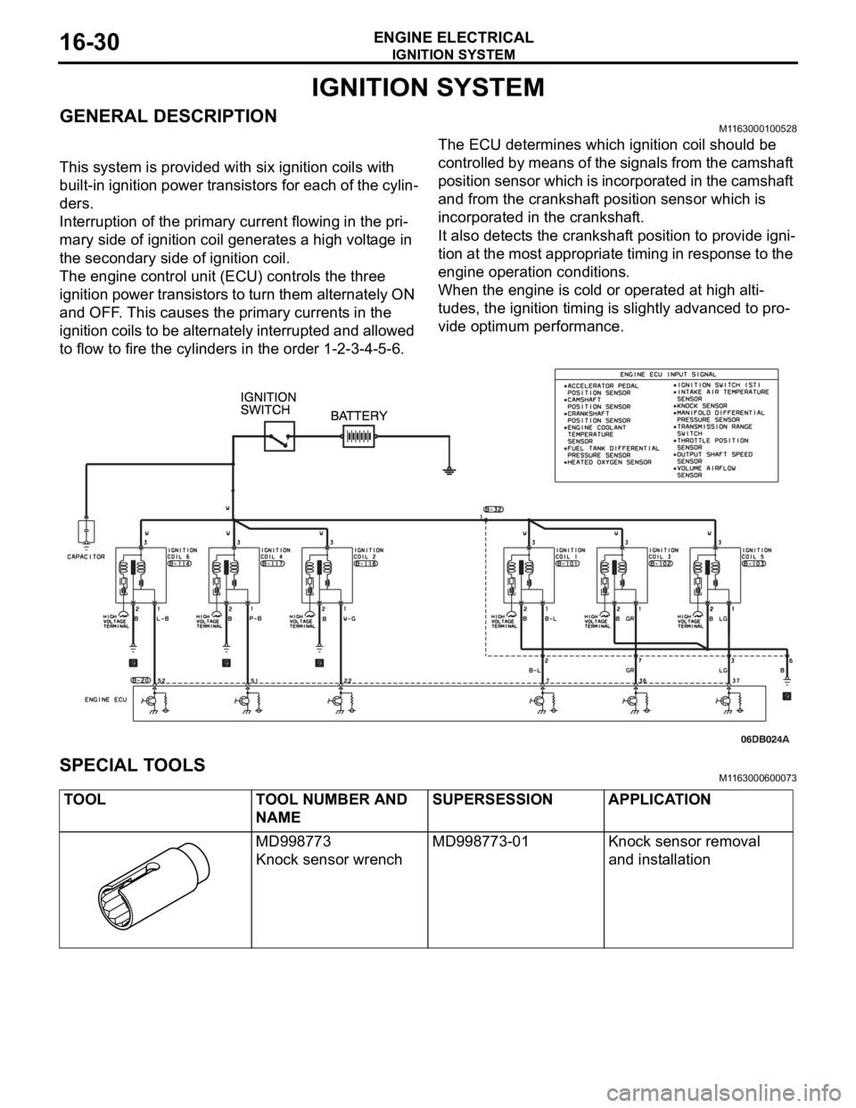
This system is provided with six ignition coils with
built-in ignition power transistors for each of the cylin-
ders.
Interruption of the primary current flowing in the pri-
mary side of ignition coil generates a high voltage in
the secondary side of ignition coil.
The engine control unit (ECU) controls the three
ignition power transistors to turn them alternately ON
and OFF. This causes the primary currents in the
ignition coils to be alternately interrupted and allowed
to flow to fire the cylinders in the order 1-2-3-4-5-6.The ECU determines which ignition coil should be
controlled by means of the signals from the camshaft
position sensor which is incorporated in the camshaft
and from the crankshaft position sensor which is
incorporated in the crankshaft.
It also detects the crankshaft position to provide igni-
tion at the most appropriate timing in response to the
engine operation conditions.
When the engine is cold or operated at high alti-
tudes, the ignition timing is slightly advanced to pro-
vide optimum performance.
SPECIAL TOOLSM1163000600073
TOOL TOOL NUMBER AND
NAMESUPERSESSION APPLICATION
MD998773
Knock sensor wrenchMD998773-01 Knock sensor removal
and installation
Page 1008 of 1500

IGNITION SYSTEM
ENGINE ELECTRICAL16-31
ON-VEHICLE SERVICE
KNOCK CONTROL SYSTEM CHECKM1163001800081
Check the knock sensor circuit if diagnostic trouble code, No.
P0325 is shown.
Refer to GROUP 13B, Multiport Fuel Injection (MPI)
Multiport
Fuel Injection (MPI) Diagnosis
Diagnostic Trouble Code Pro-
cedures
DTC P0325 : Knock Sensor Circuit 13A-346.
IGNITION COIL CHECK M1163001200380
Check by the following procedure, and replace the coil if there
is a malfunction.
.
PRIMARY COIL AND IGNITION POWER
TRANSISTOR CONTINUITY CHECK
NOTE: No test can be performed on the Primary side of coil.
.
SECONDARY COIL CHECK
NOTE: It is impossible to check the secondary coil through the
continuity check as a diode is integrated in the secondary coil
circuit of this ignition coil. Accordingly, check the secondary coil
in the following procedure.
1. Disconnect the ignition coil connector.
2. Remove the ignition coil and install a new spark plug to the
ignition coil.
3. Connect the ignition coil connector.
4. Disable vehicle fuel pump by removing fuel pump relay or
disconnecting fuel pump connector D-18 (under rear seat).
5. Ground the side electrode of the spark plug and crank the
engine.
6. Check that spark is produced between the electrodes of the
spark plug.
7. If no spark is produced, replace the ignition coil with a new
one and recheck.
8. If spark is produced with the new ignition coil, replace the
old one as it is faulty. If no spark is produced again, the
ignition circuit is suspected as faulty. Check the ignition
circuit.
Page 1009 of 1500

IGNITION SYSTEM
ENGINE ELECTRICAL16-32
SPARK PLUG TESTM1163001500143
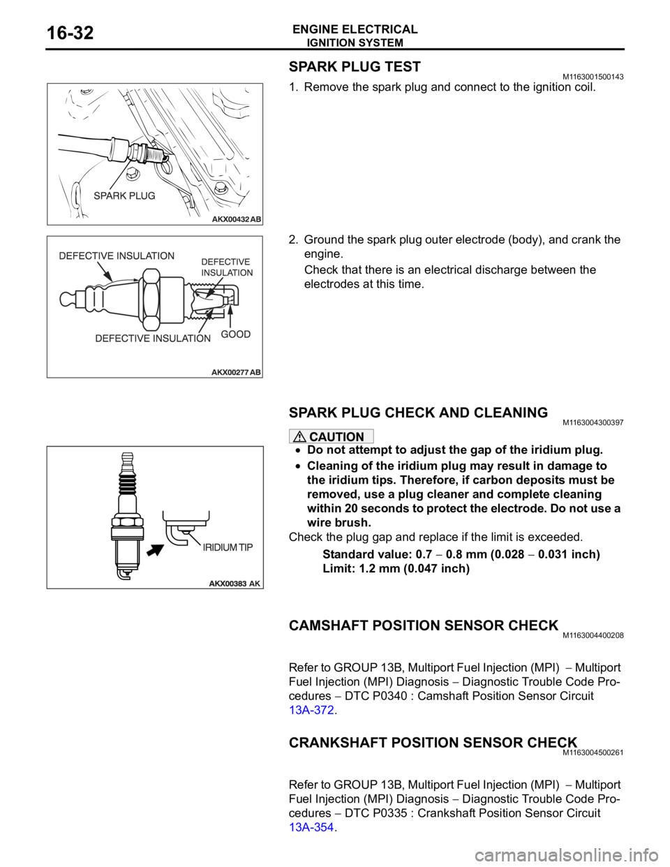
1. Remove the spark plug and connect to the ignition coil.
2. Ground the spark plug outer electrode (body), and crank the
engine.
Check that there is an electrical discharge between the
electrodes at this time.
SPARK PLUG CHECK AND CLEANING M1163004300397
Do not attempt to adjust the gap of the iridium plug.
Cleaning of the iridium plug may result in damage to
the iridium tips. Therefore, if carbon deposits must be
removed, use a plug cleaner and complete cleaning
within 20 seconds to protect the electrode. Do not use a
wire brush.
Check the plug gap and replace if the limit is exceeded.
Standard value: 0.7
0.8 mm (0.028 0.031 inch)
Limit: 1.2 mm (0.047 inch)
CAMSHAFT POSITION SENSOR CHECKM1163004400208
Refer to GROUP 13B, Multiport Fuel Injection (MPI) Multiport
Fuel Injection (MPI) Diagnosis
Diagnostic Trouble Code Pro-
cedures
DTC P0340 : Camshaft Position Sensor Circuit
13A-372.
CRANKSHAFT POSITION SENSOR CHECKM1163004500261
Refer to GROUP 13B, Multiport Fuel Injection (MPI) Multiport
Fuel Injection (MPI) Diagnosis
Diagnostic Trouble Code Pro-
cedures
DTC P0335 : Crankshaft Position Sensor Circuit
13A-354.
Page 1010 of 1500
IGNITION SYSTEM
ENGINE ELECTRICAL16-33
IGNITION COIL
REMOVAL AND INSTALLATION M1163004000448
REMOVAL STEPS
ENGINE COVER (REFER TO
GROUP 11C, ENGINE ASSEMBLY
11A-14).
1. IGNITION COIL CONNECTORS
(LH)
2. IGNITION COILS (LH)
3. SPARK PLUGS (LH)INTAKE MANIFOLD PLENUM
(REFER TO GROUP 15, INTAKE
MANIFOLD PLENUM P.15-5).
4. IGNITION COIL CONNECTORS
(RH)
5. IGNITION COILS (RH)
6. SPARK PLUGS (RH)REMOVAL STEPS (Continued)
Page 1015 of 1500

SPECIFICATIONS
ENGINE ELECTRICAL16-38
SPECIFICATIONS
FASTENER TIGHTENING SPECIFICATIONSM1161002100506
GENERAL SPECIFICATIONSM1161000200411
ITEM SPECIFICATION
Charging system
Alternator bracket bolt49
9 Nm (36 7 ft-lb)
Alternator bolt49
9 Nm (36 7 ft-lb)
Alternator terminal nut12
2 Nm (102 22 in-lb)
Ignition system
Camshaft position sensor bolt 11
1 Nm (98 8 in-lb)
Crankshaft position sensor bolt 9.0
1.0 Nm (80 9 in-lb)
Ignition coil bolt 10
2 Nm (89 17 in-lb)
Knock sensor 23
2 Nm (17 1 ft-lb)
Spark plug 25
4 Nm (18 3 ft-lb)
Starting system
Starter bolt 30
3 Nm (23 2 ft-lb)
Starter cover bolt 4.9
1.0 Nm (44 8 in-lb)
Starter terminal nut 12
2 Nm (102 22 in-lb)
ITEMS SPECIFICATIONS
Alternator
Type Positive battery positive voltage sensing
Identification number
Part No. MN180394
Rated output V/A 12/110
Voltage regulator Electronic built-in type
Starter Motor
Type Reduction drive with planetary gear
Identification number M000T31172
Part No. 1810A090
Rated output kW/V 1.2/12
Number of pinion teeth 8
Ignition Coil
Type Molded 6 coil
Spark Plugs
BOSCH FR8DI30
Page 1016 of 1500
SPECIFICATIONS
ENGINE ELECTRICAL16-39
SERVICE SPECIFICATIONSM1161000300322
ITEMS STANDARD VALUE LIMIT
Alternator
Regulated voltage
(Ambient temperature at voltage
regulator)
20C (4F)14.2 15.4
20C (68F) 13.9 14.9
60C (140F) 13.4 14.5
80C (176F) 13.1 14.5
Alternator output wire voltage drop (at 30 A) VMaximum 0.3
Nominal Output current 110A 70 % of normal output
current
Field coil resistance
Approximately 2 5
Brush protrusion length mm (in)Minimum 2 (0.08)
Starter motor
Free running characteristics Terminal voltage
V11
Current A 95
Speed r/min 2,500 or more
Pinion gap mm (in) 0.5 2.0 (0.02 0.07)
Commutator run-out mm (in) 0.05 (0.002) Minimum 0.1 (0.004)
Commutator diameter mm (in) 29.4 (1.16) Minimum 28.8 (1.13)
Undercut depth mm (in) 0.5 (0.02) Minimum 0.2 (0.008)
Ignition parts
Spark plug gap mm 1.0 1.1