Page 1180 of 1500

ON-VEHICLE SERVICE
BASIC BRAKE SYSTEM35A-15
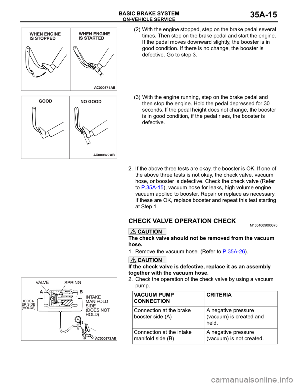
(2) With the engine stopped, step on the brake pedal several
times. Then step on the brake pedal and start the engine.
If the pedal moves downward slightly, the booster is in
good condition. If there is no change, the booster is
defective. Go to step 3.
(3) With the engine running, step on the brake pedal and
then stop the engine. Hold the pedal depressed for 30
seconds. If the pedal height does not change, the booster
is in good condition, if the pedal rises, the booster is
defective.
2. If the above three tests are okay, the booster is OK. If one of
the above three tests is not okay, the check valve, vacuum
hose, or booster is defective. Check the check valve (Refer
to P.35A-15), vacuum hose for leaks, high volume engine
vacuum applied to booster. Repair or replace as necessary.
If these are OK, replace booster and repeat this test starting
at Step 1.
CHECK VALVE OPERATION CHECKM1351009000376
The check valve should not be removed from the vacuum
hose.
1. Remove the vacuum hose. (Refer to P.35A-26).
If the check valve is defective, replace it as an assembly
together with the vacuum hose.
2. Check the operation of the check valve by using a vacuum
pump.
VACUUM PUMP
CONNECTIONCRITERIA
Connection at the brake
booster side (A)A negative pressure
(vacuum) is created and
held.
Connection at the intake
manifold side (B)A negative pressure
(vacuum) is not created.
Page 1189 of 1500
BRAKE PEDAL
BASIC BRAKE SYSTEM35A-24
BRAKE PEDAL
REMOVAL AND INSTALLATIONM1351003400406
Post-installation Operation
Brake Pedal Adjustment (Refer to P.35A-13).
REMOVAL STEPS
1. BRAKE BOOSTER PIN
2. BRAKE BOOSTER PIN ASSEMBLY
3. SHIFT LOCK CABLE CONNECTION
4. STOPLIGHT SWITCH CONNECTOR
5. STOPLIGHT SWITCH
6. BRAKE PEDAL CLIPWIRING HARNESSES CLAMPED
ON BRAKE PEDAL ASSEMBLY
7. BRAKE PEDAL BOLT
8. BRAKE BOOSTER NUT
9. BRAKE PEDAL ASSEMBLY
10. BRAKE PEDAL PAD
11. BRAKE PEDAL STOPPERREMOVAL STEPS (Continued)
Page 1190 of 1500
BRAKE PEDAL
BASIC BRAKE SYSTEM35A-25
INSPECTIONM1351003500221.
STOPLIGHT SWITCH CHECK
1. Connect an ohmmeter between the stoplight switch
connector terminals.
2. There should be no continuity between the terminals when
the plunger is pushed in as shown. There should be
continuity when it is released.
TESTER
CONNECTIONPLUNGER SPECIFIED
CONDITION
1
2 IN Open circuit
OUT Less than 2
Page 1302 of 1500

TRACTION CONTROL SYSTEM (TCL) DIAGNOSIS
TRACTION CONTROL SYSTEM (TCL)13C-23
SYMPTOM CHARTM1136003400029
SYMPTOM PROCEDURES
INSPECTION PROCEDURE 1: When the Ignition Switch is Turned to the "ON" Position
(Engine Stopped), the "TCL OFF" Indicator Light does not Illuminate. INSPECTION
PROCEDURE 2: When the Ignition Switch is Turned to the "ON" Position (Engine
Stopped), the TCL Work Indicator Light dose not Illuminate. INSPECTION
PROCEDURE 3: The "TCL OFF" Indicator Light Remains Illuminated After the Engine
is Started. INSPECTION PROCEDURE 4: The TCL Work Indicator Light Remains
Illuminated After the Engine is Started.
SYMPTOM INSPECTION
PROCEDURE NO.REFERENCE
PA G E
Communication with
diagnostic tool is not
possibleCommunication with all systems is
impossible- Group 13A, MPI
Diagnosis
Symptom
Procedures
Inspection
Procedure 1
P.13A-539.
Communication with the ABS/TCL-ECU
only is impossible- Group 35B, ABS
Diagnosis
Symptom
Procedures
Inspection
Procedure 1
P.35B-72.
When the ignition switch is turned to the "ON" position (engine
stopped), the "TCL OFF" indicator light dose not illuminate.1
P.13C-23
When the ignition switch is turned to the "ON" position (engine
stopped), the TCL work indicator light does not illuminate.2
The "TCL OFF" indicator light remains illuminated after the engine
is started.3
The TCL work indicator light remains illuminated after the engine
is started.4
When the TCL switch is push on, TCL does not be cancelled. 5
P.13C-28
TCL dose not operate. 6
P.13C-34
Page 1315 of 1500

TRACTION CONTROL SYSTEM (TCL) DIAGNOSIS
TRACTION CONTROL SYSTEM (TCL)13C-36
DATA LIST REFERENCE TABLEM1136003500071
NOTE: If the ABS-8 ECU or the active wheel
speed sensor are disconnected, or if the wiring is
an open/ short circuit, the ABS 8 ECU will shut
off power supply to the respective wheel speed
sensor. All other wheel speed sensors will oper-
ate normally. To restore the power supply, the
ignition switch must be turned to the "OFF" posi-
tion then to the "ON" position again.The following items can be read by the diagnostic
tool from the ABS/TCL-ECU input data. (Refer to
P.13C-3).
NOTE: Since the TCL is controlled with the same ABS/TCL-ECU used to control the ABS, the stoplight switch
check item (No.6) used only for the ABS also appear.MUT-III
DIAGNOSTI
C TOOL
DISPLAYITEM
NO.CHECK ITEM CHECKING REQUIREMENTS NORMAL
VA L U E
FL wheel
speed sensor01 Front left wheel speed sensor Drive the vehicle Vehicle speeds
displayed on the
speedometer
and diagnostic
tool are identical. FR wheel
speed sensor02 Front right wheel speed sensor
RL wheel
speed sensor03 Rear left wheel speed sensor
RR wheel
speed sensor04 Rear right left wheel speed
sensor
Power supply
voltage05 ABS/TCL-ECU power supply
voltageIgnition switch power supply
voltageBattery positive
voltage
Stoplamp
switch
(input)*06 Stoplamp switch Depress the brake pedal. ON
Release the brake pedal. OFF
Stoplamp
switch*13 Stoplamp switch Depress the brake pedal. ON
Release the brake pedal. OFF
Pump motor 21 Pump motor When the ABS outputs the
operation permission signal
during drivingON
When the ABS outputs the
operation permission signal
during drivingOFF
Valve relay 30 Valve relayWhen the ABS outputs the
operation permission signal
during drivingON
When the ABS outputs the
operation permission signal
during drivingOFF
TCL mode 35 TCL operation When the TCL outputs the
operation permission signal
during drivingON
When the TCL outputs the
operation inhibition signal
during drivingOFF
Page 1396 of 1500

AUTO-CRUISE CONTROL
ENGINE AND EMISSION CONTROL17-65
DATA LIST REFERENCE TABLE - Auto Cruise ControlM1172002400471
When shifting the selector lever to "D" range, apply the brakes so that the vehicle does not move
forward.
Driving tests always need two persons: one driver and one observer.
NOTE: *:After the inspection is completed, disconnect the throttle position sensor connector, and then delete
the diagnostic trouble code using use of Diagnostic Tool MB991958. (Refer to P.17-11).
MUT-III
Diagnostic
To o l
DISPLAYITEM
NO.INSPECTION ITEM INSPECTION REQUIREMENT NORMAL
CONDITION
APS
SNS(MAIN)11 A c c e l e r a t o r p e d a l
position sensor (main)Ignition
switch:
"ON"Accelerator pedal: Released
435
1,035 mV
Accelerator pedal: Gradually
depressedIncreases in
response to the
pedal depression
stroke
Accelerator pedal: Fully
depressed4,000 mV or more
BRAKE SW 89 Stoplamp switch Brake pedal: Depressed ON
Brake pedal: Released OFF
CANCEL
CODE57 Cancel code Ignition switch: "ON" The cancel code,
which set when the
auto-cruise control
system was
cancelled at the
last time, is set
again.
CANCEL
SWITCH75 Auto-cruise
control
switchCANCEL "CANCEL" switch: ON ON
"CANCEL" switch: OFF OFF
CLUTCH SW 78 Transmission inhibitor
switchTransmission inhibitor switch: "P" or
"N"ON
Transmission inhibitor switch: Other
than aboveOFF
CRUISE 81 Auto-cruise control
system operationAuto-cruise control system: active ON
Auto-cruise control system: Inactive OFF
MAIN SW 86 Auto-cruise
control
switchCRUISE
(MAIN)"CRUISE" (MAIN) switch: "ON" ON
"CRUISE" (MAIN) switch: "OFF" OFF
RESUME
SWITCH91 Auto-cruise
control
switchACC/RES "ACC/RES" switch: ON ON
"ACC/RES" switch: OFF OFF
SET SWITCH 92 Auto-cruise
control
switchCOAST/S
ET"COAST/SET" switch: ON ON
"COAST/SET" switch: OFF OFF
STOPLIGHT
SW74 Stoplamp switch Brake pedal: Depressed ON
Brake pedal: Released OFF
Page 1404 of 1500

AUTO-CRUISE CONTROL
ENGINE AND EMISSION CONTROL17-73
AUTO-CRUISE CONTROL SYSTEM COMPONENT
CHECK
M1172001700316
AUTO-CRUISE CONTROL SWITCH CHECK
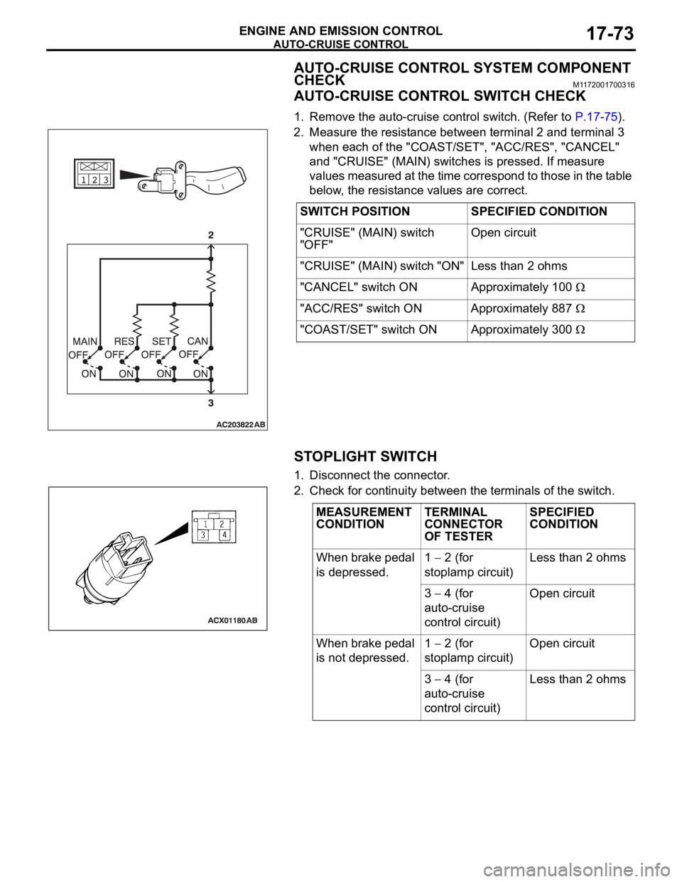
1. Remove the auto-cruise control switch. (Refer to P.17-75).
2. Measure the resistance between terminal 2 and terminal 3
when each of the "COAST/SET", "ACC/RES", "CANCEL"
and "CRUISE" (MAIN) switches is pressed. If measure
values measured at the time correspond to those in the table
below, the resistance values are correct.
STOPLIGHT SWITCH
1. Disconnect the connector.
2. Check for continuity between the terminals of the switch.SWITCH POSITION SPECIFIED CONDITION
"CRUISE" (MAIN) switch
"OFF"Open circuit
"CRUISE" (MAIN) switch "ON" Less than 2 ohms
"CANCEL" switch ON Approximately 100
"ACC/RES" switch ON Approximately 887
"COAST/SET" switch ON Approximately 300
MEASUREMENT
CONDITIONTERMINAL
CONNECTOR
OF TESTERSPECIFIED
CONDITION
When brake pedal
is depressed.1
2 (for
stoplamp circuit)Less than 2 ohms
3
4 (for
auto-cruise
control circuit)Open circuit
When brake pedal
is not depressed.1
2 (for
stoplamp circuit)Open circuit
3
4 (for
auto-cruise
control circuit)Less than 2 ohms
Page 1406 of 1500
AUTO-CRUISE CONTROL
ENGINE AND EMISSION CONTROL17-75
AUTO-CRUISE CONTROL
REMOVAL AND INSTALLATIONM1172001400467
Before removal of the air bag module, refer to GROUP 52B, SRS Service Precautions
P.52B-16 and GROUP 52B, Air Bag Module and Clock Spring P.52B-237.
CONTROL SWITCH REMOVAL
STEPS
1. AIR BAG MODULE
SIDE> (REFER TO GROUP 52B, AIR
BAG MODULES AND CLOCK
SPRING P.52B-237)
2. STEERING WHEEL ASSEMBLY
(REFER TO GROUP 37, STEERING
WHEEL P.37-23)
3. LOWER COVER CAP
4. AUTO-CRUISE CONTROL SWITCH
CONTROL UNIT REMOVAL
5. Engine ECU [REFER TO GROUP
13A, Engine ECU 13A-675] SENSOR REMOVAL STEPS
6. TRANSMISSION INHIBITOR
SWITCH (REFER TO GROUP 23B,
AUTOMATIC TRANSMISSION)
7. THROTTLE BODY (BUILT-IN
THROTTLE POSITION SENSOR
AND THROTTLE ACTUATOR
CONTROL MOTOR) (REFER TO
GROUP 13A, THROTTLE BODY
13A-660)
8. ACCELERATOR PEDAL (BUILT-IN
ACCELERATOR PEDAL POSITION
SENSOR) (REFER TO GROUP 17,
ACCELERATOR PEDAL P.17-9)
9. STOPLIGHT SWITCH (REFER TO
GROUP 35A, BRAKE PEDAL
P.35A-24)