Page 590 of 1500

CENTRALISED JUNCTION
CIRCUIT DIAGRAMS90-13
19 Front-ECU (Field
effect transistor for
headlamp: Low)Fuse 10 Red Headlamp (LH) and headlamp (Low:
LH)
20 Front-ECU (Taillamp
relay)7.5 Brown A/C-ECU, A/T selector lever position
illumination lamp, combination meter,
fog lamp switch, headlamp (RH),
glove box lamp, hazard warning lamp
switch, multi-center display unit,
radio, CD player, rear combination
lamp (RH), rheostat and TCL switch
21 7.5 Brown Headlamp (LH), license plate lamp
and rear combination lamp (LH)
22 Battery/Alternator
(Fusible link No.27)15 Blue A/C-ECU, column switch,
combination meter, ETACS-ECU,
front-ECU, key reminder switch, multi-
center display unit, radio, CD player,
and vanity mirror lamp
23 Ignition switch (ACC) 10 Red A/C-ECU, accessory socket relay,
ETACS-ECU, multi-center display
unit, radio, CD player.
24 Battery/Alternator
(Fusible link No.27)15 Blue Fuel pump module
25 Ignition switch (ACC) 30 Green Front-ECU and windshield wiper
motor
26 Battery/Alternator
(Fusible link No.27)Fusible
link20 Light blue Anti-lock braking system(solenoid
valve)
27
Alternator120
Battery, front-ECU, fusible link Nos.1,
2, 3, 4, 5 and 26 and fuse Nos.6, 7, 8,
9, 10, 11, 13, 14, 15, 22 and 24 (in
relay box) NO. POWER SUPPLY
CIRCUITNAME RATED
CAPACITY (A)HOUSING
COLOURLOAD CIRCUIT
Page 592 of 1500

CENTRALISED JUNCTION
CIRCUIT DIAGRAMS90-15
NO. POWER SUPPLY
CIRCUITNAME RATED
CAPACITY (A)HOUSING
COLOURLOAD CIRCUIT
1 Fusible link No.1 Fuse 30 Green Rear window demister
2 30 Green Blower motor and resistor
3
4
5 15 Blue Accessory socket
6 15 Blue Data link connector and ETACS-ECU
7 Ignition switch (ACC) 15 Blue ETACS-ECU
8
9 Ignition switch (IG2) 7.5 Brown Sunroof assembly
10 Ignition switch (ACC) 7.5 Brown Remote controlled mirror
11
12
13 Ignition switch (IG1) 7.5 Brown Fuel pump relay and Engine ECU
14 Ignition switch (ACC) 20 Yellow Windscreen wiper
15 Fusible link No.1
(Fuse No.5 in junction
block)7.5 Brown Remote controlled mirror
16 Ignition switch (IG2) 7.5 Brown A/C compressor clutch relay,
A/C-ECU, blower relay, condenser
fan motor, fan control relay,
front-ECU, outside/inside air selection
damper control motor and rear
window defogger relay
17 Ignition switch (IG1)
18 7.5 Brown A/T control relay, input shaft speed
sensor, output shaft speed sensor,
Engine ECU, rear combination lamp
and SRS-ECU
19 7.5 Brown ABS-ECU, ABS/TCL-ECU, column
switch, combination meter,
ETACS-ECU, multi-center display unit
and SRS-ECU
20 10 Red Ignition coil
21
22
23 Fusible link No.5 20 Yellow Sunroof assembly
24
Page 1078 of 1500
FUEL FILLER LID
BODY42-11
FUEL FILLER LID
REMOVAL AND INSTALLATIONM1421002500288
REMOVAL
1. FUEL FILLER CAP2. FUEL FILLER LID
3. FUEL FILLER LID DAMPERREMOVAL (Continued)
Page 1223 of 1500

GENERAL00-2
MAINTENANCE SERVICE . . . . . . . .00-37
1. FUEL SYSTEM (TANK, PIPE LINE AND
CONNECTION, AND FUEL TANK FILLER
TUBE CAP) (CHECK FOR LEAKS) . . . . . . 00-37
2. FUEL HOSES (CHECK CONDITION) . . 00-37
3. AIR CLEANER FILTER (REPLACE). . . . 00-37
4. EVAPORATIVE EMISSION SYSTEM
(EXCEPT EVAPORATIVE EMISSION
CANISTER) (CHECK FOR CLOGGING) . . 00-37
5. SPARK PLUGS (REPLACE). . . . . . . . . . 00-38
7. TIMING BELT (REPLACE) . . . . . . . . . . . 00-38
8. DRIVE BELTS (FOR ALTERNATOR, POWER
STEERING PUMP AND AIR CONDITIONING)
(CHECK) . . . . . . . . . . . . . . . . . . . . . . . . . . . 00-39
9. EXHAUST SYSTEM (CONNECTIONS
PORTION OF MUFFLER, MUFFLER PIPES
AND CONVERTER HEAT SHIELDS) (CHECK
AND SERVICE AS REQUIRED) . . . . . . . . . 00-44
10. ENGINE OIL (CHANGE) . . . . . . . . . . . . 00-4411. ENGINE OIL FILTER (REPLACE) . . . . 00-44
12. TRANSMISSION FLUID . . . . . . . . . . . . 00-45
13. ENGINE COOLANT (CHANGE) . . . . . . 00-47
14. COOLANT HOSES (RADIATOR HOSE,
HEATER HOSE) (INSPECT). . . . . . . . . . . . 00-49
15. DISC BRAKE PADS, ROTORS
(INSPECT FOR WEAR) . . . . . . . . . . . . . . . 00-49
16. BRAKE HOSES (CHECK FOR
DETERIORATION OR LEAKS) . . . . . . . . . . 00-49
17. BALL JOINT AND STEERING LINKAGE
SEALS (INSPECT FOR GREASE LEAKS
AND DAMAGE) . . . . . . . . . . . . . . . . . . . . . . 00-50
18. DRIVE SHAFT BOOTS (INSPECT FOR
GREASE LEAKS AND DAMAGE) . . . . . . . . 00-50
19. SUSPENSION SYSTEM (INSPECT FOR
LOOSENESS AND DAMAGE) . . . . . . . . . . 00-51
20. SRS AIR BAG (INSPECT FOR SRS
SYSTEM). . . . . . . . . . . . . . . . . . . . . . . . . . . 00-51
21. TYRES (ROTATE). . . . . . . . . . . . . . . . . 00-58
Page 1256 of 1500
RECOMMENDED LUBRICANTS AND LUBRICANT CAPACITIES TABLE
GENERAL00-35
RECOMMENDED LUBRICANTS AND LUBRICANT
CAPACITIES TABLE
M1001001300504
RECOMMENDED LUBRICANTS
LUBRICANT CAPACITY TABLE
<3.8L ENGINE>LUBRICANT SPECIFICATION
Engine oil Engine oils conforming to ACEA A1, A2 or A3 and
AP1 SG or higher
AutomaticTransmission fluid Genuine Mitsubishi Motors ATF-SP III
Manual Transmission fluid Genuine Mitsubishi Motors MTF
Power steering fluid ATF DEXRON III or DEXRON II
Brakes fluid Conforming to DOT 3 or DOT 4
Engine coolant Genuine Mitsubishi Motors coolant
Refrigerant (air conditioning) HFC-134a
DESCRIPTION SPECIFICATION
Engine oil (Litres) Oil pan (excluding oil filter) 4.0
Oil filter 0.3
Engine coolant (Litres) 8.7
Automatic Transmission fluid (Litres) 8.4
Manual Transmission fluid (Litres) 2.8
Power steering fluid (Litres) 1.2
Fuel tank (Litres) 67.0
Washer fluid (Litres) 5.0
Refrigerant (air conditioning) (grams) 435g - 475g
Page 1258 of 1500

MAINTENANCE SERVICE
GENERAL00-37
MAINTENANCE SERVICE
1. FUEL SYSTEM (TANK, PIPE LINE AND
CONNECTION, AND FUEL TANK FILLER TUBE
CAP) (CHECK FOR LEAKS)
M1001001600312
Check for damage or leakage in the fuel lines and connections.
2. FUEL HOSES (CHECK CONDITION)M1001001700308
1. Inspect the surface of fuel hoses for heat and mechanical
damage. Hard and brittle rubber, cracking, tears, cuts,
abrasions and excessive swelling indicate deterioration of
the rubber.
2. If the fabric casing of the rubber hose is exposed by cracks
and abrasions in the fuel system, the hose should be
replaced.
3. AIR CLEANER FILTER (REPLACE)M1001001800338
The air cleaner element will become dirty during use, reducing
its effectiveness. Replace it with a new one.
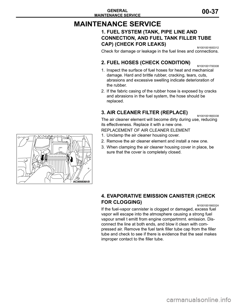
REPLACEMENT OF AIR CLEANER ELEMENT
1. Unclamp the air cleaner housing cover.
2. Remove the air cleaner element and install a new one.
3. When clamping the air cleaner housing cover in place, be
sure that the cover is completely closed.
4. EVAPORATIVE EMISSION CANISTER (CHECK
FOR CLOGGING)
M1001001900324
If the fuel-vapor cannister is clogged or damaged, excess fuel
vapor will escape into the atmosphere causing a strong fuel
vapour smell t emitt from engine compartmrnt. emission. Dis-
connect the line at both ends, and blow it clean with com-
pressed air. Remove the fuel tank filler tube cap from the filler
tube and check to see if there is evidence that the seal makes
improper contact to the filler tube.
Page 1412 of 1500
EMISSION CONTROL
ENGINE AND EMISSION CONTROL17-81
EVAPORATIVE EMISSION CONTROL SYSTEM
GENERAL DESCRIPTION (EVAPORATIVE EMISSION SYSTEM)M1173005100706
The evaporative emission (EVAP) system prevents
fuel vapors generated in the fuel tank from escaping
into the atmosphere.
Fuel vapors from the fuel tank flow through the vapor
pipe/hose to be stored temporarily in the EVAP can-
ister.
When the vehicle is in operation, fuel vapors stored
in the EVAP canister flow through the EVAP purge
solenoid, purge port and intake manifold plenum to
the combustion chamber.When the engine coolant temperature is low or when
the intake air quantity is small (when the engine is at
idle, for example), the Engine-ECU brings the EVAP
purge solenoid into the OFF state to shut off the fuel
vapor flow to the intake manifold plenum. This
ensures driveability when the engine is cold or run-
ning under low load and also stabilizes the emission
level.
SYSTEM DIAGRAM