Page 495 of 1500
Page 553 of 1500
ENGINE COMPARTMENT
CONFIGURATION DIAGRAMS80-4
ENGINE COMPARTMENTM1801000301403
A-01 (2-B) WHEEL SPEED SENSOR (FRONT:
RH)
A-02 (26-B) ABS-ECU OR ABS/TCL-ECU
A-03 (5-B) WINDSHIELD WIPER MOTOR
A-04 (2-B) WHEEL SPEED SENSOR (FRONT:
LH)
A-05X (4) FOG LAMP RELAY
A-06X (4) HORN RELAY
A-10X (4) FAN CONTROL RELAYA-11X (11) FRONT-ECU
A-12X (11) FRONT-ECU
A-13 (17-GR) FRONT WIRING HARNESS AND
CONTROL WIRING HARNESS
COMBINATION
A-14 (6-GR) GROUNDING CONNECTOR
A-17 (2) SIDE TURN SIGNAL LAMP (LH)
A-18 (2) FRONT TURN SIGNAL LAMP (LH)
A-20 (6) HEADLAMP COMBINATION (LH)
Page 571 of 1500
FLOOR, SEAT AND ROOF
CONFIGURATION DIAGRAMS80-22
D-26 (20-Y) SRS-ECU (FLOOR HARNESS)
D-27 (20-Y) SRS-ECU (FLOOR HARNESS)
D-28 (5-B) SEAT BELT BUCKLE SWITCH
(DRIVER’S SIDE)
D-30 (2) WHEEL SPEED SENSOR (REAR:
RH)
D-31 (2) WHEEL SPEED SENSOR (REAR:
LH)
D-32 (2-R) SIDE AIR BAG MODULE (SQUIB)
(RH)
D-33 (2-B) SEAT BELT PRETENSIONER (RH)
D-34 (3) FRONT DOOR SWITCH (RH)D-35 (2) SIDE IMPACT SENSOR (RH)
D-36 (10) FLOOR WIRING HARNESS AND
REAR DOOR WIRING HARNESS
(RH) COMBINATION
D-38 (8) POWER SEAT (MEMORY) (RH)
D-39 (2) POWER SEAT ASSEMBLY (LH)
D-39-1 (5-W) FRONT HEIGHT MOTOR
D-39-2 (5-B) REAR HEIGHT MOTOR
D-39-3 (4) SEAT SLIDE MOTOR
D-39-4 (8) SEAT ADJUST SWITCH (LH)
D-40 (1-B) CAPACITOR
Page 850 of 1500

ON-VEHICLE SERVICE
HEATER, AIR CONDITIONING AND VENTILATION55-149
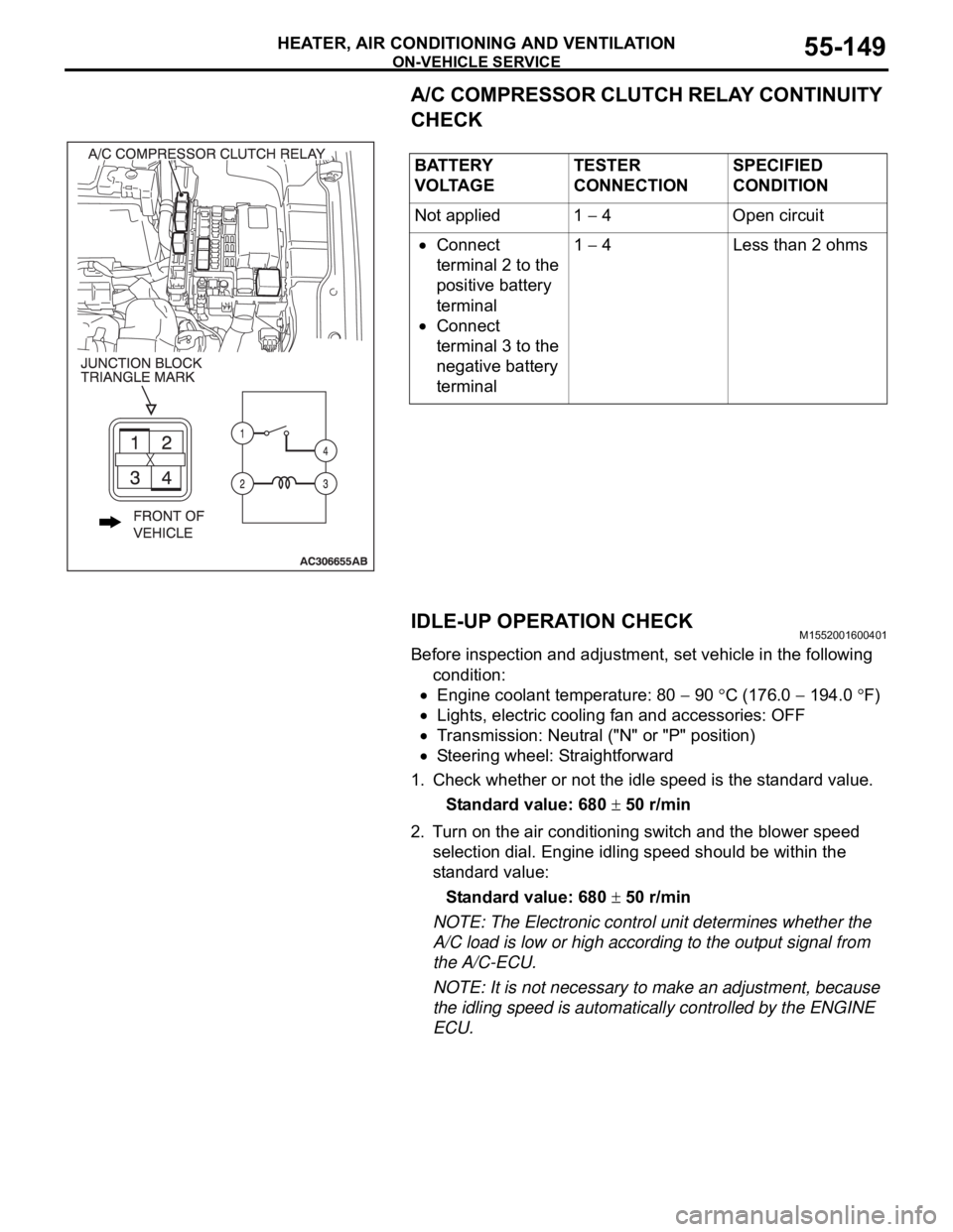
A/C COMPRESSOR CLUTCH RELAY CONTINUITY
CHECK
IDLE-UP OPERATION CHECK
M1552001600401
Before inspection and adjustment, set vehicle in the following
condition:
Engine coolant temperature: 80 90 C (176.0 194.0 F)
Lights, electric cooling fan and accessories: OFF
Transmission: Neutral ("N" or "P" position)
Steering wheel: Straightforward
1. Check whether or not the idle speed is the standard value.
Standard value: 680
50 r/min
2. Turn on the air conditioning switch and the blower speed
selection dial. Engine idling speed should be within the
standard value:
Standard value: 680
50 r/min
NOTE: The Electronic control unit determines whether the
A/C load is low or high according to the output signal from
the A/C-ECU.
NOTE: It is not necessary to make an adjustment, because
the idling speed is automatically controlled by the ENGINE
ECU. BATTERY
V O LTA G ETESTER
CONNECTIONSPECIFIED
CONDITION
Not applied 1
4 Open circuit
Connect
terminal 2 to the
positive battery
terminal
Connect
terminal 3 to the
negative battery
terminal1
4 Less than 2 ohms
Page 888 of 1500
SENSOR
COMPONENT LOCATIONS70-9
NOTE: The * symbols indicate equipped at both sides.Engine coolant temperature sensor F Throttle body assembly (Incorporating
throttle position sensor)E
Front impact sensor M Wheel speed sensor (front) Y
Side impact sensor a Wheel speed sensor (rear) b NAME SYMBOL NAME SYMBOL
Page 1026 of 1500

CROSSMEMBER
POWER PLANT MOUNT32-9
CROSSMEMBER
REMOVAL AND INSTALLATIONM1321003200551
Before removing the steering wheel and air bag module assembly, always refer to GROUP 52B -
Service Precautions (P.52B-16), Air bag Module and Clock Spring (P.52B-237). Also, set the front
wheels so that they are facing straight forward, and remove the ignition key. If you fail to do this,
the SRS clock spring will be damaged, causing the SRS air bag to be inoperative and serious
injury.
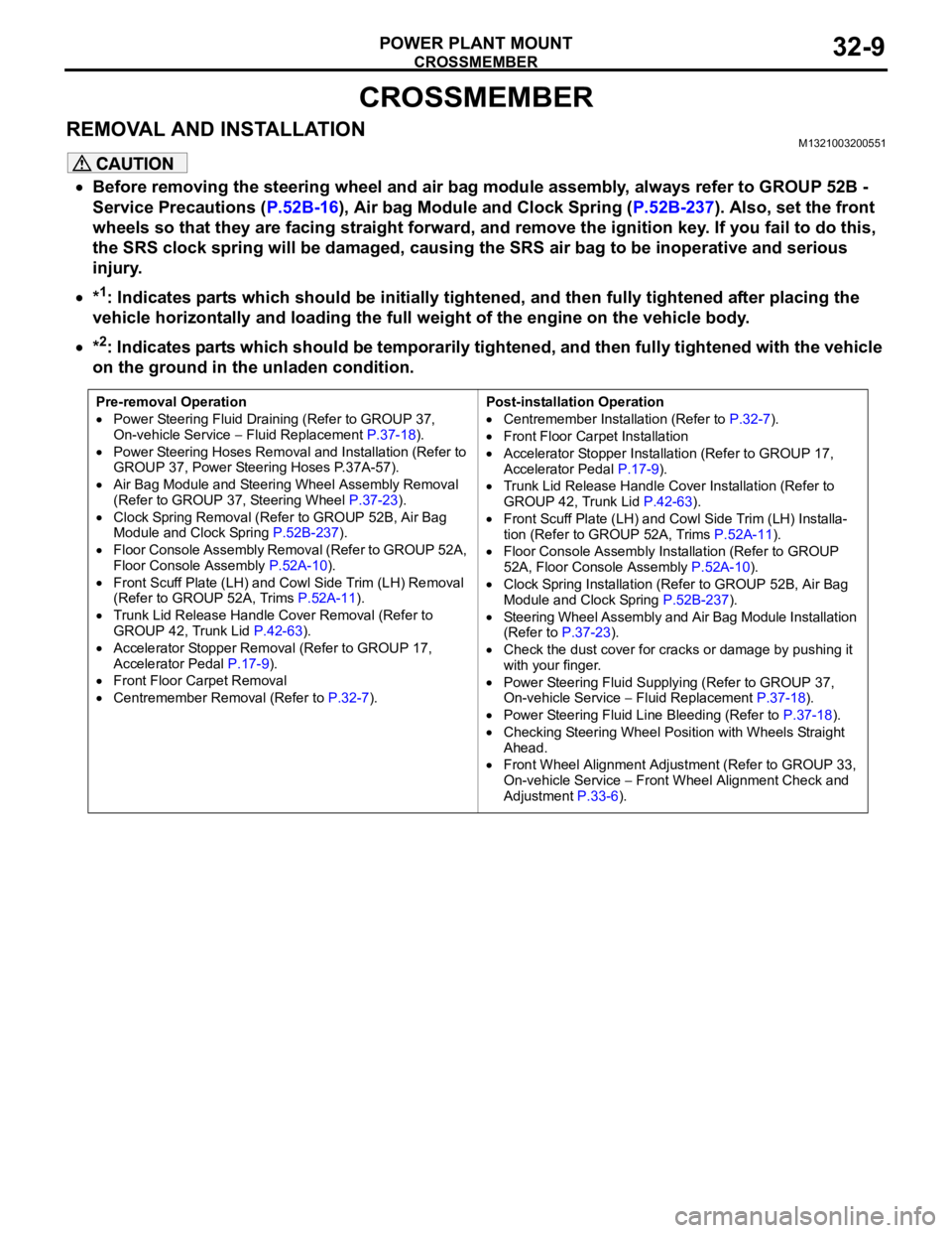
*1: Indicates parts which should be initially tightened, and then fully tightened after placing the
vehicle horizontally and loading the full weight of the engine on the vehicle body.
*2: Indicates parts which should be temporarily tightened, and then fully tightened with the vehicle
on the ground in the unladen condition.
Pre-removal Operation
Power Steering Fluid Draining (Refer to GROUP 37,
On-vehicle Service Fluid Replacement P.37-18).
Power Steering Hoses Removal and Installation (Refer to
GROUP 37, Power Steering Hoses P.37A-57).
Air Bag Module and Steering Wheel Assembly Removal
(Refer to GROUP 37, Steering Wheel P.37-23).
Clock Spring Removal (Refer to GROUP 52B, Air Bag
Module and Clock Spring P.52B-237).
Floor Console Assembly Removal (Refer to GROUP 52A,
Floor Console Assembly P.52A-10).
Front Scuff Plate (LH) and Cowl Side Trim (LH) Removal
(Refer to GROUP 52A, Trims P.52A-11).
Trunk Lid Release Handle Cover Removal (Refer to
GROUP 42, Trunk Lid P.42-63).
Accelerator Stopper Removal (Refer to GROUP 17,
Accelerator Pedal P.17-9).
Front Floor Carpet Removal
Centremember Removal (Refer to P.32-7).Post-installation Operation
Centremember Installation (Refer to P.32-7).
Front Floor Carpet Installation
Accelerator Stopper Installation (Refer to GROUP 17,
Accelerator Pedal P.17-9).
Trunk Lid Release Handle Cover Installation (Refer to
GROUP 42, Trunk Lid P.42-63).
Front Scuff Plate (LH) and Cowl Side Trim (LH) Installa-
tion (Refer to GROUP 52A, Trims P.52A-11).
Floor Console Assembly Installation (Refer to GROUP
52A, Floor Console Assembly P.52A-10).
Clock Spring Installation (Refer to GROUP 52B, Air Bag
Module and Clock Spring P.52B-237).
Steering Wheel Assembly and Air Bag Module Installation
(Refer to P.37-23).
Check the dust cover for cracks or damage by pushing it
with your finger.
Power Steering Fluid Supplying (Refer to GROUP 37,
On-vehicle Service Fluid Replacement P.37-18).
Power Steering Fluid Line Bleeding (Refer to P.37-18).
Checking Steering Wheel Position with Wheels Straight
Ahead.
Front Wheel Alignment Adjustment (Refer to GROUP 33,
On-vehicle Service
Front Wheel Alignment Check and
Adjustment P.33-6).
Page 1167 of 1500

GENERAL DESCRIPTION
BASIC BRAKE SYSTEM35A-2
GENERAL DESCRIPTIONM1351000100440
The brake system has been designed to give greater
reliability and durability and to provide excellent brak-
ing performance.
FEATURES
.
Improved braking performance
1. An 8+9 inch tandem brake booster provides suffi-
cient braking force in sudden braking range.
2. 296mm front ventilated disc brakes provide sta-
ble braking force and improved braking feel.
3. 303mm rear ventillated disc brakes are used.
.
Improved stability
1. A 4-wheel anti-lock braking system (4ABS) pre-
vents slipping caused by the vehicle wheels lock-
ing up, in order to maintain a stable vehicle
posture and steering performance.
2. An electronic brake-force distribution (EBD)
makes it possible to maintain the maximum
amount of braking force even when the vehicle's
load is unevenly distributed. 3. Front- and rear-wheel X-type brake line layout
are used.
4. Ventilated discs brakes improve anti-fading per-
formance.
.
Improved serviceability
1. A diagnosis function for the ABS system makes
inspection easier.
2. An outer disc separated hub and rotor make
removal and installation easier.
3. The master cylinder reservoir is utilised for both
brake and clutch fluid on manual transmission
vehicles.
4. The master cylinder filter is coloured black for
improved viewing.
5. The ABS-ECU and hydraulic unit are integrated
to make them more compact and light weight.
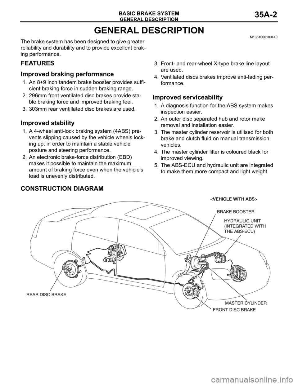
CONSTRUCTION DIAGRAM
Page 1172 of 1500

BASIC BRAKE SYSTEM DIAGNOSIS
BASIC BRAKE SYSTEM35A-7
STEP 6. Check the master cylinder piston return spring for
damage and return port for clogging.
Refer to P.35A-28.
Q: Is there damage?
YES : Replace the part. Then go to Step 9.
NO : Go to Step 7.
STEP 7. Check port for clogging.
Q: Is the port clogged?
YES : Repair it. Then go to Step 9.
NO : Go to Step 8.
STEP 8. Check disc brake pistons for sticking.
Depress the brake pedal, then release. Confirm each wheel
spins freely.
Q: Does any wheel stick?
YES : Inspect that brake assembly. Then go to Step 9.
NO : Go to Step 9.
STEP 9. Recheck symptom.
Q: Is the symptom eliminated?
YES : The procedure is complete.
NO : Start over at step 1. If a new symptom surfaces, refer
to the symptom chart.
INSPECTION PROCEDURE 5: Scraping or Grinding Noise when Brakes are Applied
.
DIAGNOSIS
STEP 1. Check the front brakes, then rear brakes, for
metal-to-metal condition.
Q: Is any metal-to-metal contact evident?
YES : Repair or replace the components. Then go to Step 6.
NO : Go to Step 2.
STEP 2. Check for interference between the caliper and
wheel.
Q: Is there any interference?
YES : Repair or replace the part. Then go to Step 6.
NO : Go to Step 3.