Page 1204 of 1500
DISC BRAKE ASSEMBLY
BASIC BRAKE SYSTEM35A-39
PAD WEAR CHECK
Always replace both brake pads on each wheel as
a set (both front wheels or both rear wheels). Fail-
ure to do so will result in uneven braking, which
may cause unreliable brake operation.
If there is significant difference in the thickness of
the pads on the left and right sides, check the slid-
ing condition of the piston and slide pins.
1. Measure thickness at the thinnest and most worn area of the
pad.
Standard value: 10 mm (0.39 inch)
Minimum limit: 2.0 mm (0.08 inch)
2. Replace the pad assembly if pad thickness is less than the
limit value.
Page 1205 of 1500

SPECIFICATIONS
BASIC BRAKE SYSTEM35A-40
SPECIFICATIONS
FASTENER TIGHTENING SPECIFICATIONSM1351009600390
GENERAL SPECIFICATIONSM1351000200362
ITEM SPECIFICATION
Brake line
Brake tube flare nut 15
2 Nm
Brake pedal
Brake booster nut 14
2 Nm
Brake pedal bolt 13
2 Nm
Front disc brake
Brake hose connector bolt 30
4 Nm
Caliper bleeder 12.5
1.5 Nm
Front brake assembly mounting bolt 100
10 Nm
Front brake bolt (guide pin bolt) 36.5
1.5 Nm
Master cylinder assembly and brake booster
Brake booster nut 14
2 Nm
Brake master cylinder mounting nut 25
2 Nm
Rear disc brake
Brake hose connector bolt 30
4 Nm
Caliper bleeder 12.5
1.5 Nm
Rear brake assembly mounting bolt 60
5 Nm
Rear brake bolt (guide pin bolt) 36.5
1.5 Nm
ITEM SPECIFICATION
Master
cylinderType Tandem type
I.D. mm 25.4
Brake
boosterType Vacuum type, tandem
Effective dia. of power
cylinder mm 205 + 230
Boosting ratio 6.5
Rear wheel hydraulic control method Electronic brake-force distribution (EBD)
Front brakes Type Floating caliper, Aluminium housing, 2 piston, ventilated disc
Disc effective dia
thickness
mm 296 28.0
Wheel cylinder I.D. mm 42.0 x 2
Pad thickness mm 10.0
Clearance adjustment Automatic
Page 1206 of 1500
SPECIFICATIONS
BASIC BRAKE SYSTEM35A-41
SERVICE SPECIFICATIONSM1351000300477
LUBRICANTSM1351000400429
Rear brakes Type Floating caliper, Aluminium housing, 1 piston, ventilated disc
Disc effective dia
thickness
mm 303 18
Wheel cylinder I.D. mm 40.5
Pad thickness mm 10.0
Clearance adjustment Automatic ITEM SPECIFICATION
ITEM STANDARD VALUE LIMIT
Brake pedal height mm A/T 168.5
171.5
M/T 169.4 172.4
Brake pedal free play mm 3
8
Brake pedal to floor board clearance mm 110 or more
Disc brake pad thickness mm 10.0 Minimum 2.0
Disc brake disc thickness
mm Front 28.0 Minimum 26.4
Rear 18.0 Minimum 16.4
Disc brake disc run-out
mm Front
0.1
Rear
0.04
Disc brake drag force N Front 64 or less
Rear 54 or less
Hub end play mm 0.05
Brake booster push rod protruding length mm.
[When applying negative pressure of 66.7 kPa to the
brake booster]5.0
0.1
ITEM SPECIFIED LUBRICANT
Brake fluid DOT3 or DOT4
Piston boot, piston seal Repair kit grease
Front brake pin, rear brake pin (guide pin)
Page 1209 of 1500

GENERAL DESCRIPTION
PARKING BRAKES36-2
GENERAL DESCRIPTIONM1361000100344
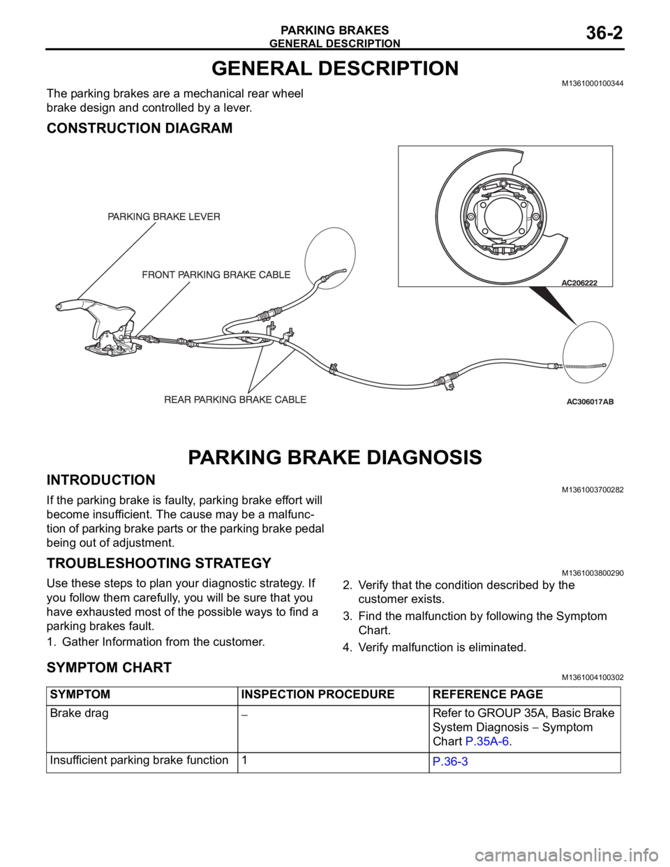
The parking brakes are a mechanical rear wheel
brake design and controlled by a lever.
CONSTRUCTION DIAGRAM
PARKING BRAKE DIAGNOSIS
INTRODUCTIONM1361003700282
If the parking brake is faulty, parking brake effort will
become insufficient. The cause may be a malfunc-
tion of parking brake parts or the parking brake pedal
being out of adjustment.
TROUBLESHOOTING STRATEGYM1361003800290
Use these steps to plan your diagnostic strategy. If
you follow them carefully, you will be sure that you
have exhausted most of the possible ways to find a
parking brakes fault.
1. Gather Information from the customer.2. Verify that the condition described by the
customer exists.
3. Find the malfunction by following the Symptom
Chart.
4. Verify malfunction is eliminated.
SYMPTOM CHARTM1361004100302
SYMPTOM INSPECTION PROCEDURE REFERENCE PAGE
Brake drag
Refer to GROUP 35A, Basic Brake
System Diagnosis
Symptom
Chart P.35A-6.
Insufficient parking brake function 1
P.36-3
Page 1211 of 1500

ON-VEHICLE SERVICE
PARKING BRAKES36-4
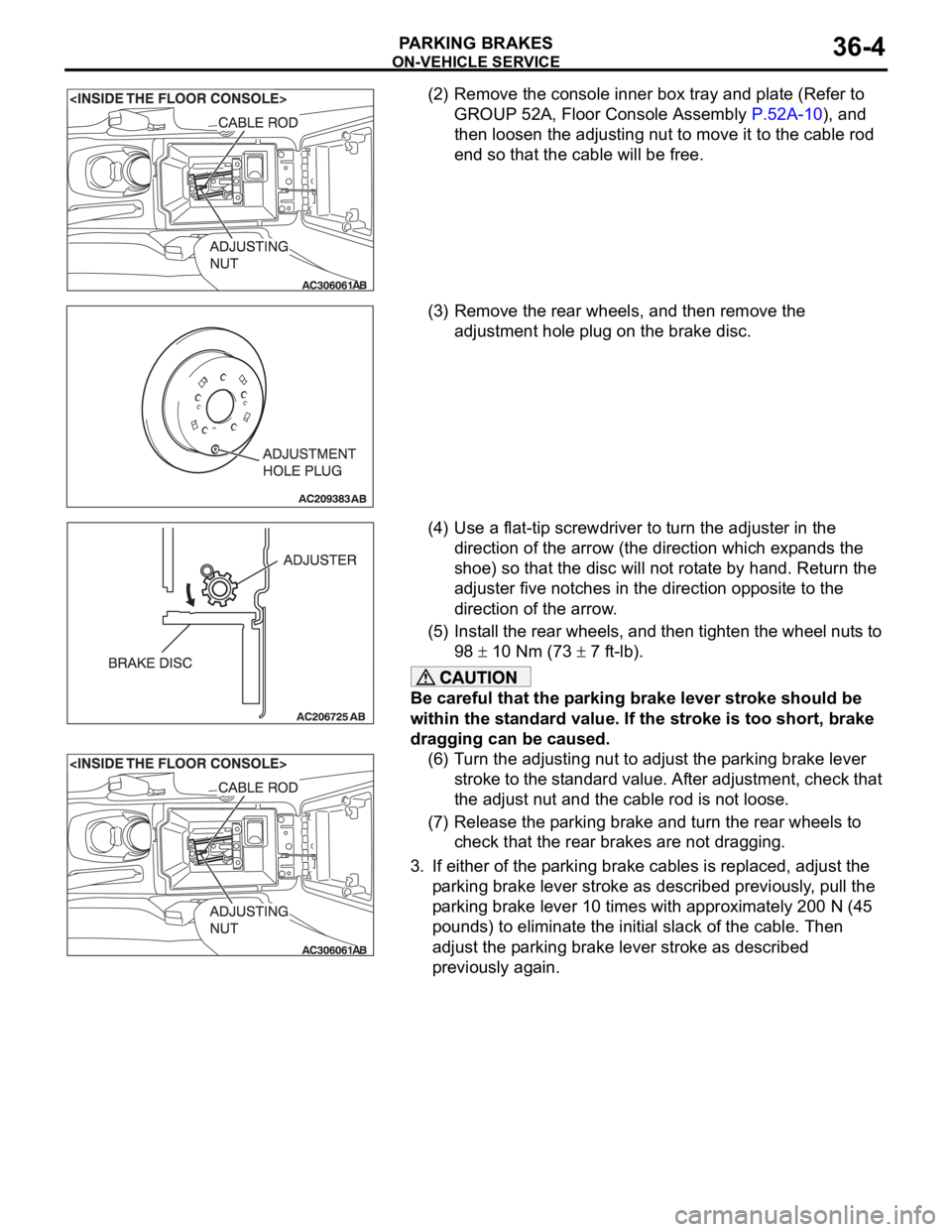
(2) Remove the console inner box tray and plate (Refer to
GROUP 52A, Floor Console Assembly P.52A-10), and
then loosen the adjusting nut to move it to the cable rod
end so that the cable will be free.
(3) Remove the rear wheels, and then remove the
adjustment hole plug on the brake disc.
(4) Use a flat-tip screwdriver to turn the adjuster in the
direction of the arrow (the direction which expands the
shoe) so that the disc will not rotate by hand. Return the
adjuster five notches in the direction opposite to the
direction of the arrow.
(5) Install the rear wheels, and then tighten the wheel nuts to
98
10 Nm (73 7 ft-lb).
Be careful that the parking brake lever stroke should be
within the standard value. If the stroke is too short, brake
dragging can be caused.
(6) Turn the adjusting nut to adjust the parking brake lever
stroke to the standard value. After adjustment, check that
the adjust nut and the cable rod is not loose.
(7) Release the parking brake and turn the rear wheels to
check that the rear brakes are not dragging.
3. If either of the parking brake cables is replaced, adjust the
parking brake lever stroke as described previously, pull the
parking brake lever 10 times with approximately 200 N (45
pounds) to eliminate the initial slack of the cable. Then
adjust the parking brake lever stroke as described
previously again.
Page 1215 of 1500
Page 1216 of 1500
Page 1219 of 1500
SPECIFICATIONS
PARKING BRAKES36-12
SPECIFICATIONS
FASTENER TIGHTENING SPECIFICATIONSM1361003500266
SERVICE SPECIFICATIONSM1361000300412
LUBRICANTM1361000400301
ITEM SPECIFICATION
Parking brake lining and drum
Rear brake bolt (rear brake caliper assembly mounting
bolt)60
5 Nm (45 3 ft-lb)
Rear wheel hub assembly mounting bolt 73
7 Nm (54 5 ft-lb)
ITEMS STANDARD VALUE LIMIT
Parking brake lever stroke
[Parking brake lever pull force: Approximately 200 N
(45 pounds)]5
7 notches
Rear brake lining thickness mm (in) 2.8 Minimum 1.0
Brake drum inside diameter mm (in) 190.0 191.0
ITEM SPECIFIED LUBRICANT
Rear brake shoe slack adjuster Brake grease SAE J310, NLGI No.1
Backing plate
Rear brake shoe assembly