2005 MERCEDES-BENZ SPRINTER oil pressure
[x] Cancel search: oil pressurePage 799 of 1232
(8) Position and install the oil pan. Tighten M6
bolts to 9 N´m (80 lbs in) and M8 bolts to 20 N´m
(177 lbs in).
(9) Install belt /pulley vibration damper. Tighten
M8.8 bolt in two stages, 200N´m (147 lbs ft.) then
90É, M10.9 bolt 325N´m (240 lbs ft) then 90É.
(10) Remove the engine support fixture.
(11) Install generator (Refer to 8 - ELECTRICAL/
CHARGING/GENERATOR - INSTALLATION).
(12) Install the air conditioning compressor.
(13) Install the power steering pump.
(14) Install water pump (Refer to 7 - COOLING/
ENGINE/WATER PUMP - INSTALLATION).
(15) Connect coolant hose to oil-water heat
exchanger.
(16) Install high pressure fuel pump (Refer to 14 -
FUEL SYSTEM/FUEL DELIVERY/FUEL PUMP -
INSTALLATION).
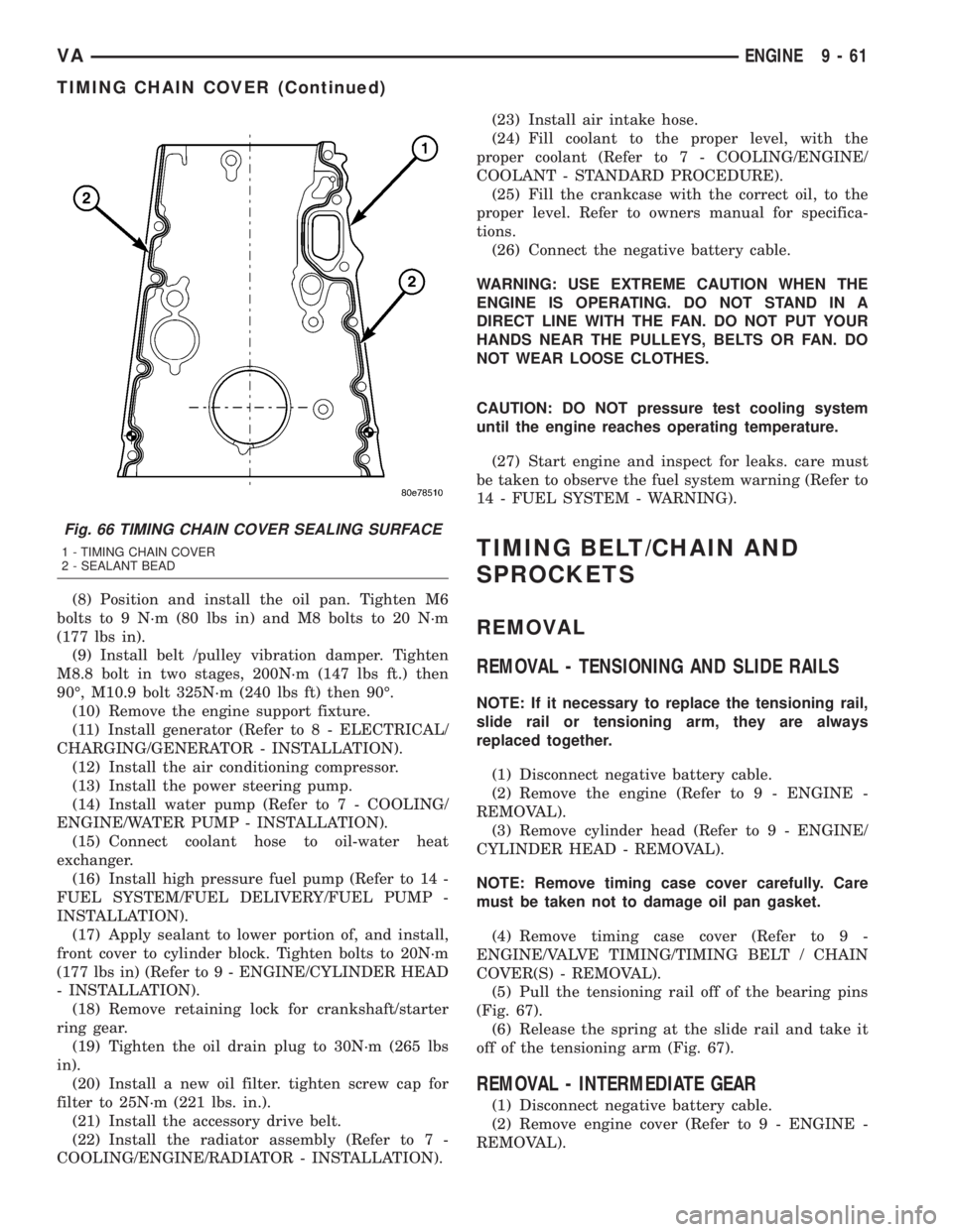
(17) Apply sealant to lower portion of, and install,
front cover to cylinder block. Tighten bolts to 20N´m
(177 lbs in) (Refer to 9 - ENGINE/CYLINDER HEAD
- INSTALLATION).
(18) Remove retaining lock for crankshaft/starter
ring gear.
(19) Tighten the oil drain plug to 30N´m (265 lbs
in).
(20) Install a new oil filter. tighten screw cap for
filter to 25N´m (221 lbs. in.).
(21) Install the accessory drive belt.
(22) Install the radiator assembly (Refer to 7 -
COOLING/ENGINE/RADIATOR - INSTALLATION).(23) Install air intake hose.
(24) Fill coolant to the proper level, with the
proper coolant (Refer to 7 - COOLING/ENGINE/
COOLANT - STANDARD PROCEDURE).
(25) Fill the crankcase with the correct oil, to the
proper level. Refer to owners manual for specifica-
tions.
(26) Connect the negative battery cable.
WARNING: USE EXTREME CAUTION WHEN THE
ENGINE IS OPERATING. DO NOT STAND IN A
DIRECT LINE WITH THE FAN. DO NOT PUT YOUR
HANDS NEAR THE PULLEYS, BELTS OR FAN. DO
NOT WEAR LOOSE CLOTHES.
CAUTION: DO NOT pressure test cooling system
until the engine reaches operating temperature.
(27) Start engine and inspect for leaks. care must
be taken to observe the fuel system warning (Refer to
14 - FUEL SYSTEM - WARNING).
TIMING BELT/CHAIN AND
SPROCKETS
REMOVAL
REMOVAL - TENSIONING AND SLIDE RAILS
NOTE: If it necessary to replace the tensioning rail,
slide rail or tensioning arm, they are always
replaced together.
(1) Disconnect negative battery cable.
(2) Remove the engine (Refer to 9 - ENGINE -
REMOVAL).
(3) Remove cylinder head (Refer to 9 - ENGINE/
CYLINDER HEAD - REMOVAL).
NOTE: Remove timing case cover carefully. Care
must be taken not to damage oil pan gasket.
(4) Remove timing case cover (Refer to 9 -
ENGINE/VALVE TIMING/TIMING BELT / CHAIN
COVER(S) - REMOVAL).
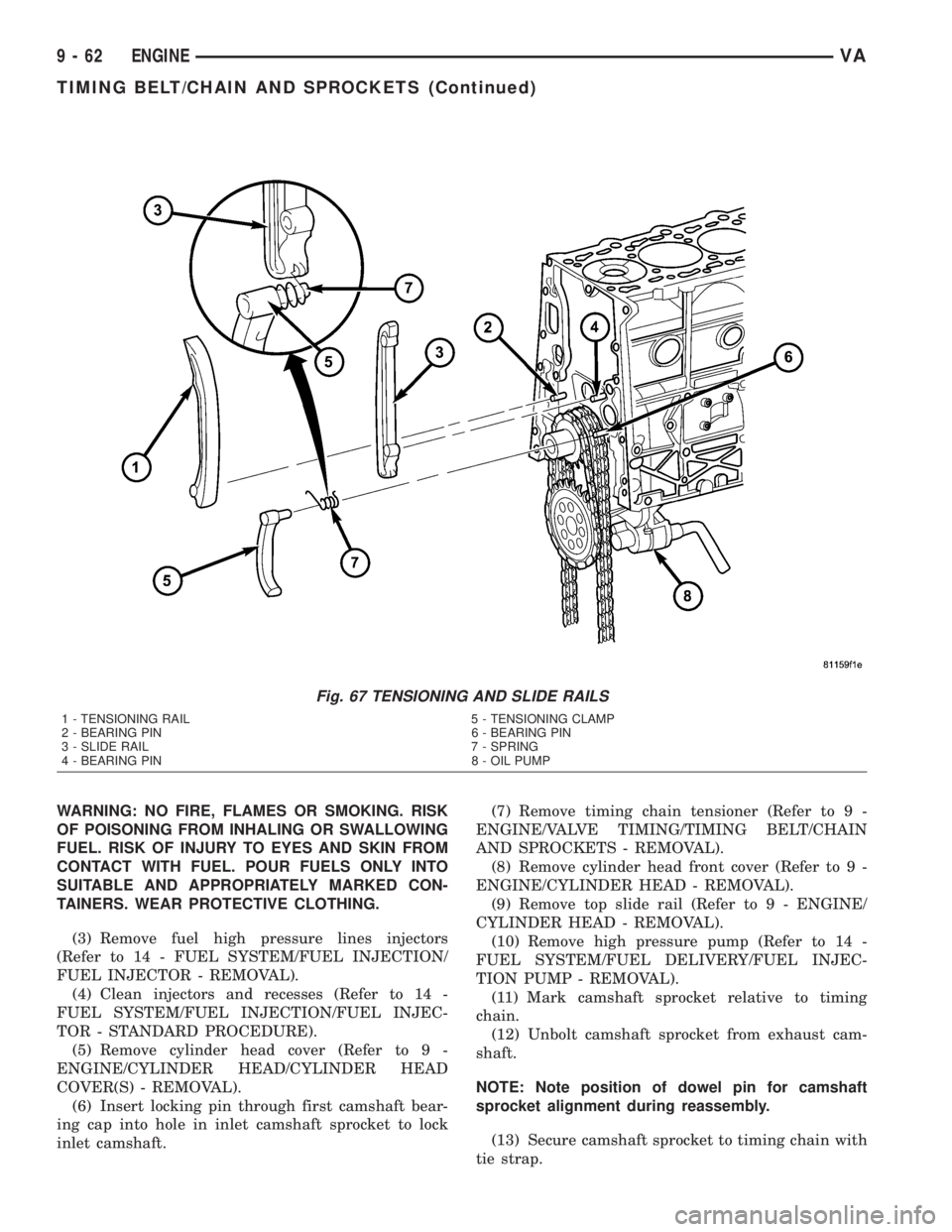
(5) Pull the tensioning rail off of the bearing pins
(Fig. 67).
(6) Release the spring at the slide rail and take it
off of the tensioning arm (Fig. 67).
REMOVAL - INTERMEDIATE GEAR
(1) Disconnect negative battery cable.
(2) Remove engine cover (Refer to 9 - ENGINE -
REMOVAL).
Fig. 66 TIMING CHAIN COVER SEALING SURFACE
1 - TIMING CHAIN COVER
2 - SEALANT BEAD
VAENGINE 9 - 61
TIMING CHAIN COVER (Continued)
Page 800 of 1232
WARNING: NO FIRE, FLAMES OR SMOKING. RISK
OF POISONING FROM INHALING OR SWALLOWING
FUEL. RISK OF INJURY TO EYES AND SKIN FROM
CONTACT WITH FUEL. POUR FUELS ONLY INTO
SUITABLE AND APPROPRIATELY MARKED CON-
TAINERS. WEAR PROTECTIVE CLOTHING.
(3) Remove fuel high pressure lines injectors
(Refer to 14 - FUEL SYSTEM/FUEL INJECTION/
FUEL INJECTOR - REMOVAL).
(4) Clean injectors and recesses (Refer to 14 -
FUEL SYSTEM/FUEL INJECTION/FUEL INJEC-
TOR - STANDARD PROCEDURE).
(5) Remove cylinder head cover (Refer to 9 -
ENGINE/CYLINDER HEAD/CYLINDER HEAD
COVER(S) - REMOVAL).
(6) Insert locking pin through first camshaft bear-
ing cap into hole in inlet camshaft sprocket to lock
inlet camshaft.(7) Remove timing chain tensioner (Refer to 9 -
ENGINE/VALVE TIMING/TIMING BELT/CHAIN
AND SPROCKETS - REMOVAL).
(8) Remove cylinder head front cover (Refer to 9 -
ENGINE/CYLINDER HEAD - REMOVAL).
(9) Remove top slide rail (Refer to 9 - ENGINE/
CYLINDER HEAD - REMOVAL).
(10) Remove high pressure pump (Refer to 14 -
FUEL SYSTEM/FUEL DELIVERY/FUEL INJEC-
TION PUMP - REMOVAL).
(11) Mark camshaft sprocket relative to timing
chain.
(12) Unbolt camshaft sprocket from exhaust cam-
shaft.
NOTE: Note position of dowel pin for camshaft
sprocket alignment during reassembly.
(13) Secure camshaft sprocket to timing chain with
tie strap.
Fig. 67 TENSIONING AND SLIDE RAILS
1 - TENSIONING RAIL 5 - TENSIONING CLAMP
2 - BEARING PIN 6 - BEARING PIN
3 - SLIDE RAIL 7 - SPRING
4 - BEARING PIN 8 - OIL PUMP
9 - 62 ENGINEVA
TIMING BELT/CHAIN AND SPROCKETS (Continued)
Page 801 of 1232
(14) Remove camshaft sprocket.
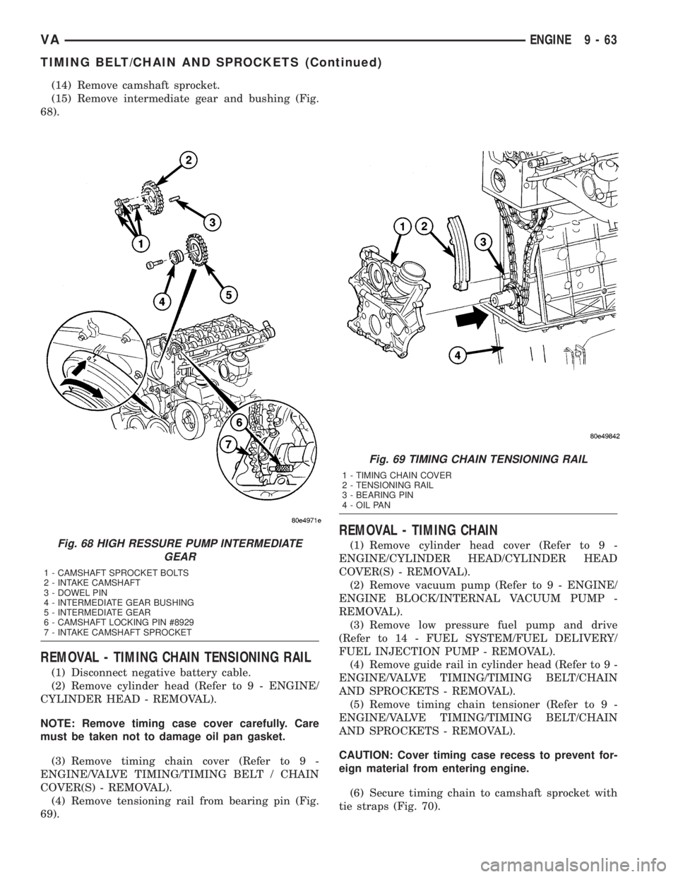
(15) Remove intermediate gear and bushing (Fig.
68).
REMOVAL - TIMING CHAIN TENSIONING RAIL
(1) Disconnect negative battery cable.
(2) Remove cylinder head (Refer to 9 - ENGINE/
CYLINDER HEAD - REMOVAL).
NOTE: Remove timing case cover carefully. Care
must be taken not to damage oil pan gasket.
(3) Remove timing chain cover (Refer to 9 -
ENGINE/VALVE TIMING/TIMING BELT / CHAIN
COVER(S) - REMOVAL).
(4) Remove tensioning rail from bearing pin (Fig.
69).
REMOVAL - TIMING CHAIN
(1) Remove cylinder head cover (Refer to 9 -
ENGINE/CYLINDER HEAD/CYLINDER HEAD
COVER(S) - REMOVAL).
(2) Remove vacuum pump (Refer to 9 - ENGINE/
ENGINE BLOCK/INTERNAL VACUUM PUMP -
REMOVAL).
(3) Remove low pressure fuel pump and drive
(Refer to 14 - FUEL SYSTEM/FUEL DELIVERY/
FUEL INJECTION PUMP - REMOVAL).
(4) Remove guide rail in cylinder head (Refer to 9 -
ENGINE/VALVE TIMING/TIMING BELT/CHAIN
AND SPROCKETS - REMOVAL).
(5) Remove timing chain tensioner (Refer to 9 -
ENGINE/VALVE TIMING/TIMING BELT/CHAIN
AND SPROCKETS - REMOVAL).
CAUTION: Cover timing case recess to prevent for-
eign material from entering engine.
(6) Secure timing chain to camshaft sprocket with
tie straps (Fig. 70).Fig. 68 HIGH RESSURE PUMP INTERMEDIATE
GEAR
1 - CAMSHAFT SPROCKET BOLTS
2 - INTAKE CAMSHAFT
3 - DOWEL PIN
4 - INTERMEDIATE GEAR BUSHING
5 - INTERMEDIATE GEAR
6 - CAMSHAFT LOCKING PIN #8929
7 - INTAKE CAMSHAFT SPROCKET
Fig. 69 TIMING CHAIN TENSIONING RAIL
1 - TIMING CHAIN COVER
2 - TENSIONING RAIL
3 - BEARING PIN
4 - OIL PAN
VAENGINE 9 - 63
TIMING BELT/CHAIN AND SPROCKETS (Continued)
Page 804 of 1232
CAUTION: IT IS ESSENTIAL that the installation pro-
cedure for the timing chain is followed exactly. Fail-
ure to do so will result in severe engine damage.
INSTALLATION
INSTALLATION - TENSIONING AND SLIDE RAIL
NOTE: Carefully clean all mating surfaces with
appropriate solvents to assure that no grease or oil
is present during reassembly.
CAUTION: ENSURE THAT THE SPRING IS COR-
RECTLY INSTALLED ON THE TENSIONING CLAMP
AND SLIDE RAIL.
(1) Install rail on bearing pin (Fig. 67).
(2) Install timing cover (Refer to 9 - ENGINE/
VALVE TIMING/TIMING BELT / CHAIN COVER(S)
- INSTALLATION).
(3) Install oil pan bolts. Tighten M6 bolts to 9N´m
(80 lbs.in.) and M8 bolts to 20N´m (15 lbs. ft.).
(4) Install cylinder head (Refer to 9 - ENGINE/
CYLINDER HEAD - INSTALLATION).
(5) Install the engine.
(6) Reconnect negative battery cable.
WARNING: USE EXTREME CAUTION WHEN THE
ENGINE IS OPERATING. DO NOT STAND IN A
DIRECT LINE WITH THE FAN. DO NOT PUT YOUR
HANDS NEAR THE PULLEYS, BELTS OR FAN. DO
NOT WEAR LOOSE CLOTHES.
(7) Start the engine and inspect for leaks. care
must be take to observe the fuel system warning
(Refer to 14 - FUEL SYSTEM - WARNING).
INSTALLATION - INTERMEDIATE GEAR
NOTE: Refer to appropriate injector servicing proce-
dures for cleaning of injectors and recesses.
(1) Install intermediate gear and bushing. Tighten
bolt to 40N´m (30 lbs.ft.)
(2) Install camshaft sprocket, noting dowel pin
alignment. Tighten bolt to 18 N´m (159 lbs. in.).
(3) Remove tie strap retaining timing chain to
sprocket.
WARNING: NO FIRE, FLAMES OR SMOKING. SER-
VICE VEHICLE IN WELL VENTILATED AREA. RISK
OF INJURY FROM INHALING OR SWALLOWING
FUEL. RISK OF INJURY TO EYES AND SKIN FROM
CONTACT WITH FUEL. WEAR PROTECTIVE CLOTH-
ING.(4) Install high pressure pump (Refer to 14 -
FUEL SYSTEM/FUEL DELIVERY/FUEL INJEC-
TION PUMP - INSTALLATION).
(5) Install top slide rail (Refer to 9 - ENGINE/
VALVE TIMING/TIMING BELT/CHAIN AND
SPROCKETS - INSTALLATION).
(6) Install cylinder head front cover (Refer to 9 -
ENGINE/CYLINDER HEAD - INSTALLATION).
(7) Install timing chain tensioner with new gasket
(Refer to 9 - ENGINE/VALVE TIMING/TIMING
BELT/CHAIN AND SPROCKETS - INSTALLA-
TION).
NOTE: Inspect basic position of camshaft and reset
if necessary.
(8) Remove camshaft locking pin.
(9) Install cylinder head cover (Refer to 9 -
ENGINE/CYLINDER HEAD/CYLINDER HEAD
COVER(S) - INSTALLATION).
WARNING: NO FIRE, FLAMES OR SMOKING. SER-
VICE VEHICLE IN WELL VENTILATED AREA. RISK
OF INJURY FROM INHALING OR SWALLOWING
FUEL. RISK OF INJURY TO EYES AND SKIN FROM
CONTACT WITH FUEL. WEAR PROTECTIVE CLOTH-
ING.
(10) Install fuel high pressure lines and injectors
(Refer to 14 - FUEL SYSTEM/FUEL INJECTION/
FUEL INJECTOR - INSTALLATION).
(11) Install engine cover (Refer to 9 - ENGINE -
INSTALLATION).
(12) Connect negative battery cable.
WARNING: USE EXTREME CAUTION WHEN THE
ENGINE IS OPERATING. DO NOT STAND IN A
DIRECT LINE WITH FAN. DO NOT PUT YOUR
HANDS NEAR THE PULLEYS, BELTS OR FAN. DO
NOT WEAR LOOSE CLOTHING.
(13) Start engine and inspect for leaks. Care must
be taken to observe the fuel system warning (Refer to
14 - FUEL SYSTEM - WARNING).
INSTALLATION - TIMING CHAIN TENSIONING
RAIL
NOTE: Carefully clean all mating surfaces with
appropriate solvents to assure that no grease or oil
is present during reassembly.
(1) Install tensioning rail on bearing pin
(2) Install timing cover (Refer to 9 - ENGINE/
VALVE TIMING/TIMING BELT / CHAIN COVER(S)
- INSTALLATION).
9 - 66 ENGINEVA
TIMING BELT/CHAIN AND SPROCKETS (Continued)
Page 805 of 1232
(3) Install oil pan and bolts. Tighten M6 bolts to
9N´m (80 lbs.in.) and M8 bolts to 20N´m (15 lbs. ft.).
(4) Install cylinder head (Refer to 9 - ENGINE/
CYLINDER HEAD - INSTALLATION).
(5) Reconnect negative battery cable.
WARNING: USE EXTREME CAUTION WHEN THE
ENGINE IS OPERATING. DO NOT PUT YOUR
HANDS NEAR THE PULLEYS, BELTS OR FAN. DO
NOT WEAR LOOSE CLOTHES.
(6) Start the engine and inspect for leaks. Care
must be taken to observe the fuel system warning
(Refer to 14 - FUEL SYSTEM - WARNING).
ADJUSTMENTS
INSTALLATION - TIMING CHAIN
CAUTION: IT IS ESSENTIAL that the installation pro-
cedure is followed exactly. Failure to do so will
result in severe engine damage.CAUTION: Cover timing case recesses to prevent
foreign material from entering engine.
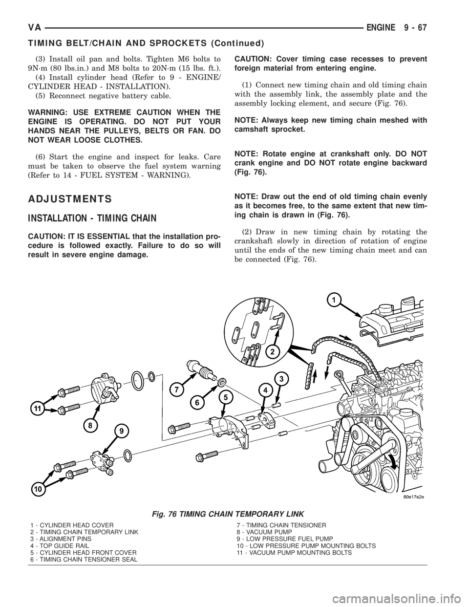
(1) Connect new timing chain and old timing chain
with the assembly link, the assembly plate and the
assembly locking element, and secure (Fig. 76).
NOTE: Always keep new timing chain meshed with
camshaft sprocket.
NOTE: Rotate engine at crankshaft only. DO NOT
crank engine and DO NOT rotate engine backward
(Fig. 76).
NOTE: Draw out the end of old timing chain evenly
as it becomes free, to the same extent that new tim-
ing chain is drawn in (Fig. 76).
(2) Draw in new timing chain by rotating the
crankshaft slowly in direction of rotation of engine
until the ends of the new timing chain meet and can
be connected (Fig. 76).
Fig. 76 TIMING CHAIN TEMPORARY LINK
1 - CYLINDER HEAD COVER
2 - TIMING CHAIN TEMPORARY LINK
3 - ALIGNMENT PINS
4 - TOP GUIDE RAIL
5 - CYLINDER HEAD FRONT COVER
6 - TIMING CHAIN TENSIONER SEAL7 - TIMING CHAIN TENSIONER
8 - VACUUM PUMP
9 - LOW PRESSURE FUEL PUMP
10 - LOW PRESSURE PUMP MOUNTING BOLTS
11 - VACUUM PUMP MOUNTING BOLTS
VAENGINE 9 - 67
TIMING BELT/CHAIN AND SPROCKETS (Continued)
Page 814 of 1232
²Higher torque as a result of improved cylinder
charge.
²Reduction in exhaust emissions as a result of an
improvement in the air supply of the engine.
²Increased power output as a result of the higher
charge pressure combined with a reduced exhaust
backpressure and thus improved charge cycle.
OPERATION
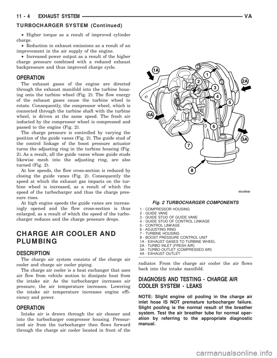
The exhaust gases of the engine are directed
through the exhaust manifold into the turbine hous-
ing onto the turbine wheel (Fig. 2). The flow energy
of the exhaust gases cause the turbine wheel to
rotate. Consequently, the compressor wheel, which is
connected through the turbine shaft with the turbine
wheel, is driven at the same speed. The fresh air
inducted by the compressor wheel is compressed and
passed to the engine (Fig. 2).
The charge pressure is controlled by varying the
position of the guide vanes (Fig. 2). The guide stud of
the control linkage of the boost pressure actuator
turns the adjusting ring in the turbine housing (Fig.
2). As a result, all the guide vanes whose guide studs
likewise mesh into the adjusting ring, are also
turned (Fig. 2).
At low speeds, the flow cross-section is reduced by
closing the guide vanes (Fig. 2). Consequently the
speed at which the exhaust gas impacts on the tur-
bine wheel is increased, as a result of which the
speed of the turbocharger and thus the charge pres-
sure rises.
At high engine speeds the guide vanes are increas-
ingly opened and the flow cross-section is thus
enlarged, as a result of which the speed of the turbo-
charger reduces and the charge pressure drops.
CHARGE AIR COOLER AND
PLUMBING
DESCRIPTION
The charge air system consists of the charge air
cooler and charge air cooler piping.
The charge air cooler is a heat exchanger that uses
air flow from vehicle motion to dissipate heat from
the intake air. As the turbocharger increases air
pressure, the air temperature increases. Lowering
the intake air temperature increases engine effi-
ciency and power.
OPERATION
Intake air is drawn through the air cleaner and
into the turbocharger compressor housing. Pressur-
ized air from the turbocharger then flows forward
through the charge air cooler located in front of theradiator. From the charge air cooler the air flows
back into the intake manifold.
DIAGNOSIS AND TESTING - CHARGE AIR
COOLER SYSTEM - LEAKS
NOTE: Slight engine oil pooling in the charge air
inlet hose IS NOT premature turbocharger failure.
Slight pooling is the normal result of the breather
system. Test the air breather tube for normal oper-
ation by referring to the appropriate diagnostic
manual.
Fig. 2 TURBOCHARGER COMPONENTS
1 - COMPRESSOR HOUSING
2 - GUIDE VANE
3 - GUIDE STUD OF GUIDE VANE
4 - GUIDE STUD OF CONTROL LINKAGE
5 - CONTROL LINKAGE
6 - ADJUSTING RING
7 - TURBINE HOUSING
8 - BOOST PRESSURE CONTROL UNIT
1A - EXHAUST GASES TO TURBINE WHEEL
2A - TURBO INLET (FRESH AIR)
3A - TURBO OUTLET (COMPRESSED AIR)
4A - EXHAUST OUTLET
11 - 4 EXHAUST SYSTEMVA
TURBOCHARGER SYSTEM (Continued)
Page 815 of 1232
Low turbocharger boost pressure and low engine
performance can be caused by leaks in the charge air
cooler or it's plumbing. The following procedure out-
lines how to check for leaks in the charge air cooler
system.
(1) Loosen clamp and remove turbocharger to air
inlet duct rubber sleeve from turbocharger.
(2) Insert Special Tool 8442 Adapter into the rub-
ber sleeve. Tighten existing clamp to 8 N´m (72
in.lbs.).
CAUTION: Do not apply more than 138 kpa (20 psi)
air pressure to the charge air cooler system, sever
damage to the charge air cooler system may occur.
(3) Connect regulated air supply to air fitting on
Special Tool 8442 Adapter. Set air pressure to a Max-
imum of 138 kpa (20 psi).
(4) Using soapy water check the air inlet ducts,
rubber sleeves, charge air cooler and intake manifold
for leaks.
REMOVAL
(1) Remove front bumper.
(2) Remove headlamp assemblies.
(3) Remove front cross member together with front
grille.
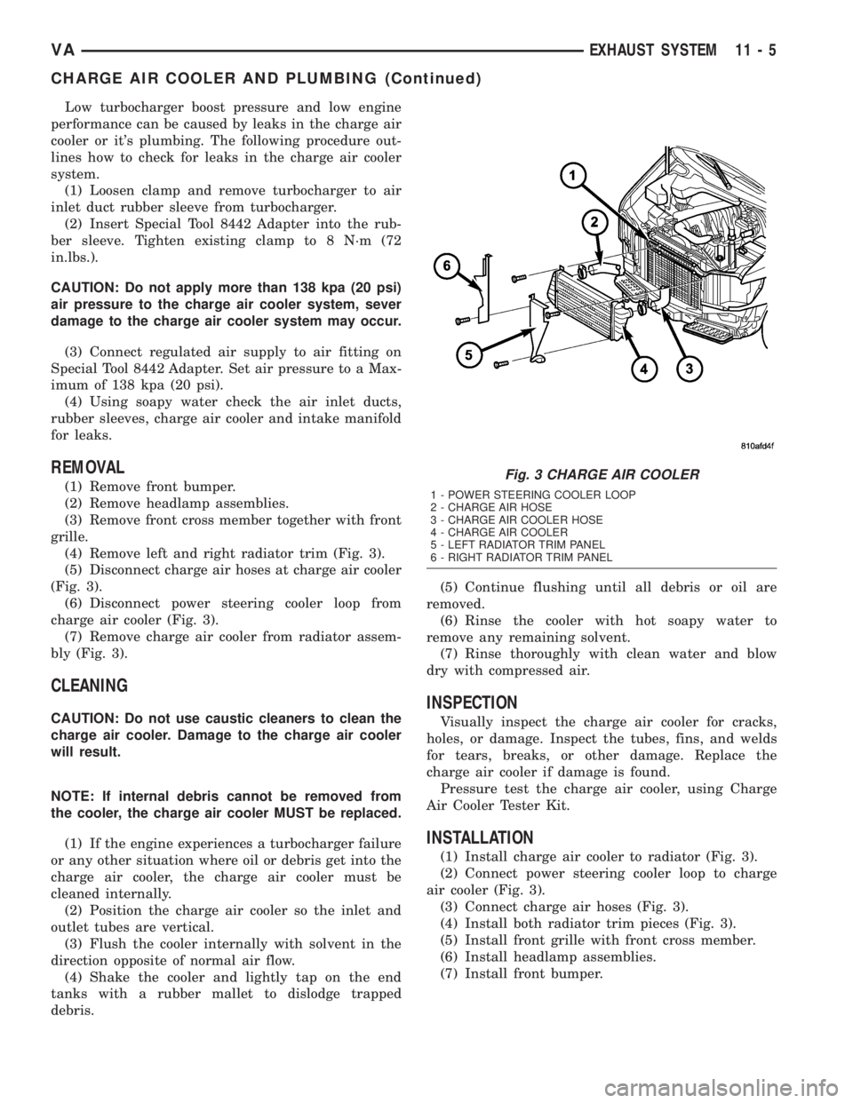
(4) Remove left and right radiator trim (Fig. 3).
(5) Disconnect charge air hoses at charge air cooler
(Fig. 3).
(6) Disconnect power steering cooler loop from
charge air cooler (Fig. 3).
(7) Remove charge air cooler from radiator assem-
bly (Fig. 3).
CLEANING
CAUTION: Do not use caustic cleaners to clean the
charge air cooler. Damage to the charge air cooler
will result.
NOTE: If internal debris cannot be removed from
the cooler, the charge air cooler MUST be replaced.
(1) If the engine experiences a turbocharger failure
or any other situation where oil or debris get into the
charge air cooler, the charge air cooler must be
cleaned internally.
(2) Position the charge air cooler so the inlet and
outlet tubes are vertical.
(3) Flush the cooler internally with solvent in the
direction opposite of normal air flow.
(4) Shake the cooler and lightly tap on the end
tanks with a rubber mallet to dislodge trapped
debris.(5) Continue flushing until all debris or oil are
removed.
(6) Rinse the cooler with hot soapy water to
remove any remaining solvent.
(7) Rinse thoroughly with clean water and blow
dry with compressed air.
INSPECTION
Visually inspect the charge air cooler for cracks,
holes, or damage. Inspect the tubes, fins, and welds
for tears, breaks, or other damage. Replace the
charge air cooler if damage is found.
Pressure test the charge air cooler, using Charge
Air Cooler Tester Kit.
INSTALLATION
(1) Install charge air cooler to radiator (Fig. 3).
(2) Connect power steering cooler loop to charge
air cooler (Fig. 3).
(3) Connect charge air hoses (Fig. 3).
(4) Install both radiator trim pieces (Fig. 3).
(5) Install front grille with front cross member.
(6) Install headlamp assemblies.
(7) Install front bumper.
Fig. 3 CHARGE AIR COOLER
1 - POWER STEERING COOLER LOOP
2 - CHARGE AIR HOSE
3 - CHARGE AIR COOLER HOSE
4 - CHARGE AIR COOLER
5 - LEFT RADIATOR TRIM PANEL
6 - RIGHT RADIATOR TRIM PANEL
VAEXHAUST SYSTEM 11 - 5
CHARGE AIR COOLER AND PLUMBING (Continued)
Page 830 of 1232
DIAGNOSIS AND TESTING - AIR IN FUEL
SYSTEM
Air will enter the fuel system whenever fuel supply
lines, separator filters, injection pump, high-pressure
lines or injectors are removed or disconnected. Air
trapped in the fuel system can result in hard start-
ing, a rough running engine, engine misfire, low
power, excessive smoke and fuel knock.
Inspect the fuel system from the fuel tank to the
injectors for loose connections (Refer to 14 - FUEL
SYSTEM - WARNING). Leaking fuel is an indicator
of loose connections or defective seals. Air can also
enter the fuel system between the fuel tank and the
fuel pump. Inspect the fuel tank and fuel lines for
damage that might allow air into the system.
With the DRBIIItconnected to the vehicle, select
Engine and the select Sensor Display. Page down to
view Fuel Pressure Set Point and Actual Fuel Pres-
sure. Start the engine and observe the Fuel Pressure
Set Point and the Actual Fuel Pressure. If the Actual
Fuel Pressure Oscillates above and below the Fuel
Pressure Set Point in a regular cycle, perform the
Fuel System Air Purge procedure (Refer to 14 -
FUEL SYSTEM - STANDARD PROCEDURE).
If the Actual Fuel Pressure gradually drops below
the Fuel Pressure Set Point then spikes well above
the Fuel Pressure Set Point, replace the fuel pres-
sure solenoid (Refer to 14 - FUEL SYSTEM/FUEL
INJECTION/FUEL PRESSURE SOLENOID -
REMOVAL), then perform the Fuel System Air Purgeprocedure (Refer to 14 - FUEL SYSTEM - STAN-
DARD PROCEDURE).
STANDARD PROCEDURE
STANDARD PROCEDURES - CLEANING FUEL
SYSTEM COMPONENTS
CAUTION: Cleanliness cannot be overemphasized
when handling or replacing diesel fuel system com-
ponents. This especially includes the fuel injectors,
high-pressure fuel lines, fuel rail, and fuel injection
pump. Very tight tolerances are used with these
parts. Dirt contamination could cause rapid part
wear and possible plugging of fuel injector nozzle
tip holes. This in turn could lead to possible engine
misfire. Always wash/clean any fuel system compo-
nent thoroughly before disassembly and then air
dry. DO NOT wire brush injector nozzles when
cleaning. Cap or cover any open part after disas-
sembly. Before assembly, examine each part for
dirt, grease or other contaminants and clean if nec-
essary. When installing new parts, lubricate them
with clean engine oil or clean diesel fuel only.
STANDARD PROCEDURE - DISCONNECTING
AND CONNECTING FUEL LINES
NOTE: Capture and store any fuel spillage in appro-
priately marked containers.
(1) Disconnect negative battery cable.
(2) Push release arm to release position A, as far
as the stop (arrow) (Fig. 2).
(3) Disconnect fuel line.
(4) Immediately return the release arm back to the
assembly position, as far as the stop (Fig. 2).
The release arm must not be left in the release
position for a long time. Connectors left in the
release position for lengthy periods may leak and
must be replaced.
(5) Insert connector into connection in assembly
position (B) (Fig. 2).
(6) Ensure that the connectors are firmly seated
and free of leaks (Fig. 2).
STANDARD PROCEDURES - DRAINING WATER
FROM FUEL FILTER
Refer to Fuel Filter/Water Separator removal/in-
stallation for procedures (Refer to 14 - FUEL SYS-
TEM/FUEL DELIVERY/FUEL FILTER / WATER
SEPARATOR - REMOVAL).
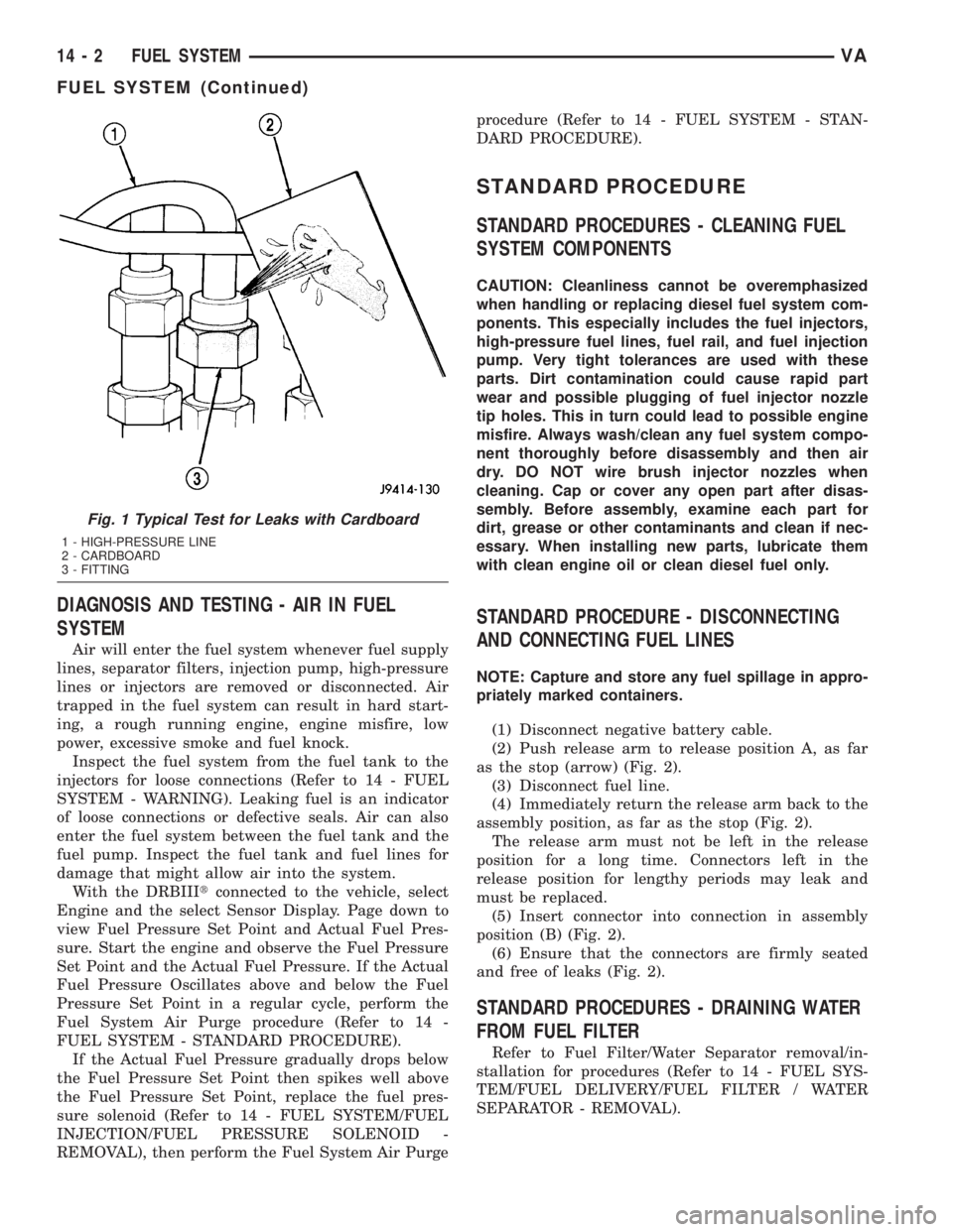
Fig. 1 Typical Test for Leaks with Cardboard
1 - HIGH-PRESSURE LINE
2 - CARDBOARD
3 - FITTING
14 - 2 FUEL SYSTEMVA
FUEL SYSTEM (Continued)