2005 MERCEDES-BENZ SPRINTER oil pressure
[x] Cancel search: oil pressurePage 988 of 1232
OPERATION
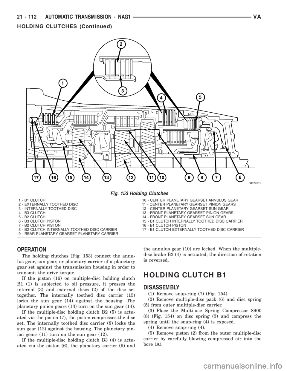
The holding clutches (Fig. 153) connect the annu-
lus gear, sun gear, or planetary carrier of a planetary
gear set against the transmission housing in order to
transmit the drive torque.
If the piston (16) on multiple-disc holding clutch
B1 (1) is subjected to oil pressure, it presses the
internal (3) and external discs (2) of the disc set
together. The internally toothed disc carrier (15)
locks the sun gear (14) against the housing. The
planetary pinion gears (13) turn on the sun gear (14).
If the multiple-disc holding clutch B2 (5) is actu-
ated via the piston (7), the piston compresses the disc
set. The internally toothed disc carrier (8) locks the
sun gear (12) against the housing. The planetary pin-
ion gears (11) turn on the sun gear (12).
If the multiple-disc holding clutch B3 (4) is actu-
ated via the piston (6), the planetary carrier (9) andthe annulus gear (10) are locked. When the multiple-
disc brake B3 (4) is actuated, the direction of rotation
is reversed.
HOLDING CLUTCH B1
DISASSEMBLY
(1) Remove snap-ring (7) (Fig. 154).
(2) Remove multiple-disc pack (6) and disc spring
(5) from outer multiple-disc carrier.
(3) Place the Multi-use Spring Compressor 8900
(8) (Fig. 154) on disc spring (3) and compress the
spring until the snap-ring (4) is exposed.
(4) Remove snap-ring (4).
(5) Remove piston (2) from the outer multiple-disc
carrier by carefully blowing compressed air into the
bore (A).
Fig. 153 Holding Clutches
1 - B1 CLUTCH 10 - CENTER PLANETARY GEARSET ANNULUS GEAR
2 - EXTERNALLY TOOTHED DISC 11 - CENTER PLANETARY GEARSET PINION GEARS
3 - INTERNALLY TOOTHED DISC 12 - CENTER PLANETARY GEARSET SUN GEAR
4 - B3 CLUTCH 13 - FRONT PLANETARY GEARSET PINION GEARS
5 - B2 CLUTCH 14 - FRONT PLANETARY GEARSET SUN GEAR
6 - B3 CLUTCH PISTON 15 - B1 CLUTCH INTERNALLY TOOTHED DISC CARRIER
7 - B2 CLUTCH PISTON 16 - B1 CLUTCH PISTON
8 - B2 CLUTCH INTERNALLY TOOTHED DISC CARRIER 17 - B1 CLUTCH EXTERNALLY TOOTHED DISC CARRIER
9 - REAR PLANETARY GEARSET PLANETARY CARRIER
21 - 112 AUTOMATIC TRANSMISSION - NAG1VA
HOLDING CLUTCHES (Continued)
Page 996 of 1232
OIL PUMP
DESCRIPTION
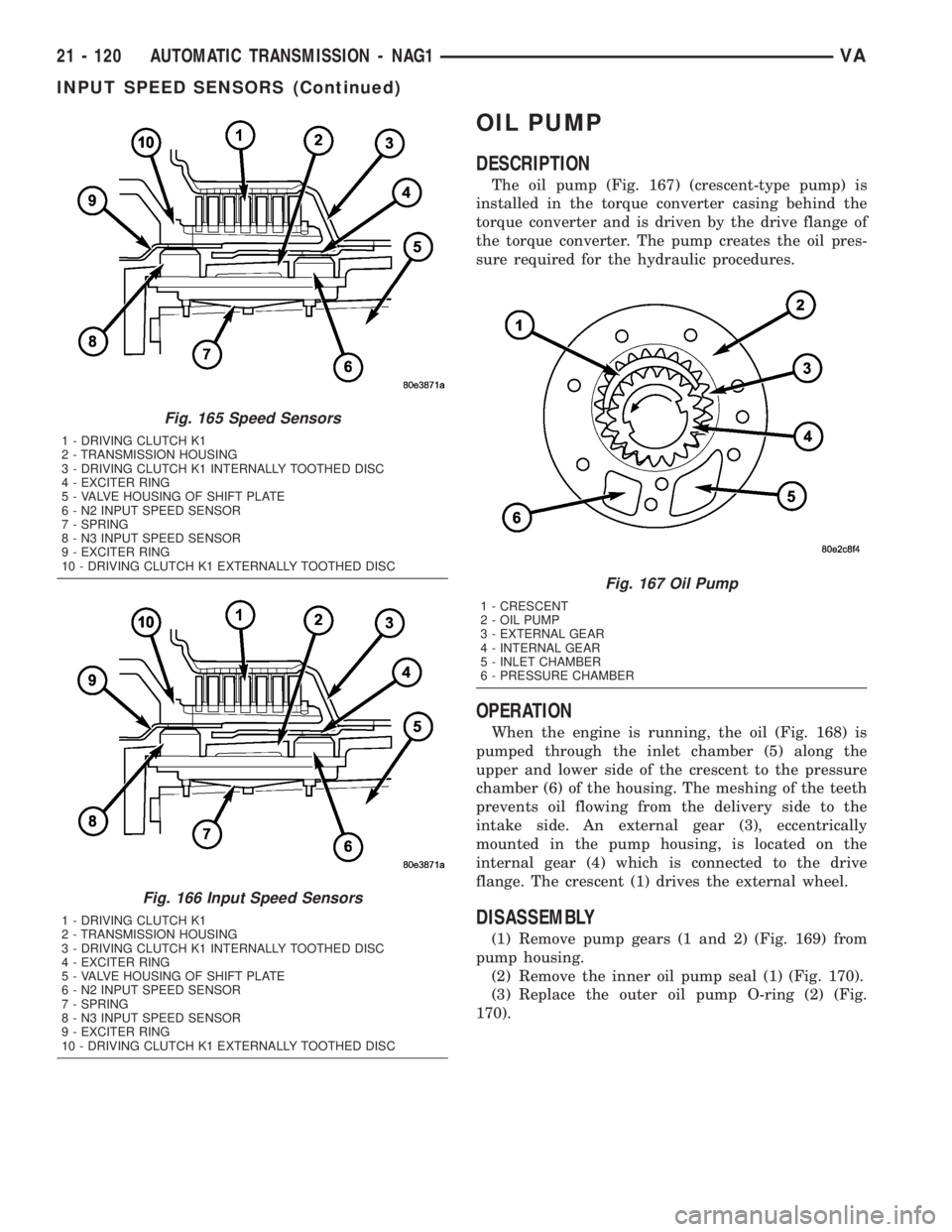
The oil pump (Fig. 167) (crescent-type pump) is
installed in the torque converter casing behind the
torque converter and is driven by the drive flange of
the torque converter. The pump creates the oil pres-
sure required for the hydraulic procedures.
OPERATION
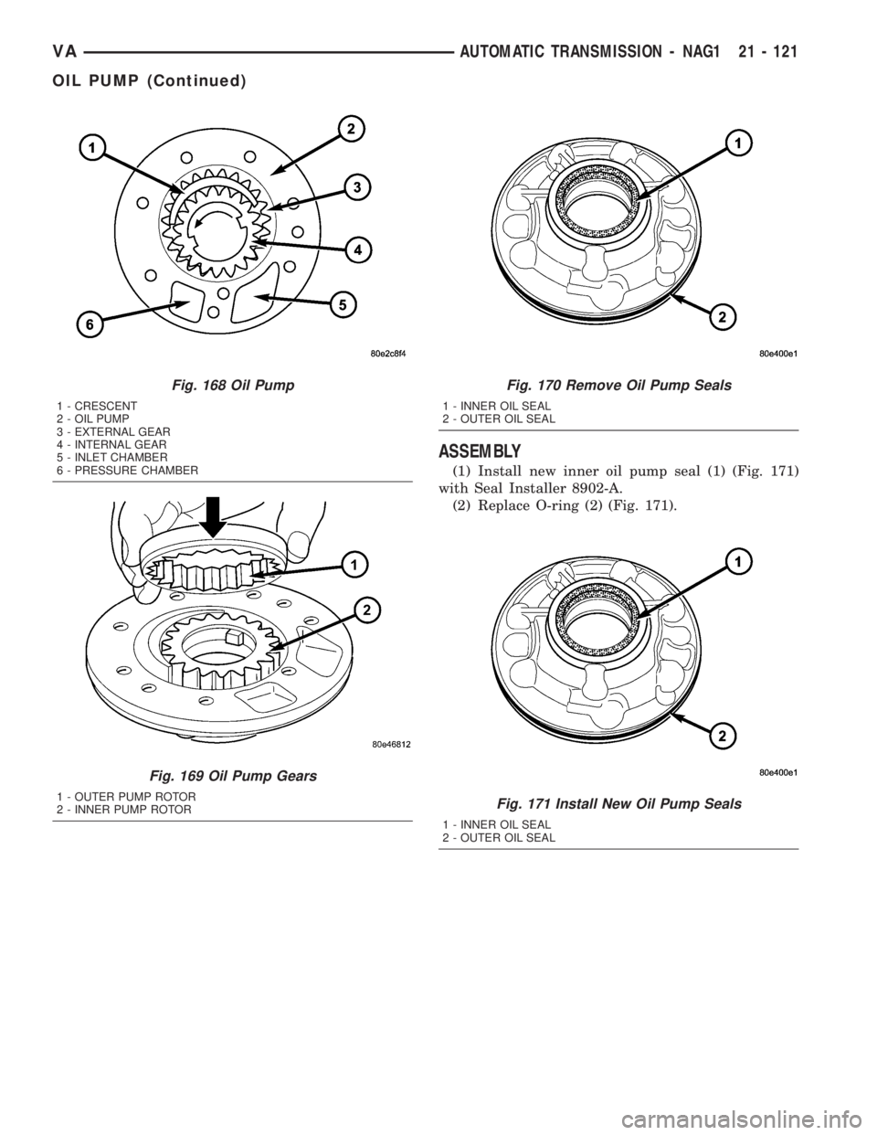
When the engine is running, the oil (Fig. 168) is
pumped through the inlet chamber (5) along the
upper and lower side of the crescent to the pressure
chamber (6) of the housing. The meshing of the teeth
prevents oil flowing from the delivery side to the
intake side. An external gear (3), eccentrically
mounted in the pump housing, is located on the
internal gear (4) which is connected to the drive
flange. The crescent (1) drives the external wheel.
DISASSEMBLY
(1) Remove pump gears (1 and 2) (Fig. 169) from
pump housing.
(2) Remove the inner oil pump seal (1) (Fig. 170).
(3) Replace the outer oil pump O-ring (2) (Fig.
170).
Fig. 165 Speed Sensors
1 - DRIVING CLUTCH K1
2 - TRANSMISSION HOUSING
3 - DRIVING CLUTCH K1 INTERNALLY TOOTHED DISC
4 - EXCITER RING
5 - VALVE HOUSING OF SHIFT PLATE
6 - N2 INPUT SPEED SENSOR
7 - SPRING
8 - N3 INPUT SPEED SENSOR
9 - EXCITER RING
10 - DRIVING CLUTCH K1 EXTERNALLY TOOTHED DISC
Fig. 166 Input Speed Sensors
1 - DRIVING CLUTCH K1
2 - TRANSMISSION HOUSING
3 - DRIVING CLUTCH K1 INTERNALLY TOOTHED DISC
4 - EXCITER RING
5 - VALVE HOUSING OF SHIFT PLATE
6 - N2 INPUT SPEED SENSOR
7 - SPRING
8 - N3 INPUT SPEED SENSOR
9 - EXCITER RING
10 - DRIVING CLUTCH K1 EXTERNALLY TOOTHED DISC
Fig. 167 Oil Pump
1 - CRESCENT
2 - OIL PUMP
3 - EXTERNAL GEAR
4 - INTERNAL GEAR
5 - INLET CHAMBER
6 - PRESSURE CHAMBER
21 - 120 AUTOMATIC TRANSMISSION - NAG1VA
INPUT SPEED SENSORS (Continued)
Page 997 of 1232
ASSEMBLY
(1) Install new inner oil pump seal (1) (Fig. 171)
with Seal Installer 8902-A.
(2) Replace O-ring (2) (Fig. 171).
Fig. 168 Oil Pump
1 - CRESCENT
2 - OIL PUMP
3 - EXTERNAL GEAR
4 - INTERNAL GEAR
5 - INLET CHAMBER
6 - PRESSURE CHAMBER
Fig. 169 Oil Pump Gears
1 - OUTER PUMP ROTOR
2 - INNER PUMP ROTOR
Fig. 170 Remove Oil Pump Seals
1 - INNER OIL SEAL
2 - OUTER OIL SEAL
Fig. 171 Install New Oil Pump Seals
1 - INNER OIL SEAL
2 - OUTER OIL SEAL
VAAUTOMATIC TRANSMISSION - NAG1 21 - 121
OIL PUMP (Continued)
Page 1012 of 1232
SOLENOID
DESCRIPTION
The typical electrical solenoid used in automotive
applications is a linear actuator. It is a device that
produces motion in a straight line. This straight line
motion can be either forward or backward in direc-
tion, and short or long distance.
A solenoid is an electromechanical device that uses
a magnetic force to perform work. It consists of a coil
of wire, wrapped around a magnetic core made from
steel or iron, and a spring loaded, movable plunger,
which performs the work, or straight line motion.
The solenoids used in transmission applications
are attached to valves which can be classified asnor-
mally openornormally closed. Thenormally
opensolenoid valve is defined as a valve which
allows hydraulic flow when no current or voltage is
applied to the solenoid. Thenormally closedsole-
noid valve is defined as a valve which does not allow
hydraulic flow when no current or voltage is applied
to the solenoid. These valves perform hydraulic con-
trol functions for the transmission and must there-
fore be durable and tolerant of dirt particles. For
these reasons, the valves have hardened steel pop-
pets and ball valves. The solenoids operate the valves
directly, which means that the solenoids must have
very high outputs to close the valves against the siz-
able flow areas and line pressures found in current
transmissions. Fast response time is also necessary
to ensure accurate control of the transmission.
The strength of the magnetic field is the primary
force that determines the speed of operation in a par-
ticular solenoid design. A stronger magnetic field will
cause the plunger to move at a greater speed than a
weaker one. There are basically two ways to increase
the force of the magnetic field:
1. Increase the amount of current applied to the
coil or
2. Increase the number of turns of wire in the coil.
The most common practice is to increase the num-
ber of turns by using thin wire that can completely
fill the available space within the solenoid housing.
The strength of the spring and the length of the
plunger also contribute to the response speed possi-
ble by a particular solenoid design.
A solenoid can also be described by the method by
which it is controlled. Some of the possibilities
include variable force, pulse-width modulated, con-
stant ON, or duty cycle. The variable force and pulse-
width modulated versions utilize similar methods to
control the current flow through the solenoid to posi-
tion the solenoid plunger at a desired position some-
where between full ON and full OFF. The constant
ON and duty cycled versions control the voltage
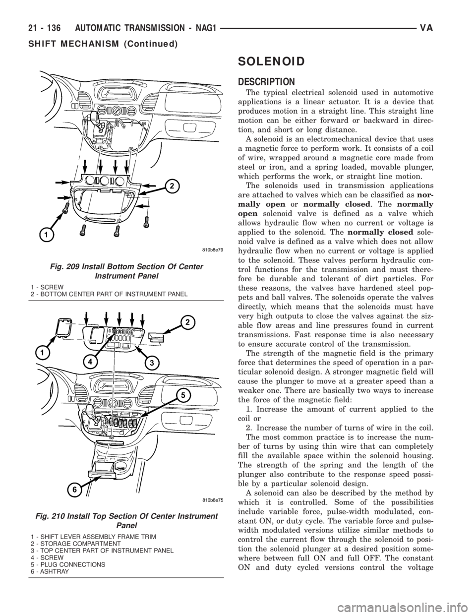
Fig. 209 Install Bottom Section Of Center
Instrument Panel
1 - SCREW
2 - BOTTOM CENTER PART OF INSTRUMENT PANEL
Fig. 210 Install Top Section Of Center Instrument
Panel
1 - SHIFT LEVER ASSEMBLY FRAME TRIM
2 - STORAGE COMPARTMENT
3 - TOP CENTER PART OF INSTRUMENT PANEL
4 - SCREW
5 - PLUG CONNECTIONS
6 - ASHTRAY
21 - 136 AUTOMATIC TRANSMISSION - NAG1VA
SHIFT MECHANISM (Continued)
Page 1014 of 1232
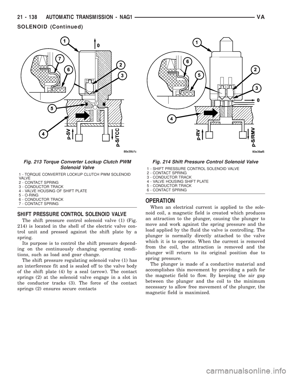
SHIFT PRESSURE CONTROL SOLENOID VALVE
The shift pressure control solenoid valve (1) (Fig.
214) is located in the shell of the electric valve con-
trol unit and pressed against the shift plate by a
spring.
Its purpose is to control the shift pressure depend-
ing on the continuously changing operating condi-
tions, such as load and gear change.
The shift pressure regulating solenoid valve (1) has
an interference fit and is sealed off to the valve body
of the shift plate (4) by a seal (arrow). The contact
springs (2) at the solenoid valve engage in a slot in
the conductor tracks (3). The force of the contact
springs (2) ensures secure contacts
OPERATION
When an electrical current is applied to the sole-
noid coil, a magnetic field is created which produces
an attraction to the plunger, causing the plunger to
move and work against the spring pressure and the
load applied by the fluid the valve is controlling. The
plunger is normally directly attached to the valve
which it is to operate. When the current is removed
from the coil, the attraction is removed and the
plunger will return to its original position due to
spring pressure.
The plunger is made of a conductive material and
accomplishes this movement by providing a path for
the magnetic field to flow. By keeping the air gap
between the plunger and the coil to the minimum
necessary to allow free movement of the plunger, the
magnetic field is maximized.
Fig. 213 Torque Converter Lockup Clutch PWM
Solenoid Valve
1 - TORQUE CONVERTER LOCKUP CLUTCH PWM SOLENOID
VA LV E
2 - CONTACT SPRING
3 - CONDUCTOR TRACK
4 - VALVE HOUSING OF SHIFT PLATE
5 - O-RING
6 - CONDUCTOR TRACK
7 - CONTACT SPRING
Fig. 214 Shift Pressure Control Solenoid Valve
1 - SHIFT PRESSURE CONTROL SOLENOID VALVE
2 - CONTACT SPRING
3 - CONDUCTOR TRACK
4 - VALVE HOUSING SHIFT PLATE
5 - CONDUCTOR TRACK
6 - CONTACT SPRING
21 - 138 AUTOMATIC TRANSMISSION - NAG1VA
SOLENOID (Continued)
Page 1016 of 1232
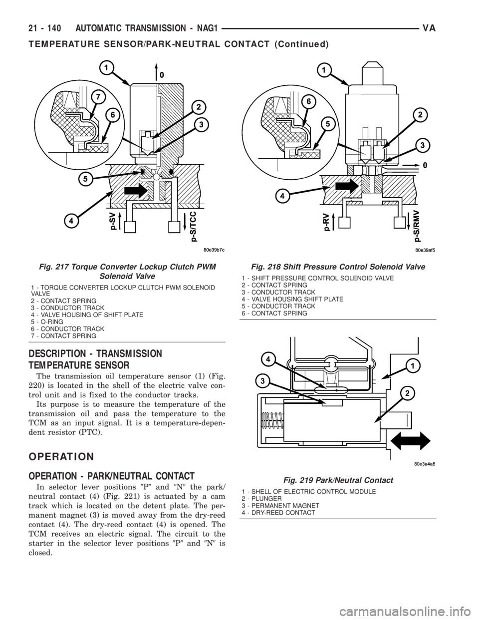
DESCRIPTION - TRANSMISSION
TEMPERATURE SENSOR
The transmission oil temperature sensor (1) (Fig.
220) is located in the shell of the electric valve con-
trol unit and is fixed to the conductor tracks.
Its purpose is to measure the temperature of the
transmission oil and pass the temperature to the
TCM as an input signal. It is a temperature-depen-
dent resistor (PTC).
OPERATION
OPERATION - PARK/NEUTRAL CONTACT
In selector lever positions9P9and9N9the park/
neutral contact (4) (Fig. 221) is actuated by a cam
track which is located on the detent plate. The per-
manent magnet (3) is moved away from the dry-reed
contact (4). The dry-reed contact (4) is opened. The
TCM receives an electric signal. The circuit to the
starter in the selector lever positions9P9and9N9is
closed.
Fig. 217 Torque Converter Lockup Clutch PWM
Solenoid Valve
1 - TORQUE CONVERTER LOCKUP CLUTCH PWM SOLENOID
VA LV E
2 - CONTACT SPRING
3 - CONDUCTOR TRACK
4 - VALVE HOUSING OF SHIFT PLATE
5 - O-RING
6 - CONDUCTOR TRACK
7 - CONTACT SPRING
Fig. 218 Shift Pressure Control Solenoid Valve
1 - SHIFT PRESSURE CONTROL SOLENOID VALVE
2 - CONTACT SPRING
3 - CONDUCTOR TRACK
4 - VALVE HOUSING SHIFT PLATE
5 - CONDUCTOR TRACK
6 - CONTACT SPRING
Fig. 219 Park/Neutral Contact
1 - SHELL OF ELECTRIC CONTROL MODULE
2 - PLUNGER
3 - PERMANENT MAGNET
4 - DRY-REED CONTACT
21 - 140 AUTOMATIC TRANSMISSION - NAG1VA
TEMPERATURE SENSOR/PARK-NEUTRAL CONTACT (Continued)
Page 1019 of 1232
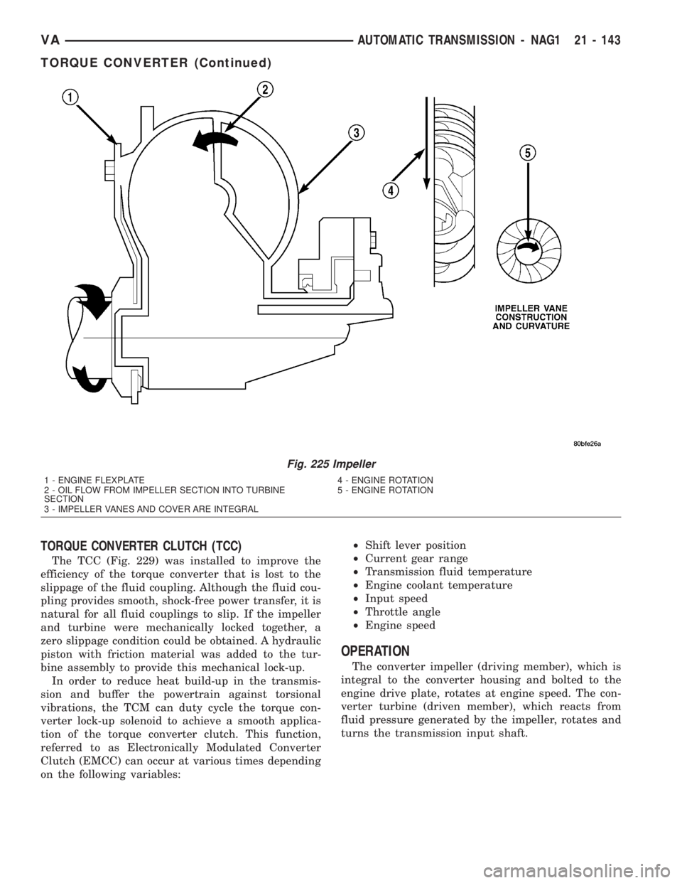
TORQUE CONVERTER CLUTCH (TCC)
The TCC (Fig. 229) was installed to improve the
efficiency of the torque converter that is lost to the
slippage of the fluid coupling. Although the fluid cou-
pling provides smooth, shock-free power transfer, it is
natural for all fluid couplings to slip. If the impeller
and turbine were mechanically locked together, a
zero slippage condition could be obtained. A hydraulic
piston with friction material was added to the tur-
bine assembly to provide this mechanical lock-up.
In order to reduce heat build-up in the transmis-
sion and buffer the powertrain against torsional
vibrations, the TCM can duty cycle the torque con-
verter lock-up solenoid to achieve a smooth applica-
tion of the torque converter clutch. This function,
referred to as Electronically Modulated Converter
Clutch (EMCC) can occur at various times depending
on the following variables:²Shift lever position
²Current gear range
²Transmission fluid temperature
²Engine coolant temperature
²Input speed
²Throttle angle
²Engine speed
OPERATION
The converter impeller (driving member), which is
integral to the converter housing and bolted to the
engine drive plate, rotates at engine speed. The con-
verter turbine (driven member), which reacts from
fluid pressure generated by the impeller, rotates and
turns the transmission input shaft.
Fig. 225 Impeller
1 - ENGINE FLEXPLATE 4 - ENGINE ROTATION
2 - OIL FLOW FROM IMPELLER SECTION INTO TURBINE
SECTION5 - ENGINE ROTATION
3 - IMPELLER VANES AND COVER ARE INTEGRAL
VAAUTOMATIC TRANSMISSION - NAG1 21 - 143
TORQUE CONVERTER (Continued)
Page 1077 of 1232
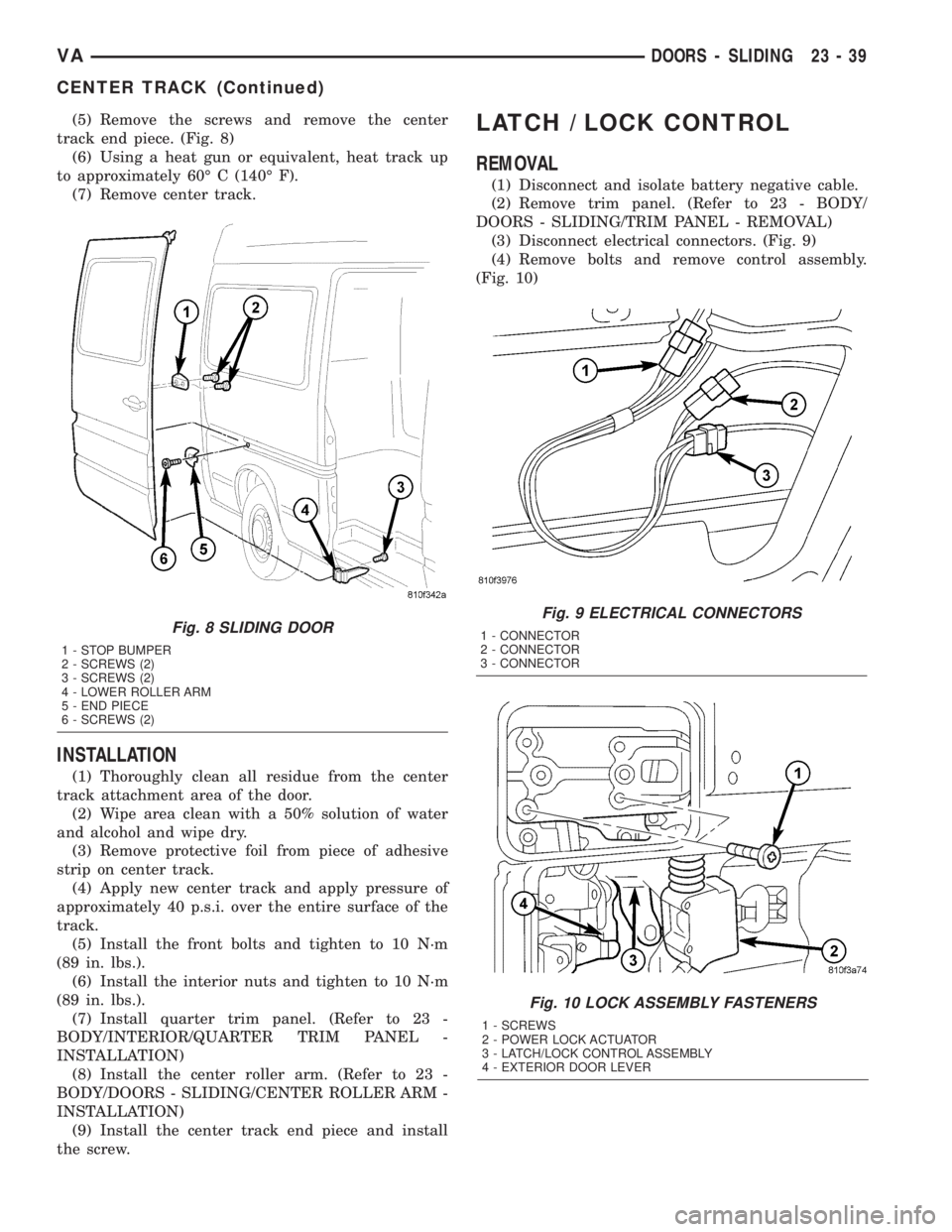
(5) Remove the screws and remove the center
track end piece. (Fig. 8)
(6) Using a heat gun or equivalent, heat track up
to approximately 60É C (140É F).
(7) Remove center track.
INSTALLATION
(1) Thoroughly clean all residue from the center
track attachment area of the door.
(2) Wipe area clean with a 50% solution of water
and alcohol and wipe dry.
(3) Remove protective foil from piece of adhesive
strip on center track.
(4) Apply new center track and apply pressure of
approximately 40 p.s.i. over the entire surface of the
track.
(5) Install the front bolts and tighten to 10 N´m
(89 in. lbs.).
(6) Install the interior nuts and tighten to 10 N´m
(89 in. lbs.).
(7) Install quarter trim panel. (Refer to 23 -
BODY/INTERIOR/QUARTER TRIM PANEL -
INSTALLATION)
(8) Install the center roller arm. (Refer to 23 -
BODY/DOORS - SLIDING/CENTER ROLLER ARM -
INSTALLATION)
(9) Install the center track end piece and install
the screw.
LATCH / LOCK CONTROL
REMOVAL
(1) Disconnect and isolate battery negative cable.
(2) Remove trim panel. (Refer to 23 - BODY/
DOORS - SLIDING/TRIM PANEL - REMOVAL)
(3) Disconnect electrical connectors. (Fig. 9)
(4) Remove bolts and remove control assembly.
(Fig. 10)
Fig. 9 ELECTRICAL CONNECTORS
1 - CONNECTOR
2 - CONNECTOR
3 - CONNECTOR
Fig. 10 LOCK ASSEMBLY FASTENERS
1 - SCREWS
2 - POWER LOCK ACTUATOR
3 - LATCH/LOCK CONTROL ASSEMBLY
4 - EXTERIOR DOOR LEVER
Fig. 8 SLIDING DOOR
1 - STOP BUMPER
2 - SCREWS (2)
3 - SCREWS (2)
4 - LOWER ROLLER ARM
5 - END PIECE
6 - SCREWS (2)
VADOORS - SLIDING 23 - 39
CENTER TRACK (Continued)