2005 MERCEDES-BENZ SPRINTER engine
[x] Cancel search: enginePage 1136 of 1232
CONTROLS - FRONT
TABLE OF CONTENTS
page page
A/C COMPRESSOR CLUTCH
DESCRIPTION..........................8
OPERATION............................8
STANDARD PROCEDURE
STANDARD PROCEDURE - COMPRESSOR
CLUTCH AIR GAP......................9
STANDARD PROCEDURE - COMPRESSOR
CLUTCH BREAK-IN.....................9
REMOVAL.............................9
INSPECTION - COMPRESSOR CLUTCH/COIL . 10
INSTALLATION.........................11
A/C COMPRESSOR CLUTCH COIL
DIAGNOSIS AND TESTING - COMPRESSOR
CLUTCH COIL........................12
A/C HEATER CONTROL
DESCRIPTION.........................12
OPERATION...........................12
REMOVAL.............................12
INSTALLATION.........................13
A/C PRESSURE TRANSDUCER
DESCRIPTION.........................13
OPERATION...........................13
DIAGNOSIS AND TESTING - A/C PRESSURE
TRANSDUCER.......................13
REMOVAL.............................14
INSTALLATION.........................14
AIR OUTLET TEMPERATURE SENSOR
DESCRIPTION.........................14
OPERATION...........................15
REMOVAL.............................15
INSTALLATION.........................15
AMBIENT TEMPERATURE SENSOR
DESCRIPTION.........................15
OPERATION...........................15REMOVAL.............................15
INSTALLATION.........................16
BLOWER MOTOR RESISTOR BLOCK
DESCRIPTION.........................16
OPERATION...........................16
DIAGNOSIS AND TESTING - BLOWER
MOTOR RESISTOR BLOCK..............16
REMOVAL.............................16
INSTALLATION.........................17
BLOWER MOTOR SWITCH
DESCRIPTION.........................17
OPERATION...........................17
DIAGNOSIS AND TESTING - BLOWER
MOTOR SWITCH......................17
REMOVAL.............................17
EVAPORATOR TEMPERATURE SENSOR
DESCRIPTION.........................17
OPERATION...........................18
REMOVAL.............................18
INSTALLATION.........................18
IN-CAR TEMPERATURE SENSOR
DESCRIPTION.........................19
OPERATION...........................19
DIAGNOSIS AND TESTING................19
REMOVAL.............................19
MODE DOOR CABLES
REMOVAL.............................19
INSTALLATION.........................19
RECIRCULATION DOOR ACTUATOR
DESCRIPTION.........................20
OPERATION...........................20
REMOVAL.............................21
INSTALLATION.........................21
A/C COMPRESSOR CLUTCH
DESCRIPTION
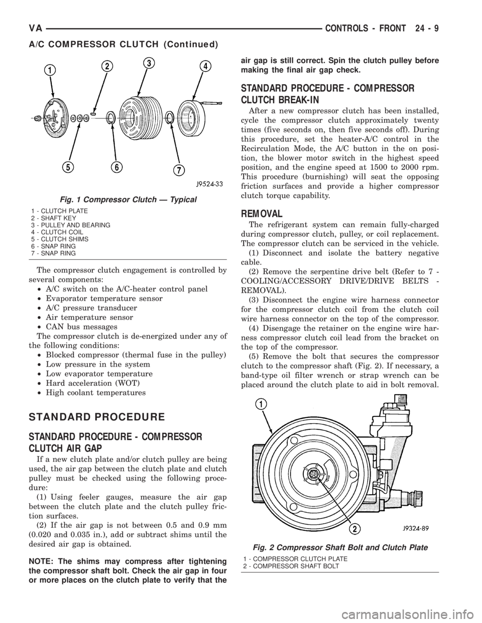
The compressor clutch assembly consists of a sta-
tionary electromagnetic coil, a hub bearing and pul-
ley assembly, and a clutch plate (Fig. 1). The
electromagnetic coil unit and the hub bearing and
pulley assembly are each retained on the nose of the
compressor front housing with snap rings. The clutch
plate is keyed to the compressor shaft and secured
with a bolt.
The compressor clutch plate and pully, or the clutch
coil are available for seperate service replacement.
OPERATION
The compressor clutch components provide the
means to engage and disengage the compressor from
the engine serpentine accessory drive belt. When the
clutch coil is energized, it magnetically draws the
clutch into contact with the pulley and drives the
compressor shaft. When the coil is not energized, the
pulley freewheels on the clutch hub bearing, which is
part of the pulley.
24 - 8 CONTROLS - FRONTVA
Page 1137 of 1232
The compressor clutch engagement is controlled by
several components:
²A/C switch on the A/C-heater control panel
²Evaporator temperature sensor
²A/C pressure transducer
²Air temperature sensor
²CAN bus messages
The compressor clutch is de-energized under any of
the following conditions:
²Blocked compressor (thermal fuse in the pulley)
²Low pressure in the system
²Low evaporator temperature
²Hard acceleration (WOT)
²High coolant temperatures
STANDARD PROCEDURE
STANDARD PROCEDURE - COMPRESSOR
CLUTCH AIR GAP
If a new clutch plate and/or clutch pulley are being
used, the air gap between the clutch plate and clutch
pulley must be checked using the following proce-
dure:
(1) Using feeler gauges, measure the air gap
between the clutch plate and the clutch pulley fric-
tion surfaces.
(2) If the air gap is not between 0.5 and 0.9 mm
(0.020 and 0.035 in.), add or subtract shims until the
desired air gap is obtained.
NOTE: The shims may compress after tightening
the compressor shaft bolt. Check the air gap in four
or more places on the clutch plate to verify that theair gap is still correct. Spin the clutch pulley before
making the final air gap check.
STANDARD PROCEDURE - COMPRESSOR
CLUTCH BREAK-IN
After a new compressor clutch has been installed,
cycle the compressor clutch approximately twenty
times (five seconds on, then five seconds off). During
this procedure, set the heater-A/C control in the
Recirculation Mode, the A/C button in the on posi-
tion, the blower motor switch in the highest speed
position, and the engine speed at 1500 to 2000 rpm.
This procedure (burnishing) will seat the opposing
friction surfaces and provide a higher compressor
clutch torque capability.
REMOVAL
The refrigerant system can remain fully-charged
during compressor clutch, pulley, or coil replacement.
The compressor clutch can be serviced in the vehicle.
(1) Disconnect and isolate the battery negative
cable.
(2) Remove the serpentine drive belt (Refer to 7 -
COOLING/ACCESSORY DRIVE/DRIVE BELTS -
REMOVAL).
(3) Disconnect the engine wire harness connector
for the compressor clutch coil from the clutch coil
wire harness connector on the top of the compressor.
(4) Disengage the retainer on the engine wire har-
ness compressor clutch coil lead from the bracket on
the top of the compressor.
(5) Remove the bolt that secures the compressor
clutch to the compressor shaft (Fig. 2). If necessary, a
band-type oil filter wrench or strap wrench can be
placed around the clutch plate to aid in bolt removal.
Fig. 1 Compressor Clutch Ð Typical
1 - CLUTCH PLATE
2 - SHAFT KEY
3 - PULLEY AND BEARING
4 - CLUTCH COIL
5 - CLUTCH SHIMS
6 - SNAP RING
7 - SNAP RING
Fig. 2 Compressor Shaft Bolt and Clutch Plate
1 - COMPRESSOR CLUTCH PLATE
2 - COMPRESSOR SHAFT BOLT
VACONTROLS - FRONT 24 - 9
A/C COMPRESSOR CLUTCH (Continued)
Page 1139 of 1232
(2) Examine the friction surfaces of the clutch pul-
ley and the clutch plate for oil contamination. If the
friction surfaces are oily, the clutch pulley and clutch
plate should be replaced. Also inspect the shaft and
nose area of the compressor for oil. Remove the felt
packing from around the compressor shaft in the
compressor front cover. If the felt is saturated with
oil, the compressor front shaft seal is leaking and the
compressor will also have to be replaced.
(3) Check the clutch pulley bearing for roughness
or excessive leakage of grease. Replace the clutch
pulley and clutch plate if the bearing is faulty.
INSTALLATION
(1) Align the dowel pin on the back of the clutch
field coil with the hole in the compressor front cover,
and position the clutch coil onto the compressor. Be
certain that the cluch coil wire harness leads are
properly oriented and routed so that they are not
pinched between the compressor front cover and the
clutch coil.
NOTE: A new snap ring must be used to secure the
clutch coil to the compressor. The bevel side of the
snap ring must face outward.
(2) Using snap ring pliers (Special Tool C-4574 or
equivalent), install the external snap ring that
secures the clutch coil to the front cover of the com-
pressor. The bevel side of the snap ring must be fac-
ing outward and both snap ring eyelets must be
oriented to the right or left of the clutch coil dowel
pin on the compressor. Be certain that the snap ring
is fully and properly seated in the groove.
CAUTION: If the snap ring is not fully seated in the
groove it will vibrate out, resulting in a clutch fail-
ure and severe damage to the compressor front
cover.
(3) Install and tighten the screw that secures the
clutch coil wire harness connector bracket and
ground clip to the top of the compressor housing.
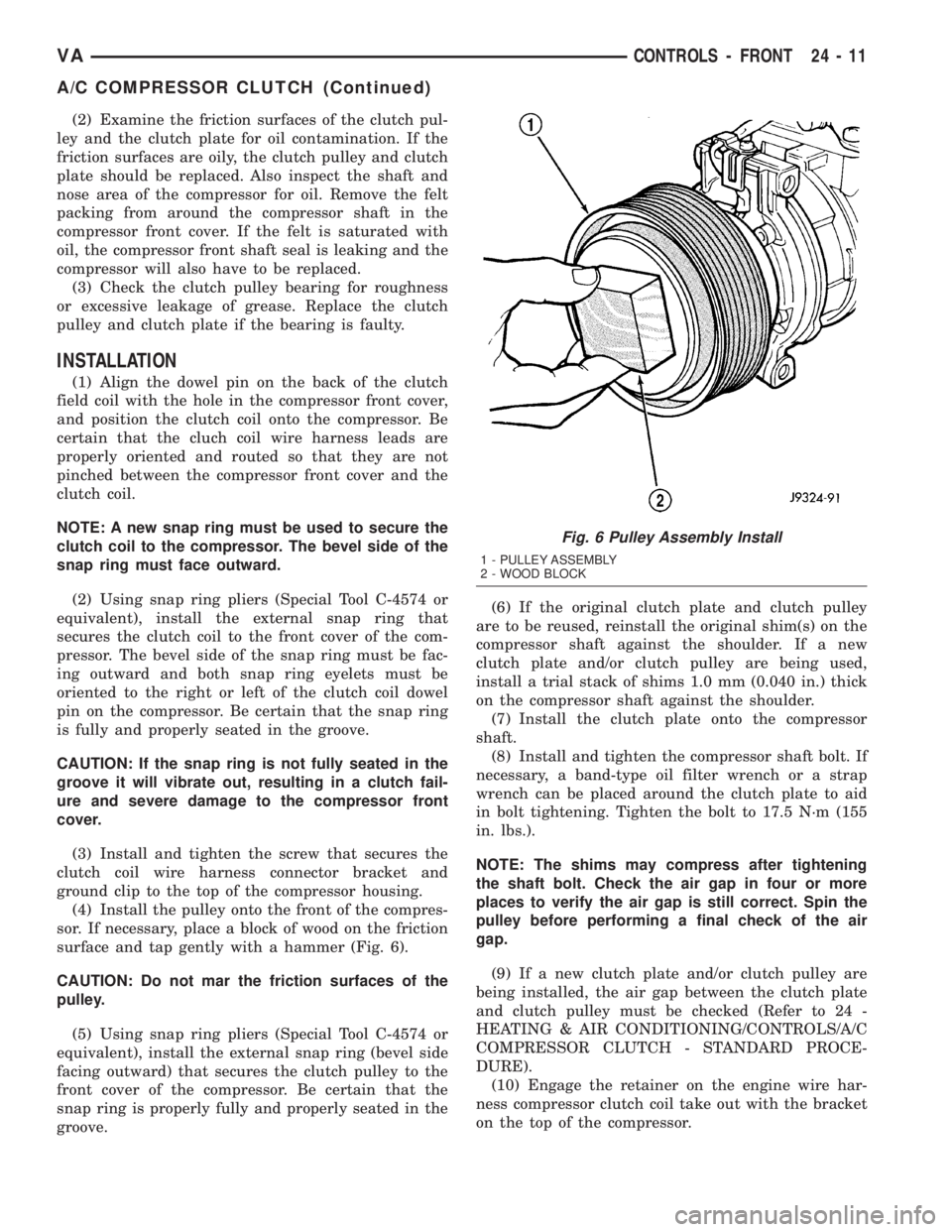
(4) Install the pulley onto the front of the compres-
sor. If necessary, place a block of wood on the friction
surface and tap gently with a hammer (Fig. 6).
CAUTION: Do not mar the friction surfaces of the
pulley.
(5) Using snap ring pliers (Special Tool C-4574 or
equivalent), install the external snap ring (bevel side
facing outward) that secures the clutch pulley to the
front cover of the compressor. Be certain that the
snap ring is properly fully and properly seated in the
groove.(6) If the original clutch plate and clutch pulley
are to be reused, reinstall the original shim(s) on the
compressor shaft against the shoulder. If a new
clutch plate and/or clutch pulley are being used,
install a trial stack of shims 1.0 mm (0.040 in.) thick
on the compressor shaft against the shoulder.
(7) Install the clutch plate onto the compressor
shaft.
(8) Install and tighten the compressor shaft bolt. If
necessary, a band-type oil filter wrench or a strap
wrench can be placed around the clutch plate to aid
in bolt tightening. Tighten the bolt to 17.5 N´m (155
in. lbs.).
NOTE: The shims may compress after tightening
the shaft bolt. Check the air gap in four or more
places to verify the air gap is still correct. Spin the
pulley before performing a final check of the air
gap.
(9) If a new clutch plate and/or clutch pulley are
being installed, the air gap between the clutch plate
and clutch pulley must be checked (Refer to 24 -
HEATING & AIR CONDITIONING/CONTROLS/A/C
COMPRESSOR CLUTCH - STANDARD PROCE-
DURE).
(10) Engage the retainer on the engine wire har-
ness compressor clutch coil take out with the bracket
on the top of the compressor.
Fig. 6 Pulley Assembly Install
1 - PULLEY ASSEMBLY
2 - WOOD BLOCK
VACONTROLS - FRONT 24 - 11
A/C COMPRESSOR CLUTCH (Continued)
Page 1140 of 1232
(11) Reconnect the engine wire harness connector
for the compressor clutch coil to the coil wire harness
connector on the top of the compressor.
(12) Reinstall the serpentine accessory drive belt
(Refer to 7 - COOLING/ACCESSORY DRIVE/DRIVE
BELTS - INSTALLATION).
(13) Reconnect the battery negative cable.
(14) If a new clutch plate and/or clutch pulley are
being installed, the new clutch components must be
burnished (Refer to 24 - HEATING & AIR CONDI-
TIONING/CONTROLS/A/C COMPRESSOR CLUTCH
- STANDARD PROCEDURE).
A/C COMPRESSOR CLUTCH
COIL
DIAGNOSIS AND TESTING - COMPRESSOR
CLUTCH COIL
The air conditioning compressor clutch coil electri-
cal circuit is controlled by the ATC control module
which is integral to the heater-A/C control. Begin
testing of a suspected compressor clutch coil problem
by performing the ATC Function Test using the
DRBIIItscan tool.
A/C HEATER CONTROL
DESCRIPTION
This ATC system uses a combination of electrical
and mechanical controls. These controls provide the
vehicle operator with a number of setting options to
help control the climate and comfort within the vehi-
cle.
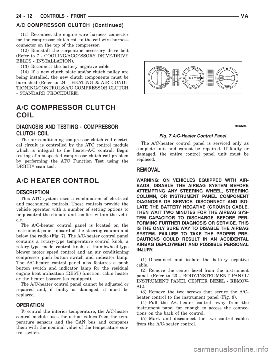
The A/C-heater control panel is located on the
instrument panel inboard of the steering column and
below the radio (Fig. 7). The A/C-heater control panel
contains a rotary-type temperature control knob, a
rotary-type mode control knob, a thumbwheel-type
blower motor speed control and an air conditioning
compressor push button switch and indicator lamp.
The A/C-heater control panel also features a push
button switch and indicator lamp for the residual
engine heat utilization (REST) function, cabin heater
or the heater booster (as equipped).
The A/C-heater control panel cannot be adjusted or
repaired and, if faulty or damaged, it must be
replaced.
OPERATION
To control the interior temperature, the A/C-heater
control module uses the actual values from the tem-
perature sensors and the CAN bus and compares
them with the nominal value of the temperature con-
trol switch.The A/C-heater control panel is serviced only as
complete unit and cannot be repaired. If faulty or
damaged, the entire control panel unit must be
replaced.
REMOVAL
WARNING: ON VEHICLES EQUIPPED WITH AIR-
BAGS, DISABLE THE AIRBAG SYSTEM BEFORE
ATTEMPTING ANY STEERING WHEEL, STEERING
COLUMN, OR INSTRUMENT PANEL COMPONENT
DIAGNOSIS OR SERVICE. DISCONNECT AND ISO-
LATE THE BATTERY NEGATIVE (GROUND) CABLE,
THEN WAIT TWO MINUTES FOR THE AIRBAG SYS-
TEM CAPACITOR TO DISCHARGE BEFORE PER-
FORMING FURTHER DIAGNOSIS OR SERVICE. THIS
IS THE ONLY SURE WAY TO DISABLE THE AIRBAG
SYSTEM. FAILURE TO TAKE THE PROPER PRE-
CAUTIONS COULD RESULT IN AN ACCIDENTAL
AIRBAG DEPLOYMENT AND POSSIBLE PERSONAL
INJURY.
(1) Disconnect and isolate the battery negative
cable.
(2) Remove the center bezel from the instrument
panel. (Refer to 23 - BODY/INSTRUMENT PANEL/
INSTRUMENT PANEL CENTER BEZEL - REMOV-
AL).
(3) Remove the two screws that secure the A/C-
heater control to the instrument panel (Fig. 8).
(4) Pull the A/C-heater control away from the
instrument panel far enough to access the connec-
tions on the back of the control.
(5) Mark and disconnect the two control cables
from the A/C-heater control.
Fig. 7 A/C-Heater Control Panel
24 - 12 CONTROLS - FRONTVA
A/C COMPRESSOR CLUTCH (Continued)
Page 1144 of 1232
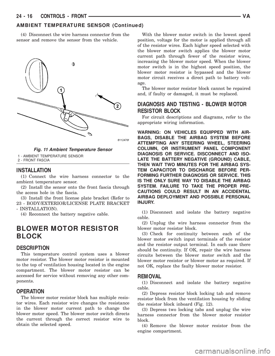
(4) Disconnect the wire harness connector from the
sensor and remove the sensor from the vehicle.
INSTALLATION
(1) Connect the wire harness connector to the
ambient temperature sensor.
(2) Install the sensor onto the front fascia through
the access hole in the fascia.
(3) Install the front license plate bracket (Refer to
23 - BODY/EXTERIOR/LICENSE PLATE BRACKET
- INSTALLATION).
(4) Reconnect the battery negative cable.
BLOWER MOTOR RESISTOR
BLOCK
DESCRIPTION
This temperature control system uses a blower
motor resistor. The blower motor resistor is mounted
to the top of ventilation housing located in the engine
compartment. The blower motor resistor can be
accessed for service without removing any other com-
ponents.
OPERATION
The blower motor resistor block has multiple resis-
tor wires. Each resistor wire changes the resistance
in the blower motor current path to change the
blower motor speed. The blower motor switch directs
the current through the correct resistor wire to
obtain the selected speed.With the blower motor switch in the lowest speed
position, voltage for the motor is applied through all
of the resistor wires. Each higher speed selected with
the blower motor switch applies the blower motor
current path through fewer of the resistor wires,
increasing the blower motor speed. When the blower
motor switch is in the highest speed position, the
blower motor resistor is bypassed and the blower
motor circuit receives a direct path to battery volt-
age.
The blower motor resistor block cannot be repaired
and, if faulty or damaged, it must be replaced.
DIAGNOSIS AND TESTING - BLOWER MOTOR
RESISTOR BLOCK
For circuit descriptions and diagrams, refer to the
appropriate wiring information.
WARNING: ON VEHICLES EQUIPPED WITH AIR-
BAGS, DISABLE THE AIRBAG SYSTEM BEFORE
ATTEMPTING ANY STEERING WHEEL, STEERING
COLUMN, OR INSTRUMENT PANEL COMPONENT
DIAGNOSIS OR SERVICE. DISCONNECT AND ISO-
LATE THE BATTERY NEGATIVE (GROUND) CABLE,
THEN WAIT TWO MINUTES FOR THE AIRBAG SYS-
TEM CAPACITOR TO DISCHARGE BEFORE PER-
FORMING FURTHER DIAGNOSIS OR SERVICE. THIS
IS THE ONLY SURE WAY TO DISABLE THE AIRBAG
SYSTEM. FAILURE TO TAKE THE PROPER PRE-
CAUTIONS COULD RESULT IN AN ACCIDENTAL
AIRBAG DEPLOYMENT AND POSSIBLE PERSONAL
INJURY.
(1) Disconnect and isolate the battery negative
cable.
(2) Unplug the wire harness connector from the
blower motor resistor block.
(3) Check for continuity between each of the
blower motor switch input terminals of the resistor
and the resistor output terminal. In each case there
should be continuity. If OK, repair the wire harness
circuits between the blower motor switch and the
blower motor resistor or blower motor as required. If
not OK, replace the faulty blower motor resistor.
REMOVAL
(1) Disconnect and isolate the battery negative
cable.
(2) Depress resistor block locking tab and remove
resistor block from the ventilation housing by sliding
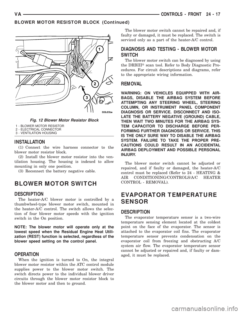
the resistor block inboard (Fig. 12).
(3) Depress two locking tabs and unplug the wire
harness connector from the blower motor resistor
block.
(4) Remove the blower motor resistor from the
engine compartment.
Fig. 11 Ambient Temperature Sensor
1 - AMBIENT TEMPERATURE SENSOR
2 - FRONT FASCIA
24 - 16 CONTROLS - FRONTVA
AMBIENT TEMPERATURE SENSOR (Continued)
Page 1145 of 1232
INSTALLATION
(1) Connect the wire harness connector to the
blower motor resistor block.
(2) Install the blower motor resistor into the ven-
tilation housing. The housing is indexed to allow
mounting in only one position.
(3) Reconnect the battery negative cable.
BLOWER MOTOR SWITCH
DESCRIPTION
The heater-A/C blower motor is controlled by a
thumbwheel-type blower motor switch, mounted in
the heater-A/C control. The switch allows the selec-
tion of four blower motor speeds with the ignition
switch in the On position.
NOTE: The blower motor will operate only at the
lowest speed when the Residual Engine Heat Utili-
zation (REST) function is selected, regardless of the
blower speed setting on the control panel.
OPERATION
When the ignition is turned to On, the integral
blower motor resistor within the ATC control module
supplies power to the blower motor switch. The
switch directs power to the individual blower driver
circuits through the blower motor resistor block to
the blower motor and then to ground.The blower motor switch cannot be repaired and, if
faulty or damaged, it must be replaced. The switch is
serviced only as a part of the heater-A/C control.
DIAGNOSIS AND TESTING - BLOWER MOTOR
SWITCH
The blower motor switch can be diagnosed by using
the DRBIIItscan tool. Refer to Body Diagnostic Pro-
cedures. For circuit descriptions and diagrams, refer
to the appropriate wiring information.
REMOVAL
WARNING: ON VEHICLES EQUIPPED WITH AIR-
BAGS, DISABLE THE AIRBAG SYSTEM BEFORE
ATTEMPTING ANY STEERING WHEEL, STEERING
COLUMN, OR INSTRUMENT PANEL COMPONENT
DIAGNOSIS OR SERVICE. DISCONNECT AND ISO-
LATE THE BATTERY NEGATIVE (GROUND) CABLE,
THEN WAIT TWO MINUTES FOR THE AIRBAG SYS-
TEM CAPACITOR TO DISCHARGE BEFORE PER-
FORMING FURTHER DIAGNOSIS OR SERVICE. THIS
IS THE ONLY SURE WAY TO DISABLE THE AIRBAG
SYSTEM. FAILURE TO TAKE THE PROPER PRE-
CAUTIONS COULD RESULT IN AN ACCIDENTAL
AIRBAG DEPLOYMENT AND POSSIBLE PERSONAL
INJURY.
The blower motor switch cannot be adjusted or
repaired, and if faulty or damaged, the heater-A/C
control must be replaced (Refer to 24 - HEATING &
AIR CONDITIONING/CONTROLS/A/C HEATER
CONTROL - REMOVAL).
EVAPORATOR TEMPERATURE
SENSOR
DESCRIPTION
The evaporator temperature sensor is a two-wire
temperature sensing element located at the coldest
point on the face of the evaporator. The sensor is
attached to the evaporator coil fins. The evaporator
temperature sensor prevents condensation on the
evaporator coil from freezing and obstructing A/C
system air flow. The evaporator temperature sensor
cannot be adjusted or repaired and, if faulty or dam-
aged, it must be replaced.
Fig. 12 Blower Motor Resistor Block
1 - BLOWER MOTOR RESISTOR
2 - ELECTRICAL CONNECTOR
3 - VENTILATION HOUSING
VACONTROLS - FRONT 24 - 17
BLOWER MOTOR RESISTOR BLOCK (Continued)
Page 1148 of 1232
NOTE: While holding the A/C-heater control in the
installation position, verify that the control cables
are not twisted.
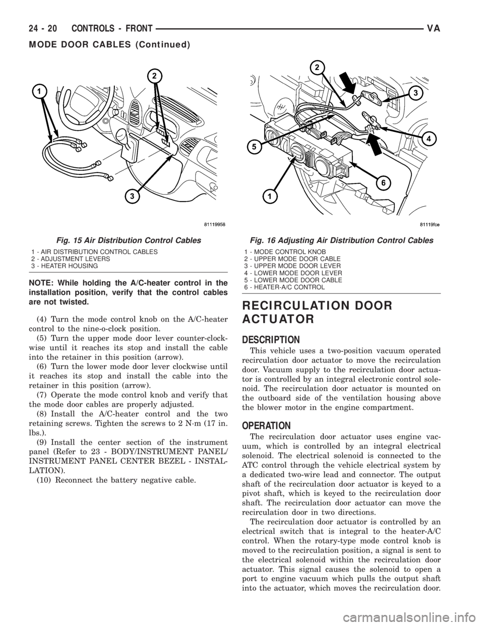
(4) Turn the mode control knob on the A/C-heater
control to the nine-o-clock position.
(5) Turn the upper mode door lever counter-clock-
wise until it reaches its stop and install the cable
into the retainer in this position (arrow).
(6) Turn the lower mode door lever clockwise until
it reaches its stop and install the cable into the
retainer in this position (arrow).
(7) Operate the mode control knob and verify that
the mode door cables are properly adjusted.
(8) Install the A/C-heater control and the two
retaining screws. Tighten the screws to 2 N´m (17 in.
lbs.).
(9) Install the center section of the instrument
panel (Refer to 23 - BODY/INSTRUMENT PANEL/
INSTRUMENT PANEL CENTER BEZEL - INSTAL-
LATION).
(10) Reconnect the battery negative cable.
RECIRCULATION DOOR
ACTUATOR
DESCRIPTION
This vehicle uses a two-position vacuum operated
recirculation door actuator to move the recirculation
door. Vacuum supply to the recirculation door actua-
tor is controlled by an integral electronic control sole-
noid. The recirculation door actuator is mounted on
the outboard side of the ventilation housing above
the blower motor in the engine compartment.
OPERATION
The recirculation door actuator uses engine vac-
uum, which is controlled by an integral electrical
solenoid. The electrical solenoid is connected to the
ATC control through the vehicle electrical system by
a dedicated two-wire lead and connector. The output
shaft of the recirculation door actuator is keyed to a
pivot shaft, which is keyed to the recirculation door
shaft. The recirculation door actuator can move the
recirculation door in two directions.
The recirculation door actuator is controlled by an
electrical switch that is integral to the heater-A/C
control. When the rotary-type mode control knob is
moved to the recirculation position, a signal is sent to
the electrical solenoid within the recirculation door
actuator. This signal causes the solenoid to open a
port to engine vacuum which pulls the output shaft
into the actuator, which moves the recirculation door.
Fig. 15 Air Distribution Control Cables
1 - AIR DISTRIBUTION CONTROL CABLES
2 - ADJUSTMENT LEVERS
3 - HEATER HOUSING
Fig. 16 Adjusting Air Distribution Control Cables
1 - MODE CONTROL KNOB
2 - UPPER MODE DOOR CABLE
3 - UPPER MODE DOOR LEVER
4 - LOWER MODE DOOR LEVER
5 - LOWER MODE DOOR CABLE
6 - HEATER-A/C CONTROL
24 - 20 CONTROLS - FRONTVA
MODE DOOR CABLES (Continued)
Page 1154 of 1232
The rear evaporator temperature sensor consists of
a probe and a switch unit. The probe, which is a Neg-
ative Temperature Coefficient (NTC) thermistor in a
capillary tube, is inserted between the rear evapora-
tor coil fins to monitor evaporator temperature. The
switch unit contains internal control logic that mon-
itors the input from the probe in order to switch an
internal transistor that controls the output signal to
the rear A/C control module.
OPERATION
When the rear evaporator temperature sensor sees
a temperature input below about 1.6É C (35É F), it
signals the rear A/C control module to cycle the rear
A/C solenoid valve closed. When the temperature
input reaches above about 3.9É C (39É F), the switch
signals the control module to cycle the valve open.
The rear evaporator temperature sensor can be
accessed for service by removing the air inlet grate
from the rear evaporator housing. The rear evapora-
tor temperature sensor cannot be adjusted or
repaired. If faulty or damaged, the sensor must be
replaced.
DIAGNOSIS AND TESTING
Before testing the rear evaporator temperature
sensor, verify that the front A/C system is operating
correctly by performing the ATC Function Test using
the DRBIIItscan tool. Use a volt/ohmmeter to test
the sensor. For circuit descriptions and diagrams,
refer to the appropriate wiring information. The wir-
ing information includes wiring diagrams, proper
wire and connector repair procedures, details of wire
harness routing and retention, connector pin-out
information and location views for the various wire
harness connectors, splices and grounds.
(1) Turn the ignition switch and the front A/C
switch to the On position. Place the rear blower
motor switch in either low or high speed position.
Check for voltage to the rear evaporator relay from
the rear evaporator temperature sensor. If OK, go to
Step 2. If not OK, repair the open or shorted evapo-
rator temperature sensor circuit as required.
(2) With the ambient temperature between 20 to
30É C (68 to 90É F), start the engine and run the rear
air conditioning system. The rear A/C solenoid valve
should cycle open and closed. Use a voltmeter con-
nected to the output side of the sensor for this check.
If the A/C solenoid valve fails to cycle in these tem-
peratures, replace the faulty rear evaporator temper-
ature sensor.
NOTE: If the ambient temperature is above 32É C
(90É F) the rear A/C solenoid valve may not cycle
due to the high heat load. This condition is normal.
REMOVAL
(1) Disconnect and isolate the battery negative
cable.
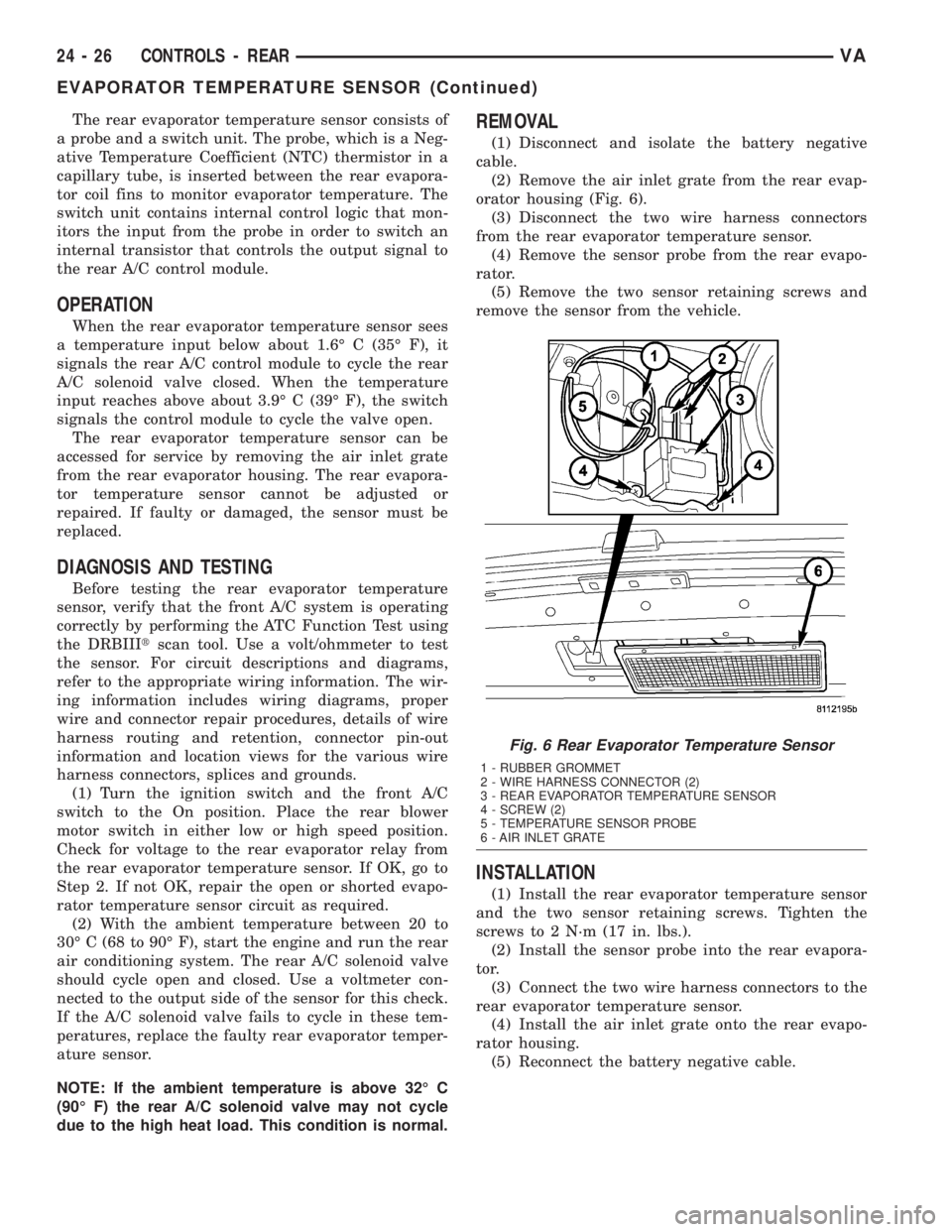
(2) Remove the air inlet grate from the rear evap-
orator housing (Fig. 6).
(3) Disconnect the two wire harness connectors
from the rear evaporator temperature sensor.
(4) Remove the sensor probe from the rear evapo-
rator.
(5) Remove the two sensor retaining screws and
remove the sensor from the vehicle.
INSTALLATION
(1) Install the rear evaporator temperature sensor
and the two sensor retaining screws. Tighten the
screws to 2 N´m (17 in. lbs.).
(2) Install the sensor probe into the rear evapora-
tor.
(3) Connect the two wire harness connectors to the
rear evaporator temperature sensor.
(4) Install the air inlet grate onto the rear evapo-
rator housing.
(5) Reconnect the battery negative cable.
Fig. 6 Rear Evaporator Temperature Sensor
1 - RUBBER GROMMET
2 - WIRE HARNESS CONNECTOR (2)
3 - REAR EVAPORATOR TEMPERATURE SENSOR
4 - SCREW (2)
5 - TEMPERATURE SENSOR PROBE
6 - AIR INLET GRATE
24 - 26 CONTROLS - REARVA
EVAPORATOR TEMPERATURE SENSOR (Continued)