2005 MERCEDES-BENZ SPRINTER engine
[x] Cancel search: enginePage 1022 of 1232
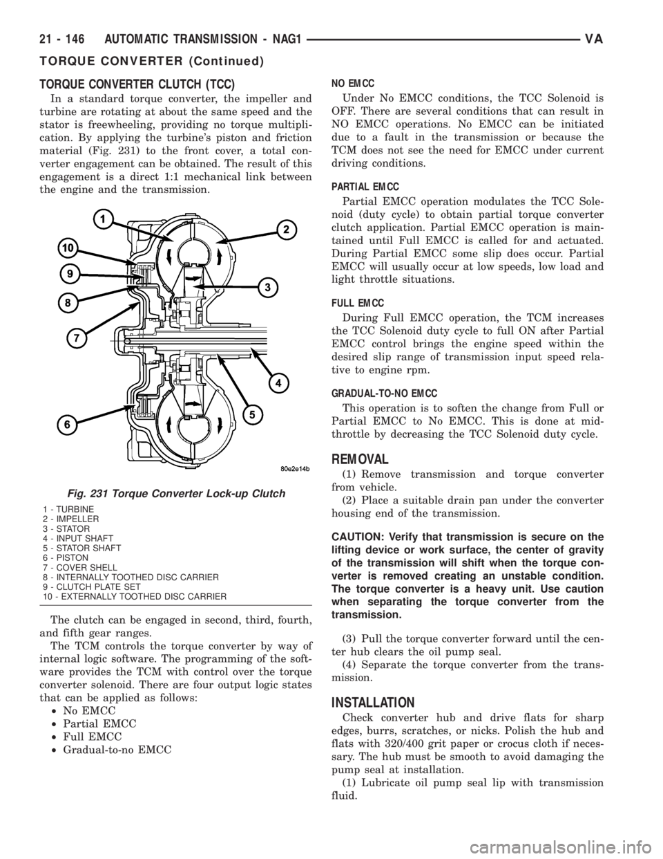
TORQUE CONVERTER CLUTCH (TCC)
In a standard torque converter, the impeller and
turbine are rotating at about the same speed and the
stator is freewheeling, providing no torque multipli-
cation. By applying the turbine's piston and friction
material (Fig. 231) to the front cover, a total con-
verter engagement can be obtained. The result of this
engagement is a direct 1:1 mechanical link between
the engine and the transmission.
The clutch can be engaged in second, third, fourth,
and fifth gear ranges.
The TCM controls the torque converter by way of
internal logic software. The programming of the soft-
ware provides the TCM with control over the torque
converter solenoid. There are four output logic states
that can be applied as follows:
²No EMCC
²Partial EMCC
²Full EMCC
²Gradual-to-no EMCCNO EMCC
Under No EMCC conditions, the TCC Solenoid is
OFF. There are several conditions that can result in
NO EMCC operations. No EMCC can be initiated
due to a fault in the transmission or because the
TCM does not see the need for EMCC under current
driving conditions.
PARTIAL EMCC
Partial EMCC operation modulates the TCC Sole-
noid (duty cycle) to obtain partial torque converter
clutch application. Partial EMCC operation is main-
tained until Full EMCC is called for and actuated.
During Partial EMCC some slip does occur. Partial
EMCC will usually occur at low speeds, low load and
light throttle situations.
FULL EMCC
During Full EMCC operation, the TCM increases
the TCC Solenoid duty cycle to full ON after Partial
EMCC control brings the engine speed within the
desired slip range of transmission input speed rela-
tive to engine rpm.
GRADUAL-TO-NO EMCC
This operation is to soften the change from Full or
Partial EMCC to No EMCC. This is done at mid-
throttle by decreasing the TCC Solenoid duty cycle.
REMOVAL
(1) Remove transmission and torque converter
from vehicle.
(2) Place a suitable drain pan under the converter
housing end of the transmission.
CAUTION: Verify that transmission is secure on the
lifting device or work surface, the center of gravity
of the transmission will shift when the torque con-
verter is removed creating an unstable condition.
The torque converter is a heavy unit. Use caution
when separating the torque converter from the
transmission.
(3) Pull the torque converter forward until the cen-
ter hub clears the oil pump seal.
(4) Separate the torque converter from the trans-
mission.
INSTALLATION
Check converter hub and drive flats for sharp
edges, burrs, scratches, or nicks. Polish the hub and
flats with 320/400 grit paper or crocus cloth if neces-
sary. The hub must be smooth to avoid damaging the
pump seal at installation.
(1) Lubricate oil pump seal lip with transmission
fluid.
Fig. 231 Torque Converter Lock-up Clutch
1 - TURBINE
2 - IMPELLER
3-STATOR
4 - INPUT SHAFT
5 - STATOR SHAFT
6 - PISTON
7 - COVER SHELL
8 - INTERNALLY TOOTHED DISC CARRIER
9 - CLUTCH PLATE SET
10 - EXTERNALLY TOOTHED DISC CARRIER
21 - 146 AUTOMATIC TRANSMISSION - NAG1VA
TORQUE CONVERTER (Continued)
Page 1030 of 1232
TIRES
DESCRIPTION
DESCRIPTION - TIRES
Tires are designed and engineered for each specific
vehicle. They provide the best overall performance
for normal operation. The ride and handling charac-
teristics match the vehicle's requirements. With
proper care they will give excellent reliability, trac-
tion, skid resistance, and tread life.
Driving habits have more effect on tire life than
any other factor. Careful drivers will obtain in most
cases, much greater mileage than severe use or care-
less drivers. A few of the driving habits which will
shorten the life of any tire are:
²Rapid acceleration
²Severe brake applications
²High speed driving
²Excessive speeds on turns
²Striking curbs and other obstacles
Radial-ply tires are more prone to irregular tread
wear. It is important to follow the tire rotation inter-
val shown in the section on Tire Rotation, (Refer to
22 - TIRES/WHEELS - STANDARD PROCEDURE).
This will help to achieve a greater tread life.
TIRE IDENTIFICATION
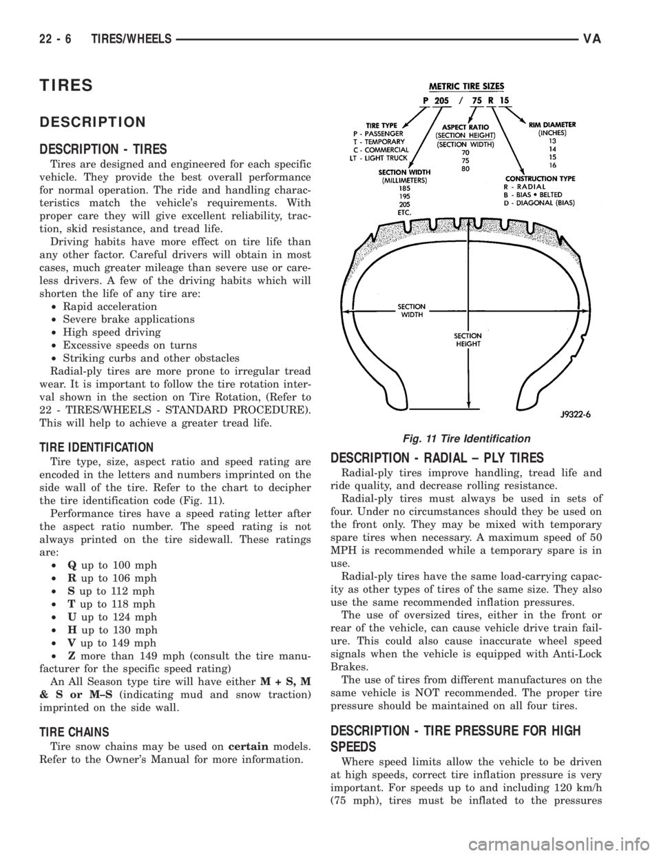
Tire type, size, aspect ratio and speed rating are
encoded in the letters and numbers imprinted on the
side wall of the tire. Refer to the chart to decipher
the tire identification code (Fig. 11).
Performance tires have a speed rating letter after
the aspect ratio number. The speed rating is not
always printed on the tire sidewall. These ratings
are:
²Qup to 100 mph
²Rup to 106 mph
²Sup to 112 mph
²Tup to 118 mph
²Uup to 124 mph
²Hup to 130 mph
²Vup to 149 mph
²Zmore than 149 mph (consult the tire manu-
facturer for the specific speed rating)
An All Season type tire will have eitherM+S,M
&SorM±S(indicating mud and snow traction)
imprinted on the side wall.
TIRE CHAINS
Tire snow chains may be used oncertainmodels.
Refer to the Owner's Manual for more information.
DESCRIPTION - RADIAL ± PLY TIRES
Radial-ply tires improve handling, tread life and
ride quality, and decrease rolling resistance.
Radial-ply tires must always be used in sets of
four. Under no circumstances should they be used on
the front only. They may be mixed with temporary
spare tires when necessary. A maximum speed of 50
MPH is recommended while a temporary spare is in
use.
Radial-ply tires have the same load-carrying capac-
ity as other types of tires of the same size. They also
use the same recommended inflation pressures.
The use of oversized tires, either in the front or
rear of the vehicle, can cause vehicle drive train fail-
ure. This could also cause inaccurate wheel speed
signals when the vehicle is equipped with Anti-Lock
Brakes.
The use of tires from different manufactures on the
same vehicle is NOT recommended. The proper tire
pressure should be maintained on all four tires.
DESCRIPTION - TIRE PRESSURE FOR HIGH
SPEEDS
Where speed limits allow the vehicle to be driven
at high speeds, correct tire inflation pressure is very
important. For speeds up to and including 120 km/h
(75 mph), tires must be inflated to the pressures
Fig. 11 Tire Identification
22 - 6 TIRES/WHEELSVA
Page 1032 of 1232
DIAGNOSIS AND TESTING
DIAGNOSIS AND TESTING - PRESSURE
GAUGES
A quality air pressure gauge is recommended to
check tire pressure. After checking the air pressure,
replace valve cap finger tight.
DIAGNOSIS AND TESTING - TIRE NOISE OR
VIBRATION
Radial-ply tires are sensitive to force impulses
caused by improper mounting, vibration, wheel
defects, or possibly tire imbalance.
To find out if tires are causing the noise or vibra-
tion, drive the vehicle over a smooth road at varying
speeds. Note the noise level during acceleration and
deceleration. The engine, differential and exhaust
noises will change as speed varies, while the tire
noise will usually remain constant.
DIAGNOSIS AND TESTING - TREAD WEAR
INDICATORS
Tread wear indicators are molded into the bottom
of the tread grooves. When tread depth is 1.6 mm
(1/16 in.), the tread wear indicators will appear as a
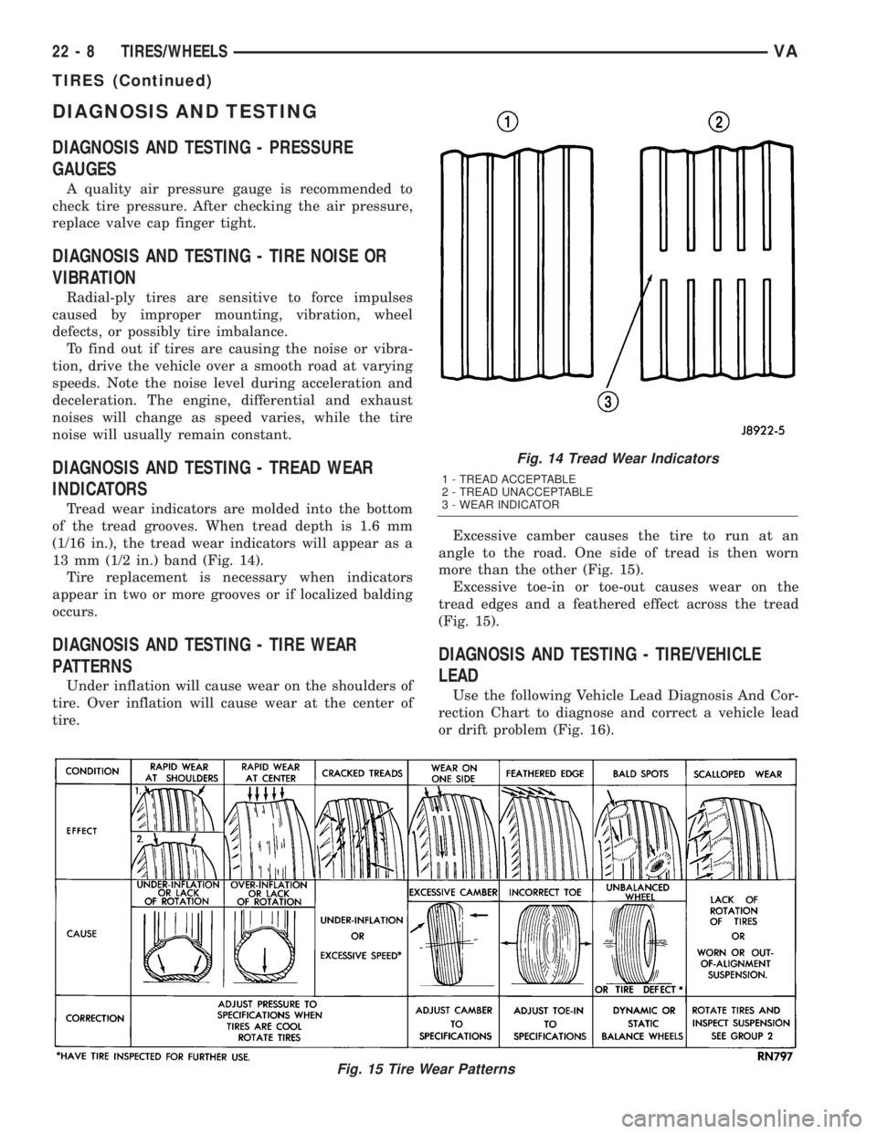
13 mm (1/2 in.) band (Fig. 14).
Tire replacement is necessary when indicators
appear in two or more grooves or if localized balding
occurs.
DIAGNOSIS AND TESTING - TIRE WEAR
PATTERNS
Under inflation will cause wear on the shoulders of
tire. Over inflation will cause wear at the center of
tire.Excessive camber causes the tire to run at an
angle to the road. One side of tread is then worn
more than the other (Fig. 15).
Excessive toe-in or toe-out causes wear on the
tread edges and a feathered effect across the tread
(Fig. 15).
DIAGNOSIS AND TESTING - TIRE/VEHICLE
LEAD
Use the following Vehicle Lead Diagnosis And Cor-
rection Chart to diagnose and correct a vehicle lead
or drift problem (Fig. 16).
Fig. 14 Tread Wear Indicators
1 - TREAD ACCEPTABLE
2 - TREAD UNACCEPTABLE
3 - WEAR INDICATOR
Fig. 15 Tire Wear Patterns
22 - 8 TIRES/WHEELSVA
TIRES (Continued)
Page 1040 of 1232
VISUAL INSPECTION BEFORE WATER LEAK TESTS
Verify that floor and body plugs are in place, body
drains are clear, and body components are properly
aligned and sealed. If component alignment or seal-
ing is necessary, refer to the appropriate section of
this group for proper procedures.
WATER LEAK TESTS
WARNING: DO NOT USE ELECTRIC SHOP LIGHTS
OR TOOLS IN WATER TEST AREA. PERSONAL
INJURY CAN RESULT.
When the conditions causing a water leak have
been determined, simulate the conditions as closely
as possible.
²If a leak occurs with the vehicle parked in a
steady light rain, flood the leak area with an open-
ended garden hose.
²If a leak occurs while driving at highway speeds
in a steady rain, test the leak area with a reasonable
velocity stream or fan spray of water. Direct the
spray in a direction comparable to actual conditions.
²If a leak occurs when the vehicle is parked on an
incline, hoist the end or side of the vehicle to simu-
late this condition. This method can be used when
the leak occurs when the vehicle accelerates, stops or
turns. If the leak occurs on acceleration, hoist the
front of the vehicle. If the leak occurs when braking,
hoist the back of the vehicle. If the leak occurs on left
turns, hoist the left side of the vehicle. If the leak
occurs on right turns, hoist the right side of the vehi-
cle. For hoisting recommendations (Refer to LUBRI-
CATION & MAINTENANCE/HOISTING -
STANDARD PROCEDURE).
WATER LEAK DETECTION
To detect a water leak point-of-entry, do a water
test and watch for water tracks or droplets forming
on the inside of the vehicle. If necessary, remove inte-
rior trim covers or panels to gain visual access to the
leak area. If the hose cannot be positioned without
being held, have someone help do the water test.
Some water leaks must be tested for a considerable
length of time to become apparent. When a leak
appears, find the highest point of the water track or
drop. The highest point usually will show the point of
entry. After leak point has been found, repair the
leak and water test to verify that the leak has
stopped.
Locating the entry point of water that is leaking
into a cavity between panels can be difficult. The
trapped water may splash or run from the cavity,
often at a distance from the entry point. Most water
leaks of this type become apparent after accelerating,
stopping, turning, or when on an incline.MIRROR INSPECTION METHOD
When a leak point area is visually obstructed, use
a suitable mirror to gain visual access. A mirror can
also be used to deflect light to a limited-access area
to assist in locating a leak point.
BRIGHT LIGHT LEAK TEST METHOD
Some water leaks in the luggage compartment can
be detected without water testing. Position the vehi-
cle in a brightly lit area. From inside the darkened
luggage compartment inspect around seals and body
seams. If necessary, have a helper direct a drop light
over the suspected leak areas around the luggage
compartment. If light is visible through a normally
sealed location, water could enter through the open-
ing.
PRESSURIZED LEAK TEST METHOD
When a water leak into the passenger compart-
ment cannot be detected by water testing, pressurize
the passenger compartment and soap test exterior of
the vehicle. To pressurize the passenger compart-
ment, close all doors and windows, start engine, and
set heater control to high blower in HEAT position. If
engine can not be started, connect a charger to the
battery to ensure adequate voltage to the blower.
With interior pressurized, apply dish detergent solu-
tion to suspected leak area on the exterior of the
vehicle. Apply detergent solution with spray device or
soft bristle brush. If soap bubbles occur at a body
seam, joint, seal or gasket, the leak entry point could
be at that location.
DIAGNOSIS AND TESTING - WIND NOISE
Wind noise is the result of most air leaks. Air leaks
can be caused by poor sealing, improper body compo-
nent alignment, body seam porosity, or missing plugs
in the engine compartment or door hinge pillar areas.
All body sealing points should be airtight in normal
driving conditions. Moving sealing surfaces will not
always seal airtight under all conditions. At times,
side glass or door seals will allow wind noise to be
noticed in the passenger compartment during high
cross winds. Over compensating on door or glass
adjustments to stop wind noise that occurs under
severe conditions can cause premature seal wear and
excessive closing or latching effort. After a repair pro-
cedure has been performed, test vehicle to verify
noise has stopped before returning vehicle to use.
VISUAL INSPECTION BEFORE TESTS
Verify that floor and body plugs are in place and
body components are aligned and sealed. If compo-
nent alignment or sealing is necessary, refer to the
appropriate section of this group for proper proce-
dures.
23 - 2 BODYVA
BODY (Continued)
Page 1089 of 1232
(4) Align hinges with installation reference marks
and tighten bolts to 23 N´m (17 ft. lbs.).
(5) Check and adjust as necessary. (Refer to 23 -
BODY/HOOD/HOOD - ADJUSTMENTS)
ADJUSTMENTS
ADJUSTMENT
SPECIFICATIONS
DESCRIPTION SPECIFICATION
Left and right hood gaps 5 0.5 mm
Flush offset for
hood/fender·1.0 mm
(1) Check hood to fender gap. Refer to the SPECI-
FICATIONS table.
(2) Loosen hinge to cowl bolts and adjust hood side
to side, if necessary.
(3) Tighten bolts to 23 N´m (17 ft. lbs.).
(4) Check hood to fender flushness. Refer to the
SPECIFICATIONS table.
(5) Loosen hinge to hood nuts and adjust hood up
and down, if necessary.
(6) Tighten nuts to 23 N´m (17 ft. lbs.).
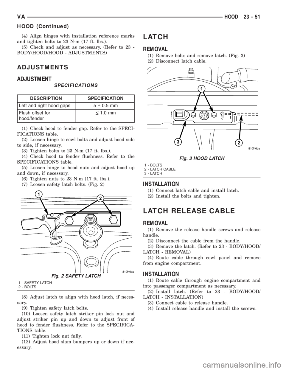
(7) Loosen safety latch bolts. (Fig. 2)
(8) Adjust latch to align with hood latch, if neces-
sary.
(9) Tighten safety latch bolts.
(10) Loosen safety latch striker pin lock nut and
adjust striker pin up and down to adjust front of
hood to fender flushness. Refer to the SPECIFICA-
TIONS table.
(11) Tighten lock nut fully.
(12) Adjust hood slam bumpers up or down if nec-
essary.
LATCH
REMOVAL
(1) Remove bolts and remove latch. (Fig. 3)
(2) Disconnect latch cable.
INSTALLATION
(1) Connect latch cable and install latch.
(2) Install the bolts and tighten.
LATCH RELEASE CABLE
REMOVAL
(1) Remove the release handle screws and release
handle.
(2) Disconnect the cable from the handle.
(3) Remove the latch. (Refer to 23 - BODY/HOOD/
LATCH - REMOVAL)
(4) Route cable through cowl panel and remove
from engine compartment.
INSTALLATION
(1) Route cable through engine compartment and
into passenger compartment as necessary.
(2) Install latch. (Refer to 23 - BODY/HOOD/
LATCH - INSTALLATION)
(3) Connect cable to release handle.
(4) Install release handle and install the screws.Fig. 2 SAFETY LATCH
1 - SAFETY LATCH
2 - BOLTS
Fig. 3 HOOD LATCH
1 - BOLTS
2 - LATCH CABLE
3-LATCH
VAHOOD 23 - 51
HOOD (Continued)
Page 1129 of 1232
HEATING & AIR CONDITIONING
TABLE OF CONTENTS
page page
HEATING & AIR CONDITIONING
DESCRIPTION
DESCRIPTION - COOLING SYSTEM
REQUIREMENTS.......................1
DESCRIPTION - HEATER AND AIR
CONDITIONER........................1
OPERATION - HEATER AND AIR
CONDITIONER........................2
DIAGNOSIS AND TESTING
DIAGNOSIS AND TESTING - FUNCTION
TEST................................3
DIAGNOSIS AND TESTING - A/C
PERFORMANCE TEST..................3DIAGNOSIS AND TESTING - HEATER
PERFORMANCE.......................4
SPECIFICATIONS
A/C SYSTEM..........................5
CONTROLS - FRONT......................8
CONTROLS - REAR......................22
DISTRIBUTION - FRONT...................31
DISTRIBUTION - REAR....................39
PLUMBING.............................43
CABIN HEATER.........................72
HEATING & AIR
CONDITIONING
DESCRIPTION
DESCRIPTION - COOLING SYSTEM
REQUIREMENTS
To maintain the performance level of the heating-
air conditioning system, the engine cooling system
must be properly maintained. The use of a bug
screen is not recommended. Any obstructions in front
of the radiator or condenser will reduce the perfor-
mance of the air conditioning and engine cooling sys-
tems.
The engine cooling system includes the radiator,
thermostat, heater core, heater hoses and the engine
coolant pump. Refer to Cooling for more information
before opening or attempting any service to the
engine cooling system.
DESCRIPTION - HEATER AND AIR
CONDITIONER
A automatic temperature control (ATC) single zone
type heating-air conditioning system is standard
equipment on this model. A manually controlled rear
air conditioning system is available as a factory-in-
stalled option.
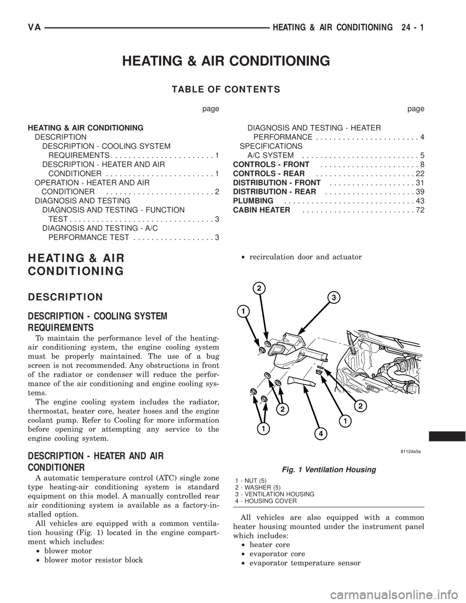
All vehicles are equipped with a common ventila-
tion housing (Fig. 1) located in the engine compart-
ment which includes:
²blower motor
²blower motor resistor block²recirculation door and actuator
All vehicles are also equipped with a common
heater housing mounted under the instrument panel
which includes:
²heater core
²evaporator core
²evaporator temperature sensor
Fig. 1 Ventilation Housing
1 - NUT (5)
2 - WASHER (5)
3 - VENTILATION HOUSING
4 - HOUSING COVER
VAHEATING & AIR CONDITIONING 24 - 1
Page 1130 of 1232
²expansion valve
²air outlet temperature sensor
²mode doors
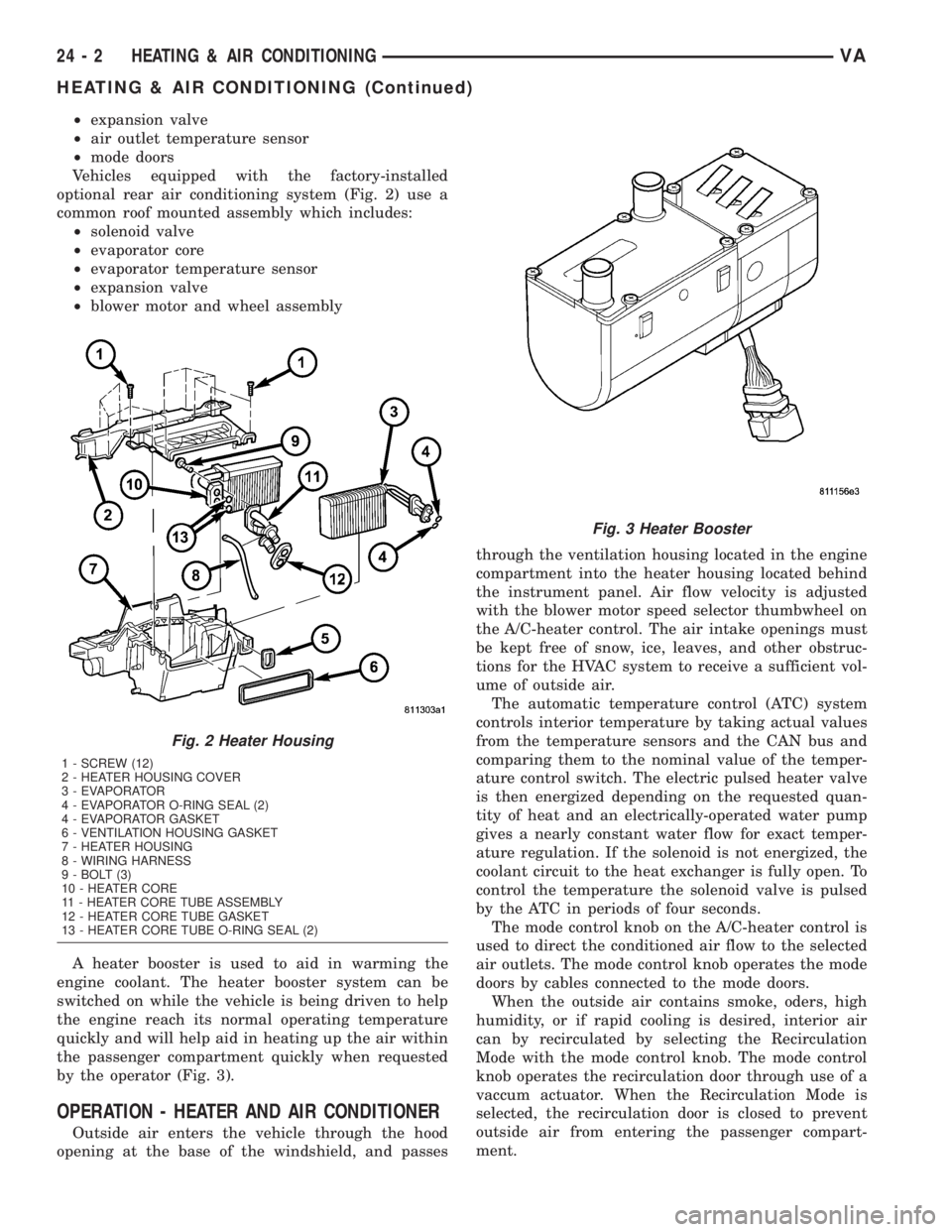
Vehicles equipped with the factory-installed
optional rear air conditioning system (Fig. 2) use a
common roof mounted assembly which includes:
²solenoid valve
²evaporator core
²evaporator temperature sensor
²expansion valve
²blower motor and wheel assembly
A heater booster is used to aid in warming the
engine coolant. The heater booster system can be
switched on while the vehicle is being driven to help
the engine reach its normal operating temperature
quickly and will help aid in heating up the air within
the passenger compartment quickly when requested
by the operator (Fig. 3).
OPERATION - HEATER AND AIR CONDITIONER
Outside air enters the vehicle through the hood
opening at the base of the windshield, and passesthrough the ventilation housing located in the engine
compartment into the heater housing located behind
the instrument panel. Air flow velocity is adjusted
with the blower motor speed selector thumbwheel on
the A/C-heater control. The air intake openings must
be kept free of snow, ice, leaves, and other obstruc-
tions for the HVAC system to receive a sufficient vol-
ume of outside air.
The automatic temperature control (ATC) system
controls interior temperature by taking actual values
from the temperature sensors and the CAN bus and
comparing them to the nominal value of the temper-
ature control switch. The electric pulsed heater valve
is then energized depending on the requested quan-
tity of heat and an electrically-operated water pump
gives a nearly constant water flow for exact temper-
ature regulation. If the solenoid is not energized, the
coolant circuit to the heat exchanger is fully open. To
control the temperature the solenoid valve is pulsed
by the ATC in periods of four seconds.
The mode control knob on the A/C-heater control is
used to direct the conditioned air flow to the selected
air outlets. The mode control knob operates the mode
doors by cables connected to the mode doors.
When the outside air contains smoke, oders, high
humidity, or if rapid cooling is desired, interior air
can by recirculated by selecting the Recirculation
Mode with the mode control knob. The mode control
knob operates the recirculation door through use of a
vaccum actuator. When the Recirculation Mode is
selected, the recirculation door is closed to prevent
outside air from entering the passenger compart-
ment.
Fig. 2 Heater Housing
1 - SCREW (12)
2 - HEATER HOUSING COVER
3 - EVAPORATOR
4 - EVAPORATOR O-RING SEAL (2)
4 - EVAPORATOR GASKET
6 - VENTILATION HOUSING GASKET
7 - HEATER HOUSING
8 - WIRING HARNESS
9 - BOLT (3)
10 - HEATER CORE
11 - HEATER CORE TUBE ASSEMBLY
12 - HEATER CORE TUBE GASKET
13 - HEATER CORE TUBE O-RING SEAL (2)
Fig. 3 Heater Booster
24 - 2 HEATING & AIR CONDITIONINGVA
HEATING & AIR CONDITIONING (Continued)
Page 1132 of 1232
c. With the engine running, duct temperature
should not be less than 2É C (35É F) or than 12É C
(54É F).
(7) If the compressor has not cycled off and the
duct temperature is less than 2É C (35É F) , check the
evaporator temperature sensor and circuit by per-
forming the ATC Function Test (Refer to 24 - HEAT-
ING & AIR CONDITIONING - DIAGNOSIS AND
TESTING).
(8) If duct output temperature is not within speci-
fications, check the refrigerant system for leaks and
proper refrigerant charge (Refer to 24 - HEATING &
AIR CONDITIONING/PLUMBING - DIAGNOSIS
AND TESTING) and (Refer to 24 - HEATING & AIR
CONDITIONING/PLUMBING - STANDARD PRO-
CEDURE).
DIAGNOSIS AND TESTING - HEATER
PERFORMANCE
Before performing the following tests, perform the
ATC Function Test using the DRBIIItand refer toCooling for the procedures to check the radiator cool-
ant level, serpentine drive belt tension, radiator air
flow and the radiator fan operation.
MAXIMUM HEATER OUTPUT
Engine coolant is provided to the heater core
through a heater valve and heater hose. With the
engine idling at normal operating temperature, set
the heater-A/C controls as follows:
²Temperature control in the full hot position
²Mode control in the floor heat position
²Blower motor control in the highest speed posi-
tion
Using a test thermometer, check the temperature
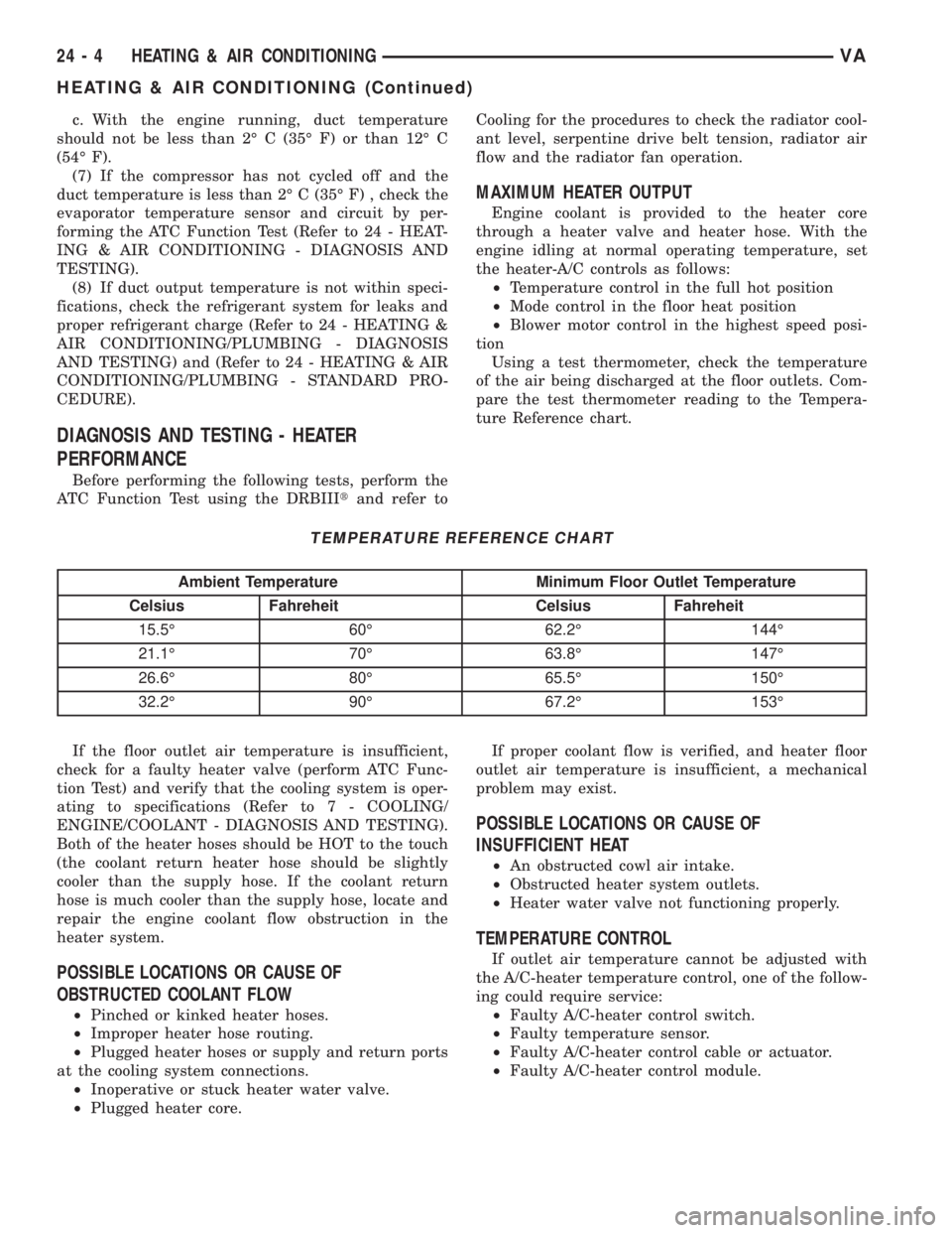
of the air being discharged at the floor outlets. Com-
pare the test thermometer reading to the Tempera-
ture Reference chart.
TEMPERATURE REFERENCE CHART
Ambient Temperature Minimum Floor Outlet Temperature
Celsius Fahreheit Celsius Fahreheit
15.5É 60É 62.2É 144É
21.1É 70É 63.8É 147É
26.6É 80É 65.5É 150É
32.2É 90É 67.2É 153É
If the floor outlet air temperature is insufficient,
check for a faulty heater valve (perform ATC Func-
tion Test) and verify that the cooling system is oper-
ating to specifications (Refer to 7 - COOLING/
ENGINE/COOLANT - DIAGNOSIS AND TESTING).
Both of the heater hoses should be HOT to the touch
(the coolant return heater hose should be slightly
cooler than the supply hose. If the coolant return
hose is much cooler than the supply hose, locate and
repair the engine coolant flow obstruction in the
heater system.
POSSIBLE LOCATIONS OR CAUSE OF
OBSTRUCTED COOLANT FLOW
²Pinched or kinked heater hoses.
²Improper heater hose routing.
²Plugged heater hoses or supply and return ports
at the cooling system connections.
²Inoperative or stuck heater water valve.
²Plugged heater core.If proper coolant flow is verified, and heater floor
outlet air temperature is insufficient, a mechanical
problem may exist.
POSSIBLE LOCATIONS OR CAUSE OF
INSUFFICIENT HEAT
²An obstructed cowl air intake.
²Obstructed heater system outlets.
²Heater water valve not functioning properly.
TEMPERATURE CONTROL
If outlet air temperature cannot be adjusted with
the A/C-heater temperature control, one of the follow-
ing could require service:
²Faulty A/C-heater control switch.
²Faulty temperature sensor.
²Faulty A/C-heater control cable or actuator.
²Faulty A/C-heater control module.
24 - 4 HEATING & AIR CONDITIONINGVA
HEATING & AIR CONDITIONING (Continued)