2005 MERCEDES-BENZ SPRINTER brake fluid
[x] Cancel search: brake fluidPage 68 of 1232
A worn, damaged wheel bearing or suspension
component are further causes of pull. A damaged
front tire (bruised, ply separation) can also cause
pull.
A common and frequently misdiagnosed pull condi-
tion is where direction of pull changes after a few
stops. The cause is a combination of brake drag fol-
lowed by fade at one of the brake units.
As the dragging brake overheats, efficiency is so
reduced that fade occurs. Since the opposite brake
unit is still functioning normally, its braking effect is
magnified. This causes pull to switch direction in
favor of the normally functioning brake unit.
An additional point when diagnosing a change in
pull condition concerns brake cool down. Remember
that pull will return to the original direction, if the
dragging brake unit is allowed to cool down (and is
not seriously damaged).
REAR BRAKE GRAB OR PULL
Rear grab or pull is usually caused by improperly
adjusted or seized parking brake cables, contami-
nated lining, bent or binding shoes and support
plates, or improperly assembled components. This is
particularly true when only one rear wheel is
involved. However, when both rear wheels are
affected, the master cylinder or proportioning valve
could be at fault.
BRAKES DO NOT HOLD AFTER DRIVING THROUGH DEEP
WATER PUDDLES
This condition is generally caused by water soaked
lining. If the lining is only wet, it can be dried by
driving with the brakes very lightly applied for a
mile or two. However, if the lining is both soaked and
dirt contaminated, cleaning and/or replacement will
be necessary.
BRAKE LINING CONTAMINATION
Brake lining contamination is mostly a product of
leaking calipers or worn seals, driving through deep
water puddles, or lining that has become covered
with grease and grit during repair. Contaminated lin-
ing should be replaced to avoid further brake prob-
lems.
WHEEL AND TIRE PROBLEMS
Some conditions attributed to brake components
may actually be caused by a wheel or tire problem.
A damaged wheel can cause shudder, vibration and
pull. A worn or damaged tire can also cause pull.
Severely worn tires with very little tread left can
produce a grab-like condition as the tire loses and
recovers traction. Flat-spotted tires can cause vibra-
tion and generate shudder during brake operation. A
tire with internal damage such as a severe bruise,
cut, or ply separation can cause pull and vibration.BRAKE NOISES
Some brake noise is common with rear drum
brakes and on some disc brakes during the first few
stops after a vehicle has been parked overnight or
stored. This is primarily due to the formation of trace
corrosion (light rust) on metal surfaces. This light
corrosion is typically cleared from the metal surfaces
after a few brake applications causing the noise to
subside.
BRAKE SQUEAK/SQUEAL
Brake squeak or squeal may be due to linings that
are wet or contaminated with brake fluid, grease, or
oil. Glazed linings and rotors with hard spots can
also contribute to squeak. Dirt and foreign material
embedded in the brake lining will also cause squeak/
squeal.
A very loud squeak or squeal is frequently a sign of
severely worn brake lining. If the lining has worn
through to the brake pads in spots, metal-to-metal
contact occurs. If the condition is allowed to continue,
rotors can become so scored that replacement is nec-
essary.
BRAKE CHATTER
Brake chatter is usually caused by loose or worn
components, or glazed/burnt lining. Rotors with hard
spots can also contribute to chatter. Additional causes
of chatter are out-of-tolerance rotors, brake lining not
securely attached to the shoes, loose wheel bearings
and contaminated brake lining.
THUMP/CLUNK NOISE
Thumping or clunk noises during braking are fre-
quentlynotcaused by brake components. In many
cases, such noises are caused by loose or damaged
steering, suspension, or engine components. However,
calipers that bind on the slide surfaces can generate
a thump or clunk noise.
STANDARD PROCEDURE
STANDARD PROCEDURE - MANUAL BLEEDING
Use Mopar brake fluid, or an equivalent quality
fluid meeting SAE and DOT 4 standards only. Use
fresh, clean fluid from a sealed container at all times.
(1) Remove reservoir filler caps and fill reservoir.
(2) If calipers, or wheel cylinders were overhauled,
open all caliper and wheel cylinder bleed screws.
Then close each bleed screw as fluid starts to drip
from it. Top off master cylinder reservoir once more
before proceeding.
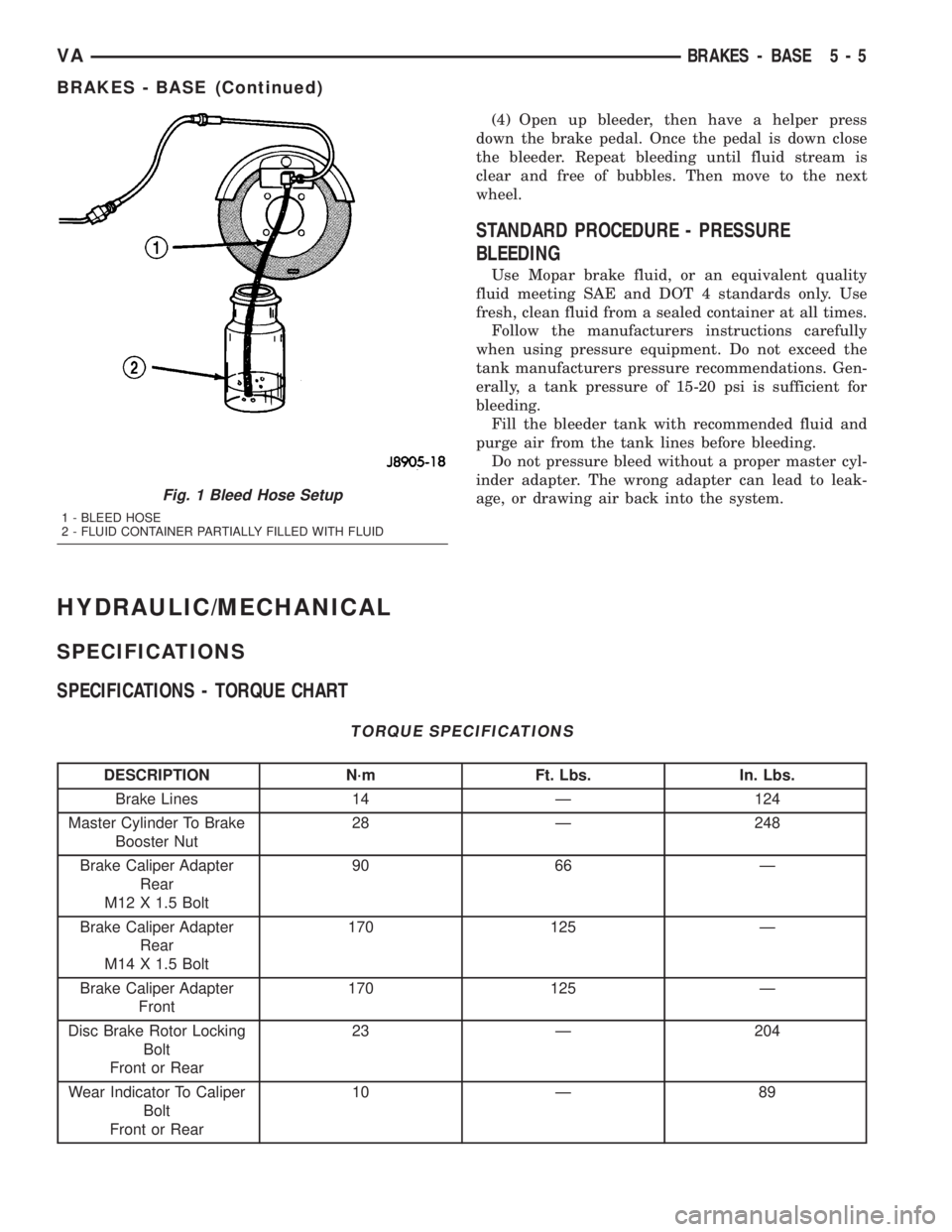
(3) Attach one end of bleed hose to bleed screw
and insert opposite end in glass container partially
filled with brake fluid (Fig. 1). Be sure end of bleed
hose is immersed in fluid.
5 - 4 BRAKES - BASEVA
BRAKES - BASE (Continued)
Page 69 of 1232
(4) Open up bleeder, then have a helper press
down the brake pedal. Once the pedal is down close
the bleeder. Repeat bleeding until fluid stream is
clear and free of bubbles. Then move to the next
wheel.
STANDARD PROCEDURE - PRESSURE
BLEEDING
Use Mopar brake fluid, or an equivalent quality
fluid meeting SAE and DOT 4 standards only. Use
fresh, clean fluid from a sealed container at all times.
Follow the manufacturers instructions carefully
when using pressure equipment. Do not exceed the
tank manufacturers pressure recommendations. Gen-
erally, a tank pressure of 15-20 psi is sufficient for
bleeding.
Fill the bleeder tank with recommended fluid and
purge air from the tank lines before bleeding.
Do not pressure bleed without a proper master cyl-
inder adapter. The wrong adapter can lead to leak-
age, or drawing air back into the system.
HYDRAULIC/MECHANICAL
SPECIFICATIONS
SPECIFICATIONS - TORQUE CHART
TORQUE SPECIFICATIONS
DESCRIPTION N´m Ft. Lbs. In. Lbs.
Brake Lines 14 Ð 124
Master Cylinder To Brake
Booster Nut28 Ð 248
Brake Caliper Adapter
Rear
M12 X 1.5 Bolt90 66 Ð
Brake Caliper Adapter
Rear
M14 X 1.5 Bolt170 125 Ð
Brake Caliper Adapter
Front170 125 Ð
Disc Brake Rotor Locking
Bolt
Front or Rear23 Ð 204
Wear Indicator To Caliper
Bolt
Front or Rear10 Ð 89
Fig. 1 Bleed Hose Setup
1 - BLEED HOSE
2 - FLUID CONTAINER PARTIALLY FILLED WITH FLUID
VABRAKES - BASE 5 - 5
BRAKES - BASE (Continued)
Page 73 of 1232
BRAKE PADS/SHOES
REMOVAL
REMOVAL - FRONT (SRW)
(1) Unscrew the cap from the brake fluid reservoir.
(2) Raise and support the vehicle.
(3) Remove the front wheels (Refer to 22 - TIRES/
WHEELS/WHEELS - REMOVAL).
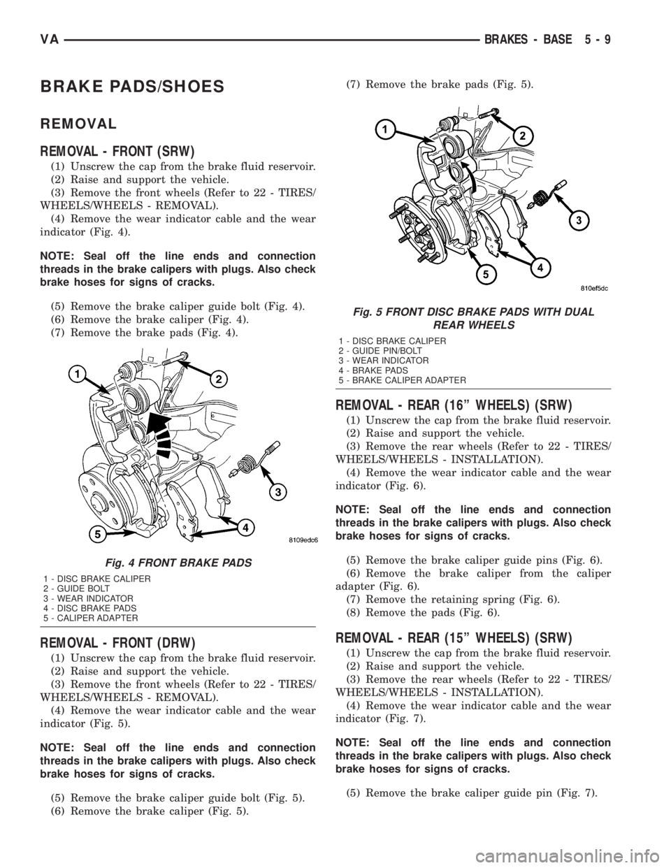
(4) Remove the wear indicator cable and the wear
indicator (Fig. 4).
NOTE: Seal off the line ends and connection
threads in the brake calipers with plugs. Also check
brake hoses for signs of cracks.
(5) Remove the brake caliper guide bolt (Fig. 4).
(6) Remove the brake caliper (Fig. 4).
(7) Remove the brake pads (Fig. 4).
REMOVAL - FRONT (DRW)
(1) Unscrew the cap from the brake fluid reservoir.
(2) Raise and support the vehicle.
(3) Remove the front wheels (Refer to 22 - TIRES/
WHEELS/WHEELS - REMOVAL).
(4) Remove the wear indicator cable and the wear
indicator (Fig. 5).
NOTE: Seal off the line ends and connection
threads in the brake calipers with plugs. Also check
brake hoses for signs of cracks.
(5) Remove the brake caliper guide bolt (Fig. 5).
(6) Remove the brake caliper (Fig. 5).(7) Remove the brake pads (Fig. 5).
REMOVAL - REAR (16º WHEELS) (SRW)
(1) Unscrew the cap from the brake fluid reservoir.
(2) Raise and support the vehicle.
(3) Remove the rear wheels (Refer to 22 - TIRES/
WHEELS/WHEELS - INSTALLATION).
(4) Remove the wear indicator cable and the wear
indicator (Fig. 6).
NOTE: Seal off the line ends and connection
threads in the brake calipers with plugs. Also check
brake hoses for signs of cracks.
(5) Remove the brake caliper guide pins (Fig. 6).
(6) Remove the brake caliper from the caliper
adapter (Fig. 6).
(7) Remove the retaining spring (Fig. 6).
(8) Remove the pads (Fig. 6).
REMOVAL - REAR (15º WHEELS) (SRW)
(1) Unscrew the cap from the brake fluid reservoir.
(2) Raise and support the vehicle.
(3) Remove the rear wheels (Refer to 22 - TIRES/
WHEELS/WHEELS - INSTALLATION).
(4) Remove the wear indicator cable and the wear
indicator (Fig. 7).
NOTE: Seal off the line ends and connection
threads in the brake calipers with plugs. Also check
brake hoses for signs of cracks.
(5) Remove the brake caliper guide pin (Fig. 7).
Fig. 4 FRONT BRAKE PADS
1 - DISC BRAKE CALIPER
2 - GUIDE BOLT
3 - WEAR INDICATOR
4 - DISC BRAKE PADS
5 - CALIPER ADAPTER
Fig. 5 FRONT DISC BRAKE PADS WITH DUAL
REAR WHEELS
1 - DISC BRAKE CALIPER
2 - GUIDE PIN/BOLT
3 - WEAR INDICATOR
4 - BRAKE PADS
5 - BRAKE CALIPER ADAPTER
VABRAKES - BASE 5 - 9
Page 74 of 1232
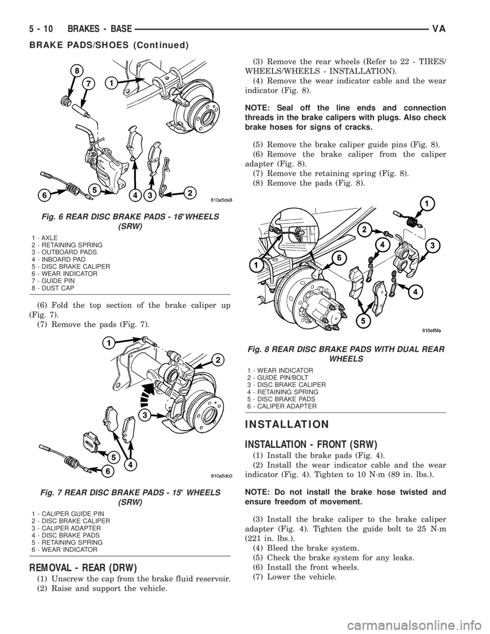
(6) Fold the top section of the brake caliper up
(Fig. 7).
(7) Remove the pads (Fig. 7).
REMOVAL - REAR (DRW)
(1) Unscrew the cap from the brake fluid reservoir.
(2) Raise and support the vehicle.(3) Remove the rear wheels (Refer to 22 - TIRES/
WHEELS/WHEELS - INSTALLATION).
(4) Remove the wear indicator cable and the wear
indicator (Fig. 8).
NOTE: Seal off the line ends and connection
threads in the brake calipers with plugs. Also check
brake hoses for signs of cracks.
(5) Remove the brake caliper guide pins (Fig. 8).
(6) Remove the brake caliper from the caliper
adapter (Fig. 8).
(7) Remove the retaining spring (Fig. 8).
(8) Remove the pads (Fig. 8).
INSTALLATION
INSTALLATION - FRONT (SRW)
(1) Install the brake pads (Fig. 4).
(2) Install the wear indicator cable and the wear
indicator (Fig. 4). Tighten to 10 N´m (89 in. lbs.).
NOTE: Do not install the brake hose twisted and
ensure freedom of movement.
(3) Install the brake caliper to the brake caliper
adapter (Fig. 4). Tighten the guide bolt to 25 N´m
(221 in. lbs.).
(4) Bleed the brake system.
(5) Check the brake system for any leaks.
(6) Install the front wheels.
(7) Lower the vehicle.
Fig. 6 REAR DISC BRAKE PADS - 16(WHEELS
(SRW)
1 - AXLE
2 - RETAINING SPRING
3 - OUTBOARD PADS
4 - INBOARD PAD
5 - DISC BRAKE CALIPER
6 - WEAR INDICATOR
7 - GUIDE PIN
8 - DUST CAP
Fig. 7 REAR DISC BRAKE PADS - 15(WHEELS
(SRW)
1 - CALIPER GUIDE PIN
2 - DISC BRAKE CALIPER
3 - CALIPER ADAPTER
4 - DISC BRAKE PADS
5 - RETAINING SPRING
6 - WEAR INDICATOR
Fig. 8 REAR DISC BRAKE PADS WITH DUAL REAR
WHEELS
1 - WEAR INDICATOR
2 - GUIDE PIN/BOLT
3 - DISC BRAKE CALIPER
4 - RETAINING SPRING
5 - DISC BRAKE PADS
6 - CALIPER ADAPTER
5 - 10 BRAKES - BASEVA
BRAKE PADS/SHOES (Continued)
Page 75 of 1232
INSTALLATION - FRONT (DRW)
(1) Install the brake pads (Fig. 5).
(2) Install the wear indicator cable and the wear
indicator (Fig. 5). Tighten to 10 N´m (89 in. lbs.).
NOTE: Do not install the brake hose twisted and
ensure freedom of movement.
(3) Install the brake caliper to the brake caliper
adapter (Fig. 5). Tighten the guide bolt to 25 N´m
(221 in. lbs.)(M8 bolt) or Tighten the guide bolt to 30
N´m (265 in. lbs.)(M10 10.9 bolt).
(4) Bleed the brake system.
(5) Check the brake system for any leaks.
(6) Install the front wheels.
(7) Lower the vehicle.
INSTALLATION - REAR (16º WHEELS) (SRW)
(1) Install the brake pads (Fig. 6).
(2) Install the wear indicator cable and the wear
indicator (Fig. 6). Tighten to 10 N´m (89 in. lbs.).
NOTE: Do not install the brake hose twisted and
ensure freedom of movement.
(3) Install the brake caliper to brake caliper
adapter (Fig. 6). Tighten the guide pins to 25 N´m
(221 in. lbs.) for M8 bolt or 30 N´m (266 in. lbs.) for
M10 bolt.
(4) Install the retaining spring (Fig. 6).
(5) Install the rear wheels (Refer to 22 - TIRES/
WHEELS/WHEELS - INSTALLATION).
(6) Lower the vehicle.
INSTALLATION - REAR (16º WHEELS) (SRW)
(1) Install the brake pads (Fig. 7).
(2) Install the wear indicator cable and the wear
indicator (Fig. 7). Tighten to 10 N´m (89 in. lbs.).
NOTE: Do not install the brake hose twisted and
ensure freedom of movement.
(3) Install the brake caliper to brake caliper
adapter (Fig. 7). Tighten the guide pin to 30 N´m
(266 in. lbs.) for M10 bolt.
(4) Install the rear wheels (Refer to 22 - TIRES/
WHEELS/WHEELS - INSTALLATION).
(5) Lower the vehicle.
INSTALLATION - REAR (DRW)
(1) Install the brake pads (Fig. 8).
(2) Install the wear indicator cable and the wear
indicator (Fig. 8). Tighten to 10 N´m (89 in. lbs.).
NOTE: Do not install the brake hose twisted and
ensure freedom of movement.(3) Install the brake caliper to brake caliper
adapter (Fig. 8). Tighten the guide pins to 25 N´m
(221 in. lbs.) for M8 bolt or 30 N´m (266 in. lbs.) for
M10 10.9 bolt.
(4) Install the retaining spring (Fig. 8).
(5) Install the rear wheels (Refer to 22 - TIRES/
WHEELS/WHEELS - INSTALLATION).
(6) Lower the vehicle.
DISC BRAKE CALIPERS
REMOVAL
REMOVAL - FRONT (SRW)
(1) Unscrew the cap from the brake fluid reservoir.
(2) Raise and support the vehicle.
(3) Remove the front wheels (Refer to 22 - TIRES/
WHEELS/WHEELS - REMOVAL).
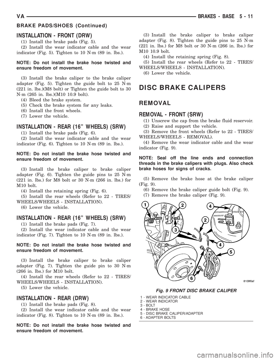
(4) Remove the wear indicator cable and the wear
indicator (Fig. 9).
NOTE: Seal off the line ends and connection
threads in the brake calipers with plugs. Also check
brake hoses for signs of cracks.
(5) Remove the brake hose at the brake caliper
(Fig. 9).
(6) Remove the brake caliper guide bolt (Fig. 9).
(7) Remove the brake caliper (Fig. 9).
Fig. 9 FRONT DISC BRAKE CALIPER
1 - WEAR INDICATOR CABLE
2 - WEAR INDICATOR
3 - BOLT
4 - BRAKE HOSE
5 - DISC BRAKE CALIPER/ADAPTER
6 - ADAPTER BOLTS
VABRAKES - BASE 5 - 11
BRAKE PADS/SHOES (Continued)
Page 76 of 1232
REMOVAL - FRONT (DRW)
(1) Unscrew the cap from the brake fluid reservoir.
(2) Raise and support the vehicle.
(3) Remove the front wheels (Refer to 22 - TIRES/
WHEELS/WHEELS - REMOVAL).
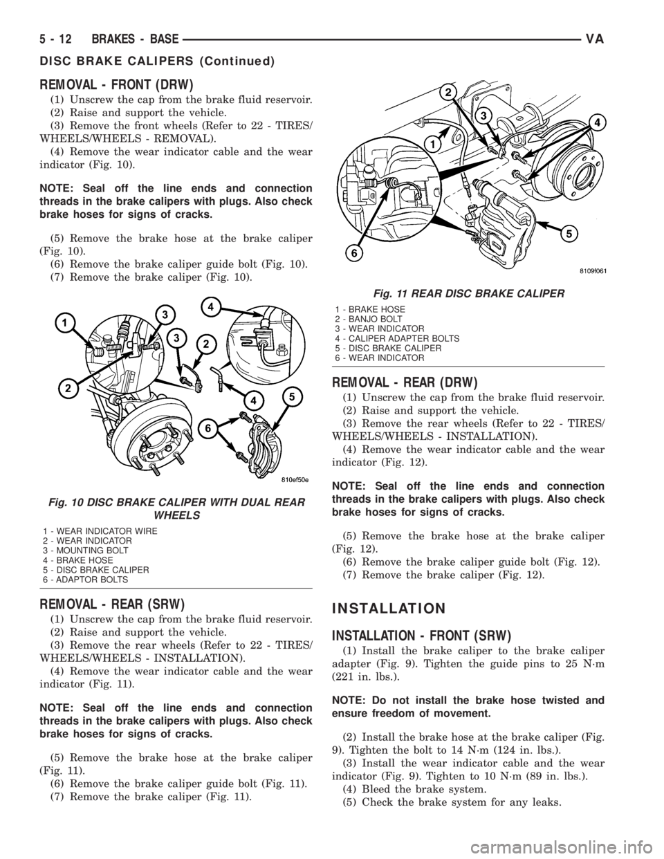
(4) Remove the wear indicator cable and the wear
indicator (Fig. 10).
NOTE: Seal off the line ends and connection
threads in the brake calipers with plugs. Also check
brake hoses for signs of cracks.
(5) Remove the brake hose at the brake caliper
(Fig. 10).
(6) Remove the brake caliper guide bolt (Fig. 10).
(7) Remove the brake caliper (Fig. 10).
REMOVAL - REAR (SRW)
(1) Unscrew the cap from the brake fluid reservoir.
(2) Raise and support the vehicle.
(3) Remove the rear wheels (Refer to 22 - TIRES/
WHEELS/WHEELS - INSTALLATION).
(4) Remove the wear indicator cable and the wear
indicator (Fig. 11).
NOTE: Seal off the line ends and connection
threads in the brake calipers with plugs. Also check
brake hoses for signs of cracks.
(5) Remove the brake hose at the brake caliper
(Fig. 11).
(6) Remove the brake caliper guide bolt (Fig. 11).
(7) Remove the brake caliper (Fig. 11).
REMOVAL - REAR (DRW)
(1) Unscrew the cap from the brake fluid reservoir.
(2) Raise and support the vehicle.
(3) Remove the rear wheels (Refer to 22 - TIRES/
WHEELS/WHEELS - INSTALLATION).
(4) Remove the wear indicator cable and the wear
indicator (Fig. 12).
NOTE: Seal off the line ends and connection
threads in the brake calipers with plugs. Also check
brake hoses for signs of cracks.
(5) Remove the brake hose at the brake caliper
(Fig. 12).
(6) Remove the brake caliper guide bolt (Fig. 12).
(7) Remove the brake caliper (Fig. 12).
INSTALLATION
INSTALLATION - FRONT (SRW)
(1) Install the brake caliper to the brake caliper
adapter (Fig. 9). Tighten the guide pins to 25 N´m
(221 in. lbs.).
NOTE: Do not install the brake hose twisted and
ensure freedom of movement.
(2) Install the brake hose at the brake caliper (Fig.
9). Tighten the bolt to 14 N´m (124 in. lbs.).
(3) Install the wear indicator cable and the wear
indicator (Fig. 9). Tighten to 10 N´m (89 in. lbs.).
(4) Bleed the brake system.
(5) Check the brake system for any leaks.
Fig. 10 DISC BRAKE CALIPER WITH DUAL REAR
WHEELS
1 - WEAR INDICATOR WIRE
2 - WEAR INDICATOR
3 - MOUNTING BOLT
4 - BRAKE HOSE
5 - DISC BRAKE CALIPER
6 - ADAPTOR BOLTS
Fig. 11 REAR DISC BRAKE CALIPER
1 - BRAKE HOSE
2 - BANJO BOLT
3 - WEAR INDICATOR
4 - CALIPER ADAPTER BOLTS
5 - DISC BRAKE CALIPER
6 - WEAR INDICATOR
5 - 12 BRAKES - BASEVA
DISC BRAKE CALIPERS (Continued)
Page 77 of 1232
(6) Install the front wheels.
(7) Lower the vehicle.
INSTALLATION - FRONT (DRW)
(1) Install the brake caliper to the brake caliper
adapter (Fig. 10). Tighten the guide pins to 25 N´m
(221 in. lbs.)(M8 bolt) or Tighten the guide pins to 30
N´m (265 in. lbs.)(M10 10.9 bolt).
NOTE: Do not install the brake hose twisted and
ensure freedom of movement.
(2) Install the brake hose at the brake caliper (Fig.
10). Tighten the bolt to 14 N´m (124 in. lbs.).
(3) Install the wear indicator cable and the wear
indicator (Fig. 10). Tighten to 10 N´m (89 in. lbs.).
(4) Bleed the brake system.
(5) Check the brake system for any leaks.
(6) Install the front wheels.
(7) Lower the vehicle.
INSTALLATION - REAR (SRW)
(1) Install the brake caliper to brake caliper
adapter (Fig. 11). Tighten the guide bolt to 25 N´m
(221 in. lbs.) for M8 bolt or 30 N´m (266 in. lbs.) for
M10 bolt.
NOTE: Do not install the brake hose twisted and
ensure freedom of movement.
(2) Install the brake hose at the brake caliper (Fig.
11). Tighten the bolt to 14 N´m (124 in. lbs.).(3) Install the wear indicator cable and the wear
indicator (Fig. 11). Tighten to 10 N´m (89 in. lbs.).
(4) Bleed the brake system.
(5) Check the brake system for any leaks.
(6) Install the rear wheels (Refer to 22 - TIRES/
WHEELS/WHEELS - INSTALLATION).
(7) Lower the vehicle.
INSTALLATION - REAR (DRW)
(1) Install the brake caliper to brake caliper
adapter (Fig. 12). Tighten the guide bolt to 25 N´m
(221 in. lbs.) for M8 bolt or 30 N´m (266 in. lbs.) for
M10 bolt.
NOTE: Do not install the brake hose twisted and
ensure freedom of movement.
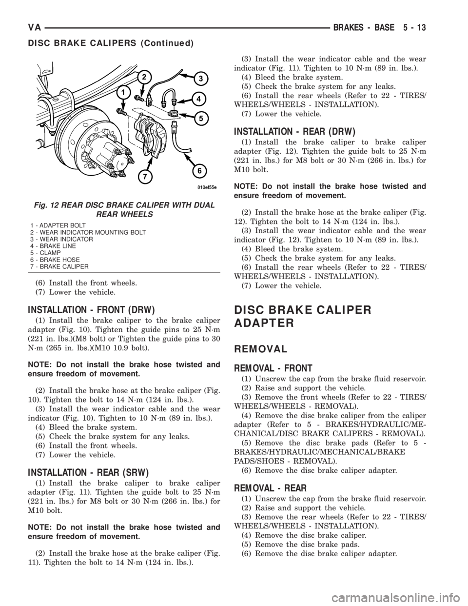
(2) Install the brake hose at the brake caliper (Fig.
12). Tighten the bolt to 14 N´m (124 in. lbs.).
(3) Install the wear indicator cable and the wear
indicator (Fig. 12). Tighten to 10 N´m (89 in. lbs.).
(4) Bleed the brake system.
(5) Check the brake system for any leaks.
(6) Install the rear wheels (Refer to 22 - TIRES/
WHEELS/WHEELS - INSTALLATION).
(7) Lower the vehicle.
DISC BRAKE CALIPER
ADAPTER
REMOVAL
REMOVAL - FRONT
(1) Unscrew the cap from the brake fluid reservoir.
(2) Raise and support the vehicle.
(3) Remove the front wheels (Refer to 22 - TIRES/
WHEELS/WHEELS - REMOVAL).
(4) Remove the disc brake caliper from the caliper
adapter (Refer to 5 - BRAKES/HYDRAULIC/ME-
CHANICAL/DISC BRAKE CALIPERS - REMOVAL).
(5) Remove the disc brake pads (Refer to 5 -
BRAKES/HYDRAULIC/MECHANICAL/BRAKE
PADS/SHOES - REMOVAL).
(6) Remove the disc brake caliper adapter.
REMOVAL - REAR
(1) Unscrew the cap from the brake fluid reservoir.
(2) Raise and support the vehicle.
(3) Remove the rear wheels (Refer to 22 - TIRES/
WHEELS/WHEELS - INSTALLATION).
(4) Remove the disc brake caliper.
(5) Remove the disc brake pads.
(6) Remove the disc brake caliper adapter.
Fig. 12 REAR DISC BRAKE CALIPER WITH DUAL
REAR WHEELS
1 - ADAPTER BOLT
2 - WEAR INDICATOR MOUNTING BOLT
3 - WEAR INDICATOR
4 - BRAKE LINE
5 - CLAMP
6 - BRAKE HOSE
7 - BRAKE CALIPER
VABRAKES - BASE 5 - 13
DISC BRAKE CALIPERS (Continued)
Page 78 of 1232
INSTALLATION
INSTALLATION - FRONT
(1) Install the brake caliper adapter to the steering
knuckle. Tighten to 170 N´m (125 ft. lbs.).
(2) Install the disc brake shoes (Refer to 5 -
BRAKES/HYDRAULIC/MECHANICAL/BRAKE
PADS/SHOES - INSTALLATION).
NOTE: Do not install the brake hose twisted and
ensure freedom of movement.
(3) Install the disc brake caliper. Tighten the bolt
to 14 N´m (124 in. lbs.) (Refer to 5 - BRAKES/HY-
DRAULIC/MECHANICAL/DISC BRAKE CALIPERS
- INSTALLATION).
(4) Install the front wheels (Refer to 22 - TIRES/
WHEELS/WHEELS - INSTALLATION).
(5) Lower the vehicle.
INSTALLATION - REAR
(1) Install the brake caliper adapter to the axle
mount. Tighten to 90 N´m (66 ft. lbs.) for M12X1.5
bolt or 170 N´m (125 ft. lbs.) for M14X1.5 bolt.
(2) Install the disc brake pads (Refer to 5 -
BRAKES/HYDRAULIC/MECHANICAL/BRAKE
PADS/SHOES - INSTALLATION).
NOTE: Do not install the brake hose twisted and
ensure freedom of movement.
(3) Install the disc brake caliper (Refer to 5 -
BRAKES/HYDRAULIC/MECHANICAL/DISC
BRAKE CALIPERS - INSTALLATION).
(4) Install the rear wheels (Refer to 22 - TIRES/
WHEELS/WHEELS - INSTALLATION).
(5) Lower the vehicle.
FLUID
DIAGNOSIS AND TESTING - BRAKE FLUID
CONTAMINATION
Indications of fluid contamination are swollen or
deteriorated rubber parts.
Swollen rubber parts indicate the presence of
petroleum in the brake fluid.
To test for contamination, put a small amount of
drained brake fluid in clear glass jar. If fluid sepa-
rates into layers, there is mineral oil or other fluid
contamination of the brake fluid.
If brake fluid is contaminated, drain and thor-
oughly flush system. Replace master cylinder, ALB
Controller, caliper seals, Antilock Brakes hydraulic
unit and all hydraulic fluid hoses.
STANDARD PROCEDURE - BRAKE FLUID
LEVEL
Always clean the master cylinder reservoir and
caps before checking fluid level. If not cleaned, dirt
could enter the fluid.
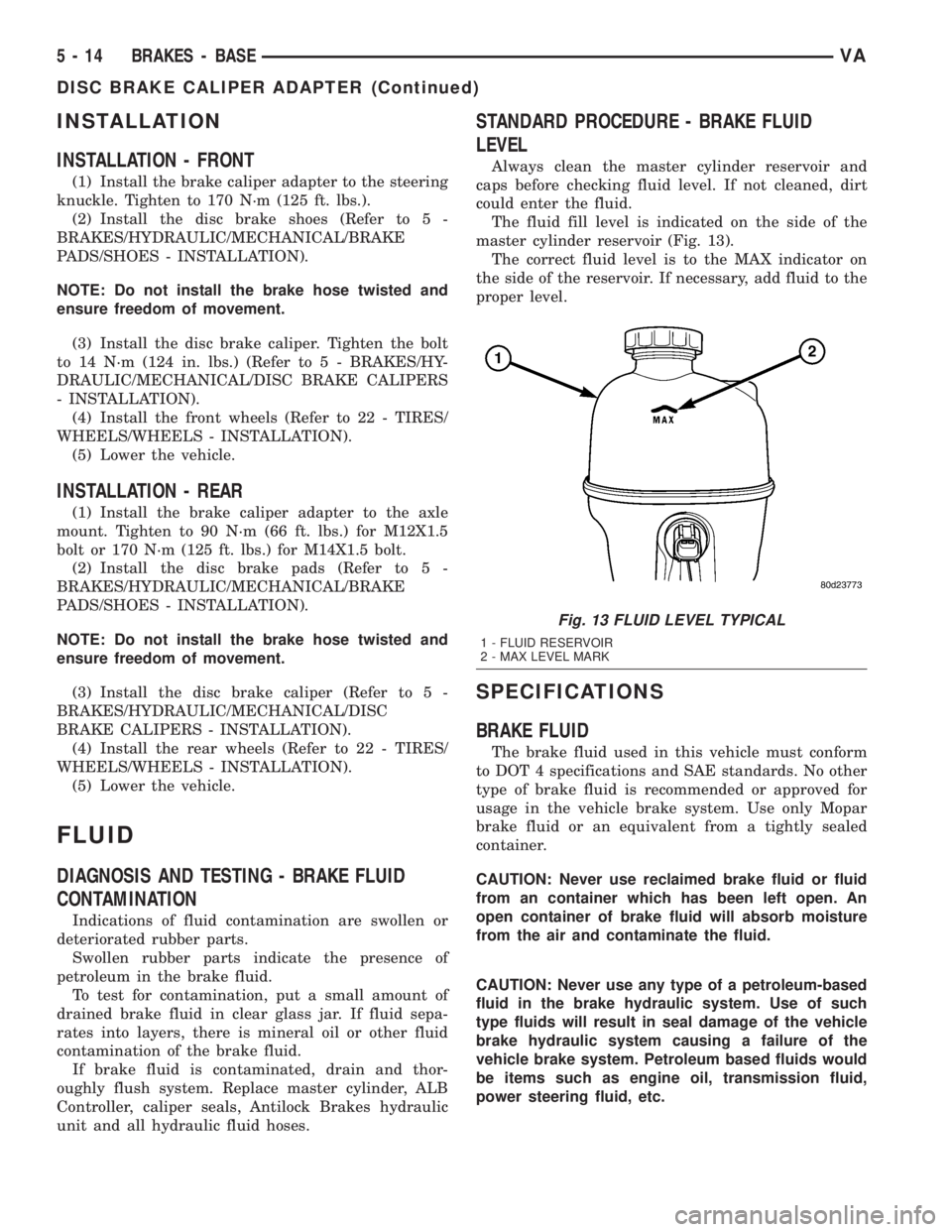
The fluid fill level is indicated on the side of the
master cylinder reservoir (Fig. 13).
The correct fluid level is to the MAX indicator on
the side of the reservoir. If necessary, add fluid to the
proper level.
SPECIFICATIONS
BRAKE FLUID
The brake fluid used in this vehicle must conform
to DOT 4 specifications and SAE standards. No other
type of brake fluid is recommended or approved for
usage in the vehicle brake system. Use only Mopar
brake fluid or an equivalent from a tightly sealed
container.
CAUTION: Never use reclaimed brake fluid or fluid
from an container which has been left open. An
open container of brake fluid will absorb moisture
from the air and contaminate the fluid.
CAUTION: Never use any type of a petroleum-based
fluid in the brake hydraulic system. Use of such
type fluids will result in seal damage of the vehicle
brake hydraulic system causing a failure of the
vehicle brake system. Petroleum based fluids would
be items such as engine oil, transmission fluid,
power steering fluid, etc.
Fig. 13 FLUID LEVEL TYPICAL
1 - FLUID RESERVOIR
2 - MAX LEVEL MARK
5 - 14 BRAKES - BASEVA
DISC BRAKE CALIPER ADAPTER (Continued)