Page 508 of 969
A86599
8.0 (80, 71 in.Vlbf)
Ignition Coil Assy
Cylinder Head Cover Sub-assy LH
8.4 (85, 74 in.Vlbf)
Engine Wire
Cylinder Head Cover Gasket No. 2
Camshaft Bearing
Cap No. 2
16 (163, 12)
Camshaft Bearing Cap No. 2Camshaft Bearing Cap No. 3
Camshaft Bearing
Cap No. 6 Camshaft Bearing Cap No. 5
Camshaft Bearing Cap No. 4
Camshaft Bearing Cap No. 2
16 (163, 12)
Camshaft Bearing Cap No. 1
No. 4 Camshaft Sub-assy
N´m (kgf´cm, ft´lbf)
: Specified torque� Non-reusable part
8.0 (80, 71 in.Vlbf)
Camshaft Setting
Oil Seal �
19 (189, 14)
� Cylinder Head
Gasket No. 2
1st: 54 (550, 40)
2st: Turn 90� See page 14-133
5.4 (55, 48 in.Vlbf)
5.4 (55, 48 in.Vlbf)
No. 3 Camshaft Sub-assy
Water Inlet Pipe
20 (199, 14)
� O-ring
Cylinder Head LH
x9
x10
x8 x10 14-132
- ENGINE MECHANICALCYLINDER HEAD GASKET NO.2 (3MZ-FE)
2224 Author�: Date�:
2005 LEXUS ES330 REPAIR MANUAL (RM1124U)
Page 511 of 969

14-135
2227 Author�: Date�:
2005 LEXUS ES330 REPAIR MANUAL (RM1124U)
43.")
A78719
1
2
3
4
5
67
8
Front
A78730
90�
Front
Painted Mark
A78718
Front
- ENGINE MECHANICALCYLINDER HEAD GASKET NO.2 (3MZ-FE)
14-135
2227 Author�: Date�:
2005 LEXUS ES330 REPAIR MANUAL (RM1124U)
43. INSTALL CYLINDER HEAD LH
NOTICE:
The cylinder head bolts are tightened in 2 successive
steps.
(a) Apply a light coat of engine oil to the threads of the cylin-
der head bolts.
(b) Install the plate washer to the cylinder head bolt.
(c) Using several steps, install and tighten the 8 cylinder
head bolts uniformly in the sequence shown in the illustra-
tion.
Torque: 54 NVm (550 kgfVcm, 40 ftVlbf)
(d) Mark the front side of each cylinder head bolt head with
paint as shown in the illustration.
(e) Retighten the cylinder head bolts by 90�in the same se-
quence as step (c).
(f) Check that each painted mark is now at a 90� angle to the
front.
(g) Using a socket hexagon wrench 8, install the hexagon
bolt.
Torque: 19 NVm (189 kgfVcm, 14 ftVlbf)
(h) Install the wire harness clamp bracket with the bolt.
Torque: 5.4 NVm (55 kgfVcm, 48 in.Vlbf)
(i) Connect the ground cable with the bolt.
Torque: 5.4 NVm (55 kgfVcm, 48 in.Vlbf)
44. INSTALL NO.4 CAMSHAFT SUB-ASSY (See page 14-107)
45. INSTALL NO.3 CAMSHAFT SUB-ASSY (See page 14-107)
46. INSTALL CYLINDER HEAD COVER SUB-ASSY LH (See page 14-7)
47. INSTALL IGNITION COIL ASSY (See page 14-7)
48. INSTALL WATER INLET PIPE (See page 16-16)
Page 512 of 969

2228 Author�: Date�:
2005 LEXUS ES330 REPAIR MANUAL (RM1124U)
49. INSTALL OIL LEVEL GAGE GUIDE
(a) Install a new O-ring to")
A86573
O-ring
14-136
- ENGINE MECHANICALCYLINDER HEAD GASKET NO.2 (3MZ-FE)
2228 Author�: Date�:
2005 LEXUS ES330 REPAIR MANUAL (RM1124U)
49. INSTALL OIL LEVEL GAGE GUIDE
(a) Install a new O-ring to the oil level gage guide.
(b) Apply soapy water to the O-ring.
(c) Push in the oil level gage guide end into the guide hole of
the cylinder block.
(d) Install the oil level gage guide with the bolt.
Torque: 8.0 NVm (82 kgfVcm, 71 in.Vlbf)
(e) Install the oil level gage.
50. INSTALL EXHAUST PIPE ASSY FRONT (See page 15-2)
51. INSTALL MANIFOLD STAY NO.2 (See page 14-29)
52. INSTALL TIMING BELT NO.3 COVER (See page 14-93)
53. INSTALL CAMSHAFT TIMING PULLEY (See page 14-93)
SST 09960-10010 (09962-01000, 09963-01000), 09249-63010
54. INSTALL TIMING BELT IDLER SUB-ASSY NO.2 (See page 14-93)
55. INSPECT TIMING BELT (See page 14-79)
56. INSTALL TIMING BELT (See page 14-79)
SST 09960-10010 (09962-01000, 09963-01000)
57. INSTALL TIMING BELT TENSIONER ASSY (See page 14-79)
58. INSTALL TIMING BELT GUIDE NO.2 (See page 14-79)
59. INSTALL ENGINE MOUNTING BRACKET RH (See page 14-79)
60. INSTALL TIMING BELT NO.2 COVER (See page 14-79)
61. INSTALL TIMING BELT NO.1 COVER (See page 14-79)
62. INSTALL CRANKSHAFT PULLEY (See page 14-79)
SST 09213-54015 (91651-60855), 09330-00021
63. INSTALL GENERATOR BRACKET NO.2 (See page 14-79)
64. INSTALL ENGINE MOUNTING STAY NO.2 RH (See page 14-79)
65. INSTALL ENGINE MOVING CONTROL ROD (See page 14-79)
66. INSTALL VANE PUMP V BELT (See page 14-5)
67. INSTALL V (COOLER COMPRESSOR TO CRANKSHAFT PULLEY) BELT NO.1
(See page 14-5)
68. INSPECT DRIVE BELT DEFLECTION AND TENSION (See page 14-1)
69. INSTALL WATER OUTLET (See page 10-16)
70. INSTALL INTAKE MANIFOLD (See page 10-16)
71. INSTALL INTAKE AIR SURGE TANK (See page 11-13)
72. INSTALL EMISSION CONTROL VALVE SET (See page 11-13)
73. INSTALL AIR CLEANER CASE (See page 19-5)
74. INSTALL AIR CLEANER CAP SUB-ASSY (See page 10-1 1)
75. INSTALL AIR CLEANER INLET ASSY (See page 19-5)
76. CHECK CONNECTION OF VACUUM HOSE (See page 14-29)
77. INSTALL V-BANK COVER SUB-ASSY (See page 10-1 1)
78. INSTALL FRONT SUSPENSION UPPER BRACE CENTER (W/O TEMS) (See page 10-1 1)
79. INSTALL FRONT WHEEL RH (See page 14-5)
80. ADD ENGINE OIL (See page 17-20)
81. ADD ENGINE COOLANT (See page 16-9)
82. CHECK FOR ENGINE OIL LEAKS
83. CHECK FOR ENGINE COOLANT LEAKS (See page 16-1)
84. INSPECT FOR FUEL LEAKS
Page 515 of 969

14-139
2231 Author�: Date�:
2005 LEXUS ES330 REPAIR MANUAL (RM1124U)
16. INSTALL OIL PUMP SEAL
(a) Apply multi-purpose greas")
A78766
SST
A78746
Inward
Sensor
- ENGINE MECHANICALOIL PUMP SEAL (3MZ-FE)
14-139
2231 Author�: Date�:
2005 LEXUS ES330 REPAIR MANUAL (RM1124U)
16. INSTALL OIL PUMP SEAL
(a) Apply multi-purpose grease to a new oil seal lip.
NOTICE:
Keep the lip free of foreign objects.
(b) Using SST and a hammer, tap in the new oil seal until its
surface is flush with the oil pump edge.
SST 09223-00010
NOTICE:
�Be careful not to tap the oil seal at an angle.
�Wipe off extra grease on the crankshaft.
17. INSTALL CRANKSHAFT TIMING PULLEY
(a) Align the keyway of the pulley with the key located on the
crankshaft, then slide the pulley into place.
NOTICE:
Do not scratch the sensor area of the crankshaft timing
pulley.
(b) Install the timing belt plate with the bolt.
Torque: 8.0 NVm (82 kgfVcm, 71 in.Vlbf)
18. INSPECT TIMING BELT (See page 14-79)
19. INSTALL TIMING BELT (See page 14-79)
SST 09960-10010 (09962-01000, 09963-01000)
20. INSTALL TIMING BELT TENSIONER ASSY (See page 14-79)
21. INSTALL TIMING BELT GUIDE NO.2 (See page 14-79)
22. INSTALL ENGINE MOUNTING BRACKET RH (See page 14-79)
23. INSTALL TIMING BELT NO.2 COVER (See page 14-79)
24. INSTALL TIMING BELT NO.1 COVER (See page 14-79)
25. INSTALL CRANKSHAFT PULLEY (See page 14-79)
SST 09213-54015 (91651-60855), 09330-00021
26. INSTALL GENERATOR BRACKET NO.2 (See page 14-79)
27. INSTALL ENGINE MOUNTING STAY NO.2 RH (See page 14-79)
28. INSTALL ENGINE MOVING CONTROL ROD (See page 14-79)
29. INSTALL VANE PUMP V BELT (See page 14-5)
30. INSTALL V (COOLER COMPRESSOR TO CRANKSHAFT PULLEY) BELT NO.1
(See page 14-5)
31. INSPECT DRIVE BELT DEFLECTION AND TENSION (See page 14-1)
32. INSTALL FRONT WHEEL RH (See page 14-5)
33. CHECK FOR ENGINE OIL LEAKS
Page 517 of 969
A78771
1
2
34
5
6
7
8
- ENGINE MECHANICALENGINE REAR OIL SEAL (3MZ-FE)
14-141
2233 Author�: Date�:
2005 LEXUS ES330 REPAIR MANUAL (RM1124U)
(e) Using several steps, install and tighten the 8 bolts uni-
formly in the sequence shown in the illustration.
Torque: 83 NVm (846 kgfVcm, 61 ftVlbf)
NOTICE:
Do not start the engine within 1 hour after installing.
6. INSTALL AUTOMATIC TRANSAXLE ASSY (See page 40-9)
Page 518 of 969
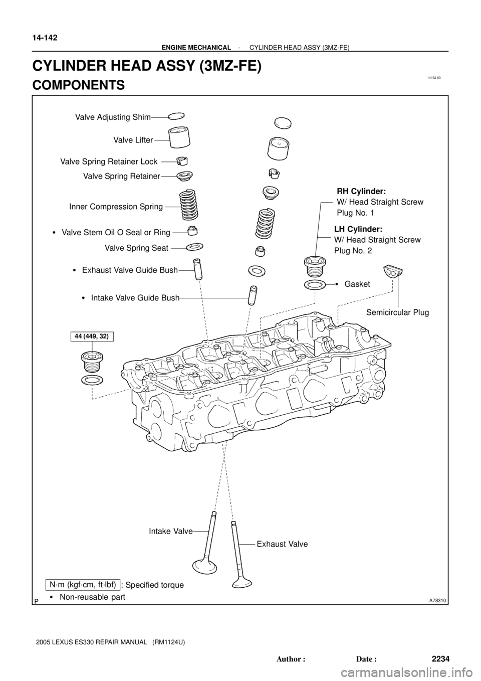
1419J-03
A78310� Non-reusable part
N´m (kgf´cm, ft´lbf)
: Specified torque Valve Lifter
Valve Spring Retainer Lock
Valve Spring Retainer
Inner Compression Spring
� Exhaust Valve Guide Bush � Valve Stem Oil O Seal or Ring
Valve Spring Seat
� Intake Valve Guide Bush
Exhaust Valve Intake Valve
Valve Adjusting Shim
RH Cylinder:
W/ Head Straight Screw
Plug No. 1
LH Cylinder:
W/ Head Straight Screw
Plug No. 2
� Gasket
Semicircular Plug
44 (449, 32)
14-142
- ENGINE MECHANICALCYLINDER HEAD ASSY (3MZ-FE)
2234 Author�: Date�:
2005 LEXUS ES330 REPAIR MANUAL (RM1124U)
CYLINDER HEAD ASSY (3MZ-FE)
COMPONENTS
Page 526 of 969

8 mm (0.31 in.)
A78783
LH Cylinder:
10 mm (0.39 in.)
8 mm (0.31 in.) 14-150
- ENGINE MECHANICALCYLINDER HEAD ASSY (3MZ-FE)
2242 Author�: Date�:
2005")
A05239
A05240
A78782
RH Cylinder:
10 mm (0.39 in.)
8 mm (0.31 in.)
A78783
LH Cylinder:
10 mm (0.39 in.)
8 mm (0.31 in.) 14-150
- ENGINE MECHANICALCYLINDER HEAD ASSY (3MZ-FE)
2242 Author�: Date�:
2005 LEXUS ES330 REPAIR MANUAL (RM1124U)
(d) Lay a strip of Plastigage across each of the camshaft jour-
nals.
(e) Install the bearing caps.
Torque: 16 NVm (163 kgfVcm, 12 ftVlbf)
NOTICE:
Do not turn the camshaft.
(f) Remove the bearing caps.
(g) Measure the Plastigage at its widest point.
Standard oil clearance:
Intake #4, #5 journals
0.025 to 0.057 mm (0.0010 to 0.0022 in.)
Other journals 0.025 to 0.062 mm (0.0010 to 0.0024 in.)
Maximum oil clearance 0.10 mm (0.0039 in.)
�If the oil clearance is greater than maximum, re-
place the camshaft.
�If necessary, replace the bearing caps and cylinder
head together.
NOTICE:
Completely remove the Plastigage.
24. INSTALL RING W/HEAD PIN (RH CYLINDER)
(a) Using a plastic-faced hammer, tap in a new ring pin to the
specified protrusion height.
Protrusion height: 3 mm (0.12 in.)
25. INSTALL RING PIN (LH CYLINDER)
(a) Using a plastic-faced hammer, tap in a new ring pin to the
specified protrusion height.
Protrusion height: 3 mm (0.12 in.)
Page 528 of 969
A78787
RH Cylinder:
49 mm
(1.93 in.)
M8
A78788
LH Cylinder:
49 mm
(1.93 in.)
M8
A78789
Intake: Exhaust:
Light Brown
Gray
A78790
SST 14-152
- ENGINE MECHANICALCYLINDER HEAD ASSY (3MZ-FE)
2244 Author�: Date�:
2005 LEXUS ES330 REPAIR MANUAL (RM1124U)
28. INSTALL STUD BOLT
(a) Install the stud bolts on the intake side.
Torque: 7.5 NVm (76 kgfVcm, 66 in.Vlbf)
29. INSTALL STUD BOLT
(a) Install the stud bolts on the exhaust side.
Torque: 15 NVm (153 kgfVcm, 11 ftVlbf)
30. INSTALL VALVE STEM OIL O SEAL OR RING
(a) Apply a light coat of engine oil to the valve stem.
NOTICE:
Installing the oil seals for intake and exhaust to the oppo-
site valve guide bush may cause an improper installation.
HINT:
The intake valve oil seal is light brown and the exhaust valve oil
seal is gray.
(b) Using SST, push in a new oil seal.
SST 09201-41020
NOTICE:
Failure to use SST will cause the seal to be damaged or im-
properly seated.

Ignition Coil Assy
Cylinder Head Cover Sub-assy LH
8.4 (85, 74 in.Vlbf)
Engine Wire
Cylinder Head Cover Gasket No. 2
Camshaft Bearing
Cap No. 2
16 (163, 12)
Camshaft Beari")