Page 590 of 969
110XU-01
A86358N´m (kgf´cm, ft´lbf) : Specified torque
7.9 (81, 70 in.Vlbf)x3
V-bank Cover Sub-assy
Mass Air Flow
Meter Connector Fuel Vapor Feed Hose
Assy
Vacuum Hose
Air Cleaner Cap
Sub-assy
Air Cleaner Filter
Element Sub-assy
5.0 (51, 44 in.Vlbf)
W/O TEMS:
Front Suspension Upper Brace Center
80 (816, 59)
Spacer
x2
Vacuum Hose
80 (816, 59)x2
Spacer
11-10
- FUELFUEL INJECTOR ASSY (3MZ-FE)
2038 Author�: Date�:
2005 LEXUS ES330 REPAIR MANUAL (RM1124U)
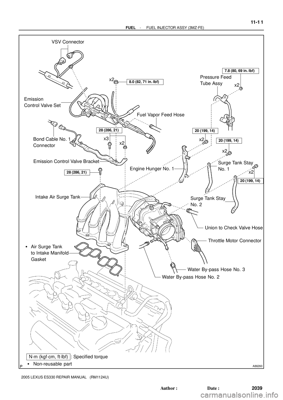
FUEL INJECTOR ASSY (3MZ-FE)
COMPONENTS
Page 591 of 969
A86260� Non-reusable part
: Specified torque VSV Connector
8.0 (82, 71 in.Vlbf)x2
Emission
Control Valve Set
Emission Control Valve Bracket
Intake Air Surge Tank
� Air Surge Tank
to Intake Manifold
Gasket
Throttle Motor Connector
Water By-pass Hose No. 3
Water By-pass Hose No. 2
N´m (kgf´cm, ft´lbf)
Union to Check Valve Hose
Fuel Vapor Feed Hose
x2 x3
Engine Hunger No. 1Surge Tank Stay
No. 1
Surge Tank Stay
No. 2
20 (199, 14)
20 (199, 14)
20 (199, 14)
7.8 (80, 69 in.Vlbf)
x2
x2 Pressure Feed
Tube Assy
28 (286, 21)
x2
x2
Bond Cable No. 1
Connector
28 (286, 21)
- FUELFUEL INJECTOR ASSY (3MZ-FE)
11-1 1
2039 Author�: Date�:
2005 LEXUS ES330 REPAIR MANUAL (RM1124U)
Page 592 of 969
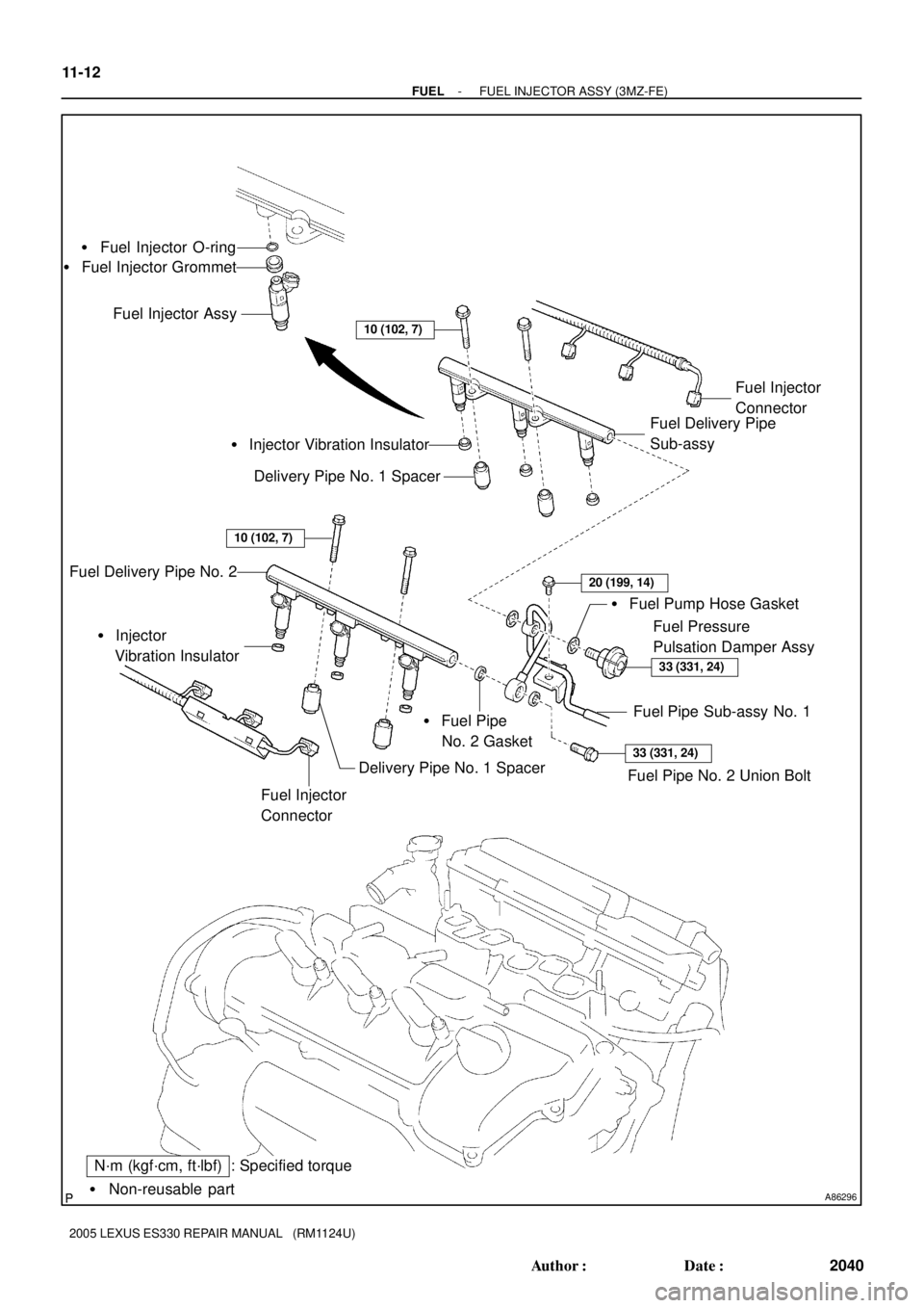
A86296� Non-reusable part
: Specified torqueN´m (kgf´cm, ft´lbf) � Fuel Injector O-ring
� Fuel Injector Grommet
Fuel Injector Assy
Fuel Delivery Pipe
Sub-assyFuel Injector
Connector
� Injector Vibration Insulator
Fuel Pressure
Pulsation Damper Assy � Fuel Pump Hose Gasket
� Fuel Pipe
No. 2 Gasket Delivery Pipe No. 1 Spacer
Delivery Pipe No. 1 Spacer Fuel Delivery Pipe No. 2
Fuel Injector
Connector � Injector
Vibration Insulator
Fuel Pipe Sub-assy No. 1
33 (331, 24)
20 (199, 14)
33 (331, 24)
10 (102, 7)
10 (102, 7)
Fuel Pipe No. 2 Union Bolt
11-12
- FUELFUEL INJECTOR ASSY (3MZ-FE)
2040 Author�: Date�:
2005 LEXUS ES330 REPAIR MANUAL (RM1124U)
Page 596 of 969

2044 Author�: Date�:
2005 LEXUS ES330 REPAIR MANUAL (RM1124U)
(e) Install 6 new insulators and the 4 delivery pipe No. 1
spacers to the intake mani")
A86305Turn 11-16
- FUELFUEL INJECTOR ASSY (3MZ-FE)
2044 Author�: Date�:
2005 LEXUS ES330 REPAIR MANUAL (RM1124U)
(e) Install 6 new insulators and the 4 delivery pipe No. 1
spacers to the intake manifold.
(f) Place the 2 fuel delivery pipes together with the 6 fuel in-
jectors to the intake manifold.
NOTICE:
Be careful not to drop the fuel injectors when installing the
fuel delivery pipe.
(g) Temporarily install the 4 bolts which attach the fuel deliv-
ery pipe to the intake manifold.
(h) Check that the fuel injectors rotate smoothly.
If the fuel injectors do not rotate smoothly, the probable cause
is incorrect installation of the O-ring. Replace it with a new one.
(i) Tighten the 4 bolts.
Torque: 10 NVm (102 kgfVcm, 7 ftVlbf)
(j) Connect the 6 fuel injector connectors.
12. INSTALL FUEL PIPE SUB-ASSY NO.1
(a) Install 2 new gaskets and fuel pipe No. 2 union bolt.
Torque: 33 NVm (331 kgfVcm, 24 ftVlbf)
(b) Install 2 new gaskets and fuel pressure pulsation damper.
Torque: 33 NVm (331 kgfVcm, 24 ftVlbf)
(c) Install the fuel pipe No. 1 with the bolt.
Torque: 20 NVm (199 kgfVcm, 14 ftVlbf)
13. INSTALL INTAKE AIR SURGE TANK
(a) Install a new gasket to the intake air surge tank.
(b) Install the intake air surge tank and emission control valve bracket with the 2 nuts.
Torque: 28 NVm (286 kgfVcm, 21 ftVlbf)
(c) Using a socket hexagon wrench 8, tighten the 4 bolts.
Torque: 28 NVm (286 kgfVcm, 21 ftVlbf)
(d) Install the surge tank stay No. 2 with the 2 bolts.
Torque: 20 NVm (199 kgfVcm, 14 ftVlbf)
(e) Install the surge tank stay No. 1 with the 2 bolts.
Torque: 20 NVm (199 kgfVcm, 14 ftVlbf)
(f) Install the engine hunger No. 1 with the 2 bolts.
Torque: 20 NVm (199 kgfVcm, 14 ftVlbf)
(g) Install the pressure feed tube with the 2 nuts.
Torque: 7.8 NVm (80 kgfVcm, 69 in.Vlbf)
(h) Connect the ventilation hose.
(i) Connect the union to check valve hose.
(j) Connect the water by-pass hose No. 2.
(k) Connect the water by-pass hose No. 3.
(l) Connect the throttle motor connector.
14. INSTALL EMISSION CONTROL VALVE SET
Torque: 8.0 NVm (82 kgfVcm, 71 in.Vlbf)
15. INSTALL AIR CLEANER CAP SUB-ASSY (See page 10-1 1)
16. CHECK CONNECTION OF VACUUM HOSE (See page 14-29)
17. CONNECT ENGINE WIRE NO. 3 (BATTERY NEGATIVE TERMINAL)
Torque: 5.4 NVm (55 kgfVcm, 48 in.Vlbf)
Page 598 of 969
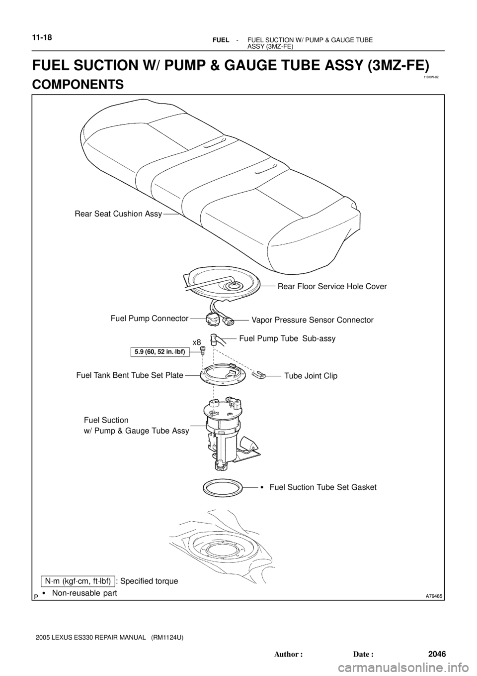
110XW-02
A79485 A79485� Non-reusable part
N´m (kgf´cm, ft´lbf) : Specified torque
5.9 (60, 52 in.Vlbf)
x8Fuel Pump Tube Sub-assy
Tube Joint Clip Fuel Tank Bent Tube Set Plate
Fuel Suction
w/ Pump & Gauge Tube Assy
� Fuel Suction Tube Set Gasket Vapor Pressure Sensor Connector Fuel Pump ConnectorRear Floor Service Hole Cover Rear Seat Cushion Assy
11-18- FUELFUEL SUCTION W/ PUMP & GAUGE TUBE
ASSY (3MZ-FE)
2046 Author�: Date�:
2005 LEXUS ES330 REPAIR MANUAL (RM1124U)
FUEL SUCTION W/ PUMP & GAUGE TUBE ASSY (3MZ-FE)
COMPONENTS
Page 604 of 969

2052 Author�: Date�:
2005 LEXUS ES330 REPAIR MANUAL (RM1124U)
24. INSTALL FUE")
A79489Mark
A81595
Tube Joint ClipCollar
A79487
New Butyl Tape
11-24- FUELFUEL SUCTION W/ PUMP & GAUGE TUBE
ASSY (3MZ-FE)
2052 Author�: Date�:
2005 LEXUS ES330 REPAIR MANUAL (RM1124U)
24. INSTALL FUEL SUCTION W/ PUMP & GAUGE TUBE
ASSY
(a) Install a new gasket to the fuel suction tube w/ pump &
gauge.
(b) Install the fuel suction tube w/ pump & gauge to the fuel
tank.
NOTICE:
�Do not damage the fuel pump filter.
�Do not bend the arm of the fuel sender gauge.
(c) Align the mark of the fuel tank vent tube set plate with the
fuel suction tube w/ pump & gauge.
(d) Install the fuel tank bent tube set plate with the 8 bolts.
Torque: 5.9 NVm (60 kgfVcm, 52 in.Vlbf)
(e) Install the fuel pump tube with the tube joint clip.
NOTICE:
�Check the connected part for scratch or foreign ob-
jects.
�Check that the fuel tube joint is inserted securely.
�Check that the tube joint clip is on the collar of the fuel
tube joint.
�After installing the tube joint clip, check that the fuel
tube joint has not been pulled off.
25. CONNECT ENGINE WIRE NO. 3 (BATTERY NEGATIVE TERMINAL)
Torque: 5.4 NVm (55 kgfVcm, 48 in.Vlbf)
26. CHECK FOR FUEL LEAKS (See page 11-5)
27. INSTALL REAR FLOOR SERVICE HOLE COVER
(a) Connect the fuel pump connector.
(b) Connect the vapor pressure sensor connector.
(c) Using new butyl tape, install the rear floor service hole
cover.
28. INSTALL REAR SEAT CUSHION ASSY
29. SYSTEM INITIALIZATION (See page 19-15)
Page 605 of 969
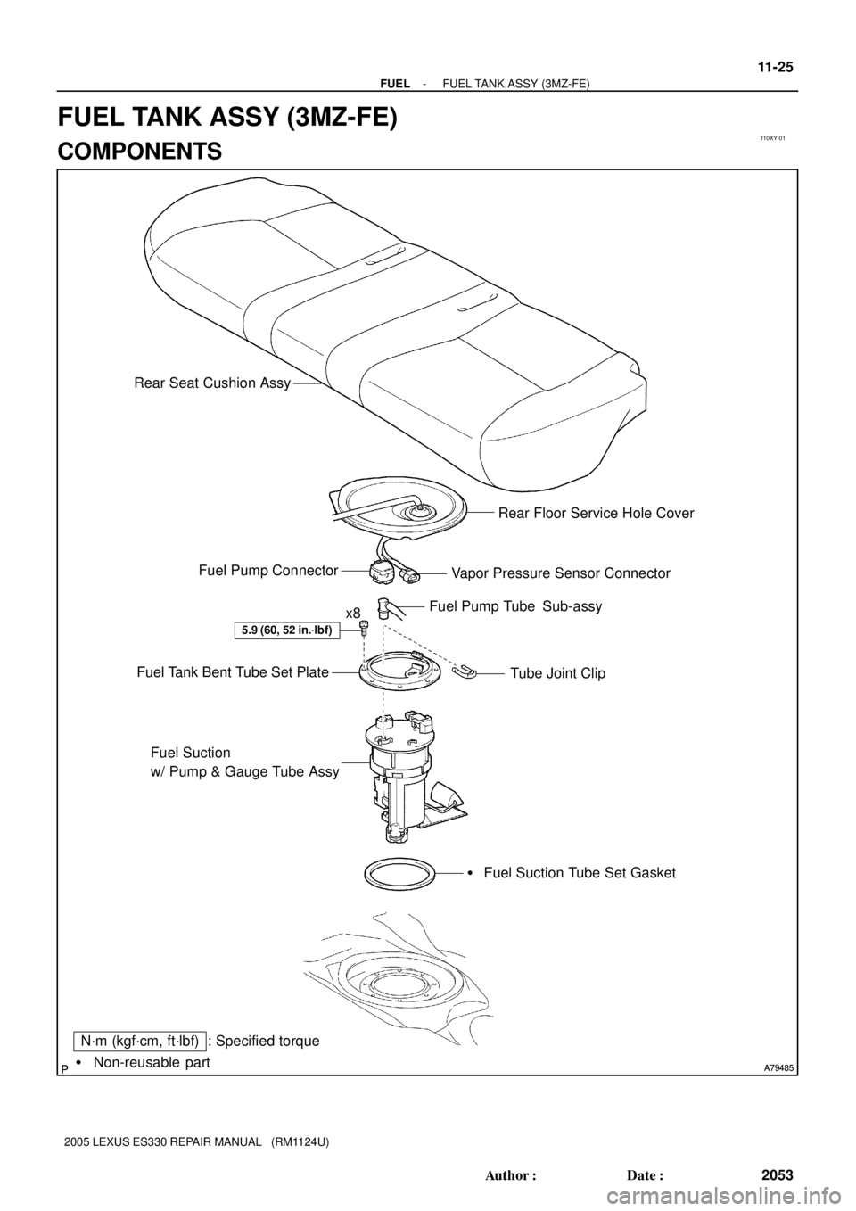
110XY-01
A79485 A79485� Non-reusable part
N´m (kgf´cm, ft´lbf) : Specified torque
5.9 (60, 52 in.Vlbf)
x8Fuel Pump Tube Sub-assy
Tube Joint Clip Fuel Tank Bent Tube Set Plate
Fuel Suction
w/ Pump & Gauge Tube Assy
� Fuel Suction Tube Set Gasket Vapor Pressure Sensor Connector Fuel Pump ConnectorRear Floor Service Hole Cover Rear Seat Cushion Assy
- FUELFUEL TANK ASSY (3MZ-FE)
11-25
2053 Author�: Date�:
2005 LEXUS ES330 REPAIR MANUAL (RM1124U)
FUEL TANK ASSY (3MZ-FE)
COMPONENTS
Page 606 of 969
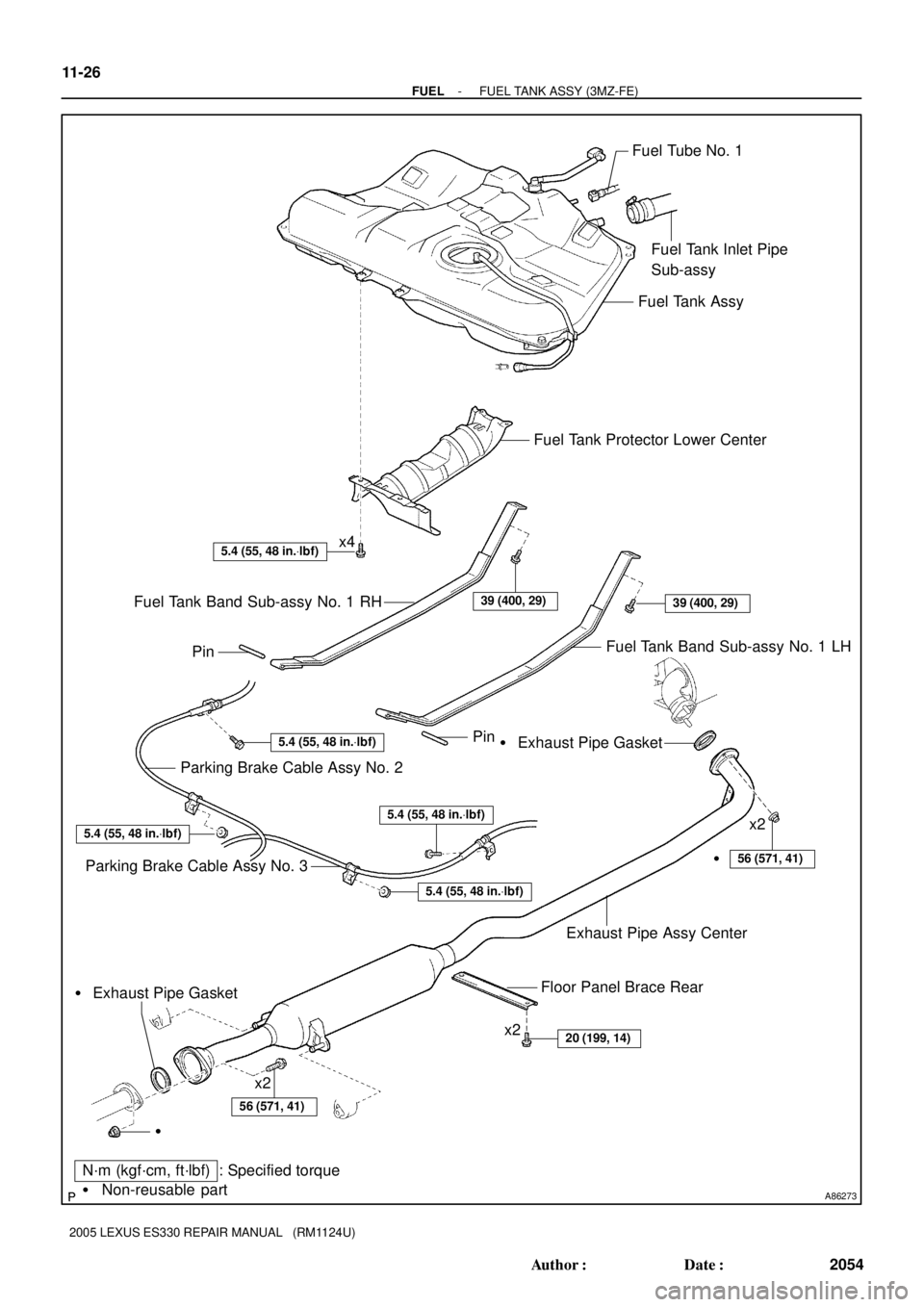
A86273� Non-reusable part
N´m (kgf´cm, ft´lbf) : Specified torque
20 (199, 14)
56 (571, 41)
5.4 (55, 48 in.Vlbf)
5.4 (55, 48 in.Vlbf)
5.4 (55, 48 in.Vlbf)
5.4 (55, 48 in.Vlbf)
5.4 (55, 48 in.Vlbf)
39 (400, 29)
Fuel Tube No. 1
Fuel Tank Inlet Pipe
Sub-assy
Fuel Tank Assy
Fuel Tank Protector Lower Center
Fuel Tank Band Sub-assy No. 1 LH Fuel Tank Band Sub-assy No. 1 RH
Parking Brake Cable Assy No. 2
Parking Brake Cable Assy No. 3� Exhaust Pipe Gasket Pin
x4
39 (400, 29)
Pin
Floor Panel Brace Rear
�
� Exhaust Pipe Gasket
56 (571, 41)
Exhaust Pipe Assy Center
�x2x2
x2
11-26
- FUELFUEL TANK ASSY (3MZ-FE)
2054 Author�: Date�:
2005 LEXUS ES330 REPAIR MANUAL (RM1124U)
 : Specified torque
7.9 (81, 70 in.Vlbf)x3
V-bank Cover Sub-assy
Mass Air Flow
Meter Connector Fuel Vapor Feed Hose
Assy
Vacuum Hose
Air Cleaner Cap
Sub-assy")