Page 41 of 969

(B)
I31544
(E)
(C)(D)
- HEATER & AIR CONDITIONERCOOLER COMPRESSOR ASSY
55-41
2656 Author�: Date�:
2005 LEXUS ES330 REPAIR MANUAL (RM1124U)
13. INSPECT COMPRESSOR OIL
(a) When repla")
I31546
I31561
(A)
(B)
I31544
(E)
(C)(D)
- HEATER & AIR CONDITIONERCOOLER COMPRESSOR ASSY
55-41
2656 Author�: Date�:
2005 LEXUS ES330 REPAIR MANUAL (RM1124U)
13. INSPECT COMPRESSOR OIL
(a) When replacing the compressor and magnetic clutch with new one, after gradually removing the refrig-
erant gas from the service valve, drain the following amount of oil from the new compressor and mag-
netic clutch before installation.
Standard:
(Oil capacity inside new compressor and magnetic clutch: 120 + 15 cc (4.1 + 0.51 fl.oz.) ) - (Re-
maining oil amount in the removed compressor and magnetic clutch) = (Oil amount to be re-
moved when replacing)
NOTICE:
�When checking the compressor oil level, observe the precautions on the cooler removal/instal-
lation.
�Because compressor oil remains in the pipes of the vehicle, if a new compressor and magnetic
clutch is installed without removing some oil inside, the oil amount becomes too much, pre-
venting heat exchange in the refrigerant cycle and causing refrigerant failure.
�If the remaining oil in the removed compressor and magnetic clutch is too small in volume,
check for oil leakage.
�Be sure to use ND-OIL8 for compressor oil.
14. TEMPORARY TIGHTEN COMPRESSOR AND
MAGNETIC CLUTCH
(a) Temporarily the compressor and magnetic clutch with the
3 bolts.
15. FULLY TIGHTEN COMPRESSOR AND MAGNETIC
CLUTCH
(a) Tighten the compressor and magnetic clutch with the bolt
(A) and bolt (B).
Torque: 25 NVm (250 kgfVcm, 18 ftVlbf)
(b) Install the cooler compressor bracket with the 2 bolts and
nut.
Torque:
25 NVm (250 kgfVcm, 18 ftVlbf) (Bolt (C))
25 NVm (250 kgfVcm, 18 ftVlbf) (Nut (D))
18 NVm (184 kgfVcm, 13 ftVlbf) (Bolt (E))
Page 200 of 969
4005R-08
D25120
Add if hotOK if hot
- AUTOMATIC TRANSMISSION / TRANSAUTOMATIC TRANSAXLE FLUID
40-1
2516 Author�: Date�:
2005 LEXUS ES330 REPAIR MANUAL (RM1124U)
AUTOMATIC TRANSAXLE FLUID
ON-VEHICLE INSPECTION
1. CHECK THE FLUID LEVEL
HINT:
Drive the vehicle so that the engine and transaxle are at normal
operating temperature.
Fluid temperature: 70 - 80 °C (158 - 176 °F)
(a) Park the vehicle on a level surface and set the parking
brake.
(b) With the engine idling and the brake pedal depressed,
shift the shift lever into all positions from P to L position,
and return to P position.
(c) take out the dipstick and wipe it clean.
(d) Put it back fully into the pipe.
(e) take it out and check that the fluid level is in the HOT posi-
tion.
If there are leaks, it is necessary to repair or replace O-rings,
FIPGs, oil seals, plugs and/or other parts.
Page 207 of 969

12 (122, 9)
64 (653, 47)
46 (470, 34)
Front Drive Shaft Assy RH
Transmission Control
Cable Bracket No.2
41 (418, 30)
12 (122, 9)
37 (377, 2")
4010Q-02
D31337
Bearing Bracket Hole Snap Ring
32 (326, 24)
12 (122, 9)
64 (653, 47)
46 (470, 34)
Front Drive Shaft Assy RH
Transmission Control
Cable Bracket No.2
41 (418, 30)
12 (122, 9)
37 (377, 27)
5.5 (56, 49 in.Vlbf)
9.8 (100, 87 in.Vlbf)
�
� Wire Harness
Automatic
Transmission Case
Cover
Front Drive
ShaftLH Hole
Snap Ring
Front Drive Shaft
Assy LH
Starter Assy
�O-ring
Transimission Oil
Filler Tube Sub-assy
ATF Level
Gauge Oil Cooler
Outlet Tube No.1 Oil Cooler Inlet
Tube No.1Oil Cooler Tube ClampTransmission Control
Cable Bracket No.1 Flywheel Housing
Under CoverTorque Converter ClutchEngine
Mounting
Bracket FR
X6
N´m (kgf´cm, ft´lbf): Specified torque
� Non-reusable partWire Harness Clamp
12 (122, 9)
12 (122, 9)
34 (350, 25)
8.4 (86, 74 in.Vlbf)
64 (653, 47)
5.4 (55, 48 in.Vlbf)
7.8 (80, 69 in.Vlbf)
13 (130, 9)
Exhaust Pipe Support Bracket
37 (377, 27)
34 (350, 25)
x 5 40-8
- AUTOMATIC TRANSMISSION / TRANSAUTOMATIC TRANSAXLE ASSY (U151E)
2523 Author�: Date�:
2005 LEXUS ES330 REPAIR MANUAL (RM1124U)
AUTOMATIC TRANSAXLE ASSY (U151E)
COMPONENTS
Page 209 of 969
D30864
Transmission
Wire Connector
Park/neutral Position Switch Connector
Transmission Revolution
Sensor Connectors
C91736
C91737
C88047
SST
40-10
- AUTOMATIC TRANSMISSION / TRANSAUTOMATIC TRANSAXLE ASSY (U151E)
2525 Author�: Date�:
2005 LEXUS ES330 REPAIR MANUAL (RM1124U)
8. DISCONNECT CONNECTORS
(a) Disconnect the transmission wire connector.
(b) Disconnect the park/neutral position switch connector.
(c) Disconnect the 2 transmission revolution sensor connec-
tors.
9. REMOVE TRANSMISSION CONTROL CABLE
BRACKET NO.1
(a) Remove the bolt and oil cooler tube clamp.
(b) Remove the 2 bolts and transmission control cable brack-
et.
10. REMOVE TRANSMISSION OIL FILLER TUBE
SUB-ASSY
(a) Remove the ATF level gauge.
(b) Remove the bolt and oil filler tube.
(c) Remove the O-ring from the oil filler tube.
11. REMOVE OIL COOLER INLET TUBE NO.1
(a) Using SST and spanner, disconnect the oil cooler inlet
tube No.1.
SST 09023-12701
Page 213 of 969

2529 Author�: Date�:
2005 LEXUS ES330 REPAIR MANUAL (RM1124U)
(d) Install the")
D31340
D25420
C88135
D31339
Breather Hose
C88278
40-14
- AUTOMATIC TRANSMISSION / TRANSAUTOMATIC TRANSAXLE ASSY (U151E)
2529 Author�: Date�:
2005 LEXUS ES330 REPAIR MANUAL (RM1124U)
(d) Install the flywheel housing under cover with the 2 bolts.
Torque: 7.8 NVm (80 kgfVcm, 69 in.Vlbf)
21. INSTALL ENGINE MOUNTING BRACKET FR
(a) Install the engine mounting bracket FR with the 3 bolts to
the automatic transaxle.
Torque: 64 NVm (653 kgfVcm, 47 ftVlbf)
22. INSTALL TRANSMISSION OIL FILLER TUBE
SUB-ASSY
(a) Coat a new O-ring with ATF, and install it to the oil filler
tube.
(b) Install the oil filler tube with the bolt to the automatic trans-
axle.
Torque: 5.5 NVm (56 kgfVcm, 49 in.Vlbf)
(c) Install the ATF level gauge.
(d) Connect the breather hose to the wire harness bracket.
23. INSTALL TRANSMISSION CONTROL CABLE
BRACKET NO.1
(a) Install the control cable bracket No.1 with the 2 bolts.
Torque: 12 NVm (122 kgfVcm, 9 ftVlbf)
24. INSTALL OIL COOLER INLET TUBE NO.1
(a) Temporarily install the oil cooler outlet tube No.1.
(b) Temporarily install the oil cooler inlet tube No.1.
Page 284 of 969

(2) Install the wear indicator to the 2 brake pads.
NOTICE:
�When replac")
F41866
Anti Squeal
Shim
Wear Indicator
- BRAKEFRONT BRAKE
32-39
2473 Author�: Date�:
2005 LEXUS ES330 REPAIR MANUAL (RM1124U)
(2) Install the wear indicator to the 2 brake pads.
NOTICE:
�When replacing worn pads, the anti squeal shims
must be replaced together with the pads.
�Install the shims and pad wear indicator correctly of
which positions and directions.
(b) Install the anti squeal shim kit front (Twin piston Type).
(1) Apply the anti squeal shim with pad grease, and
install the anti squeal shim to each pad.
(2) Install the wear indicator to the 2 brake pads.
NOTICE:
�When replacing worn pads, the anti squeal shims
must be replaced together with the pads.
�Install the shims and pad wear indicator correctly of
which positions and directions.
38. INSTALL DISC BRAKE PAD KIT FRONT (PAD ONLY)
(a) Install the 2 disc brake pads with the pad wear indicator facing upward.
NOTICE:
There should be no oil or grease on the friction surface of the pads and the disc.
39. INSTALL DISC BRAKE CYLINDER ASSY LH
(a) Install the disc brake cylinder with the 2 bolts.
Torque: 34.3 NVm (350 kgfVcm, 25 ftVlbf)
40. CONNECT FRONT FLEXIBLE HOSE
(a) Connect a new gasket and flexible hose with the union bolt.
Torque: 29.4 NVm (300 kgfVcm, 22 ftVlbf)
HINT:
Install the flexible hose lock securely in the lock hold of the disc brake cylinder.
41. FILL RESERVOIR WITH BRAKE FLUID
42. BLEED MASTER CYLINDER (SEE PAGE 32-4)
SST 09023-00101
43. BLEED BRAKE LINE (SEE PAGE 32-4)
44. CHECK FLUID LEVEL IN RESERVOIR (SEE PAGE 32-4)
45. CHECK BRAKE FLUID LEAKAGE
46. INSTALL FRONT WHEEL
Torque: 103 NVm (1,050 kgfVcm, 76 ftVlbf)
Page 361 of 969

2419 Author�: Date�:
2005 LEXUS ES330 REPAIR MANUAL (RM1124U)
(b) Claw Engagement type
(1) Using")
F07391
C91598
R00764
C83851
30-16
- DRIVE SHAFT / PROPELLER SHAFTFRONT DRIVE SHAFT (From July, 2003)
2419 Author�: Date�:
2005 LEXUS ES330 REPAIR MANUAL (RM1124U)
(b) Claw Engagement type
(1) Using pliers, install the front axle inboard joint boot
LH clamp and front axle inboard joint boot LH No.2
clamp, as shown in the illustration.
35. INSPECT FRONT DRIVE SHAFT
NOTICE:
Move the drive shaft assy keeping it level.
(a) Check that there is no remarkable play in the radial direc-
tion of the outboard joint.
(b) Check that the inboard joint slides smoothly in the thrust
direction.
(c) Check that there is no remarkable play in the radial direc-
tion of the inboard joint.
(d) Check the boots for damage.
(e) Make sure that the 2 boots are on the shaft groove.
(f) Make sure that the 2 boots are not stretched or contracted
when the drive shaft is at standard length.
Drive shaft standard length: mm (in.)
LH576.9 � 2.0 (22.713 � 0.079)
RH896.4 � 2.0 (35.291 � 0.079)
36. INSTALL FRONT DRIVE SHAFT ASSY LH
(a) Install a new front drive shaft LH hole snap ring.
(b) Coat the spline of the inboard joint shaft assy with ATF.
(c) Align the shaft splines and install the drive shaft assy with
a brass bar and hammer.
NOTICE:
�Set the snap ring with the opening side facing down-
ward.
�Be careful not to damage the oil seal, boot and dust
cover.
�Move the drive shaft assy while keeping it level.
Page 399 of 969
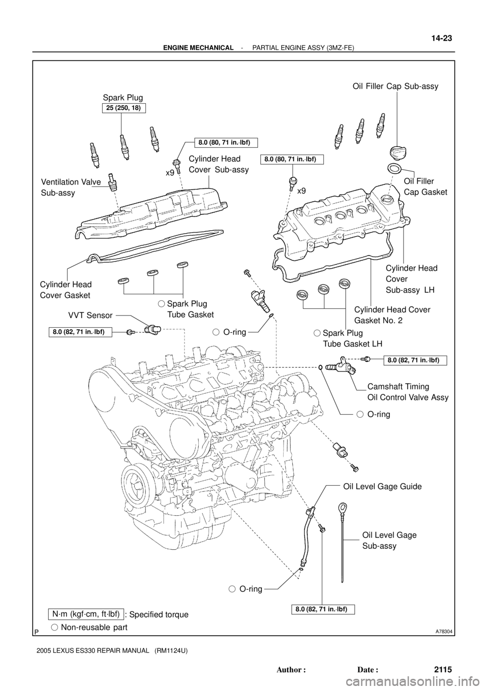
A78304
N´m (kgf´cm, ft´lbf)
: Specified torque
� Non-reusable part� O-ring� O-ring8.0 (82, 71 in.Vlbf)
8.0 (82, 71 in.Vlbf)
8.0 (82, 71 in.Vlbf)
8.0 (80, 71 in.Vlbf)
8.0 (80, 71 in.Vlbf)
25 (250, 18)
Spark Plug
Ventilation Valve
Sub-assyCylinder Head
Cover Sub-assy
Cylinder Head
Cover Gasket
VVT Sensor� Spark Plug
Tube Gasket
� O-ringOil Filler Cap Sub-assy
Oil Filler
Cap Gasket
Cylinder Head
Cover
Sub-assy LH
Cylinder Head Cover
Gasket No. 2
� Spark Plug
Tube Gasket LH
Camshaft Timing
Oil Control Valve Assy
Oil Level Gage Guide
Oil Level Gage
Sub-assy
x9
x9
- ENGINE MECHANICALPARTIAL ENGINE ASSY (3MZ-FE)
14-23
2115 Author�: Date�:
2005 LEXUS ES330 REPAIR MANUAL (RM1124U)