Page 10 of 969

550D7-02
I30370
Bolt C
Bolt ABolt B
I30370
I30370
Measuring
Position
Bolt B
N01881
DENSO Boroughs 55-10
- HEATER & AIR CONDITIONERV (COOLER COMPRESSOR TO CRANKSHAFT
PULLEY) BELT NO.1
2625 Author�: Date�:
2005 LEXUS ES330 REPAIR MANUAL (RM1124U)
V (COOLER COMPRESSOR TO CRANKSHAFT PULLEY)
BELT NO.1
REPLACEMENT
1. REMOVE V (COOLER COMPRESSOR TO
CRANKSHAFT PULLEY) BELT NO.1
(a) Loosen the bolt C.
(b) Loosen the bolt A.
(c) Loosen the bolt B and remove the cooler V belt No. 1.
2. INSTALL V (COOLER COMPRESSOR TO
CRANKSHAFT PULLEY) BELT NO.1
(a) Temporarily install the cooler V belt No. 1 as illustrated.
3. ADJUST V (COOLER COMPRESSOR TO
CRANKSHAFT PULLEY) BELT NO.1
(a) Apply drive belt tension by turning the bolt B.
Drive belt tension:
New Belt: 165 � 27 lbf
Used belt: 88 � 22 lbf
HINT:
�ºNew beltº refers to a belt which has been used less than
5 minutes on a running engine.
�ºUsed beltº refers to a belt which has been used on a run-
ning engine for 5 minutes or more.
�After installing the drive belt, check that it fits properly in
the ribbed grooves.
Page 11 of 969
CH0086
Wrong Correct
I30370
Bolt C
Bolt A
- HEATER & AIR CONDITIONERV (COOLER COMPRESSOR TO CRANKSHAFT
PULLEY) BELT NO.155-1 1
2626 Author�: Date�:
2005 LEXUS ES330 REPAIR MANUAL (RM1124U)
�Check that the drive belt fits properly in the ribbed
grooves.
4. FULLY TIGHTEN V (COOLER COMPRESSOR TO
CRANKSHAFT PULLEY) BELT NO.1
(a) Tighten the bolt A.
Torque: 17.5 NVm (178 kgfVcm, 12 ftVlbf)
(b) Tighten the bolt C.
Torque: 58 NVm (591 kgfVcm, 43 ftVlbf)
Page 37 of 969

550DF-02
I31543
I31542
I31544
- HEATER & AIR CONDITIONERCOOLER COMPRESSOR ASSY
55-37
2652 Author�: Date�:
2005 LEXUS ES330 REPAIR MANUAL (RM1124U)
REPLACEMENT
HINT:
COMPONENTS: See page 55-36
1. DISCHARGE REFRIGERANT FROM REFRIGERATION SYSTEM (See page 55-8)
SST 07110-58060 (07117-58080, 07117-58090, 07117-78050, 07117-88060, 07117-88070,
07117-88080)
2. REMOVE V (COOLER COMPRESSOR TO CRANKSHAFT PULLEY) BELT NO.1
(See page 55-10)
3. REMOVE GENERATOR ASSY (See page 19-21)
4. DISCONNECT COOLER REFRIGERANT DISCHARGE
HOSE NO.1
(a) Remove the nut and disconnect the cooler refrigerant dis-
charge hose No. 1.
(b) Remove the O-ring from the cooler refrigerant discharge
hose No. 1.
NOTICE:
Seal the opening of the disconnected parts using vinyl tape
to prevent moisture and foreign matter from entering.
5. DISCONNECT COOLER REFRIGERANT SUCTION
HOSE NO.1
(a) Remove the nut and disconnect the cooler refrigerant
suction hose No. 1.
(b) Remove the O-ring from the cooler refrigerant suction
hose No. 1.
NOTICE:
Seal the opening of the disconnected parts using vinyl tape
to prevent moisture and foreign matter from entering.
6. REMOVE COMPRESSOR AND MAGNETIC CLUTCH
(a) Disconnect the connector and clamp.
(b) Remove the 2 bolts, nut and cooler compressor bracket.
Page 42 of 969

I31562
(F)
I31542
I31543
55-42
- HEATER & AIR CONDITIONERCOOLER COMPRESSOR ASSY
2657 Author�: Date�:
2005 LEXUS ES330 REPAIR MANUAL (RM1124U)
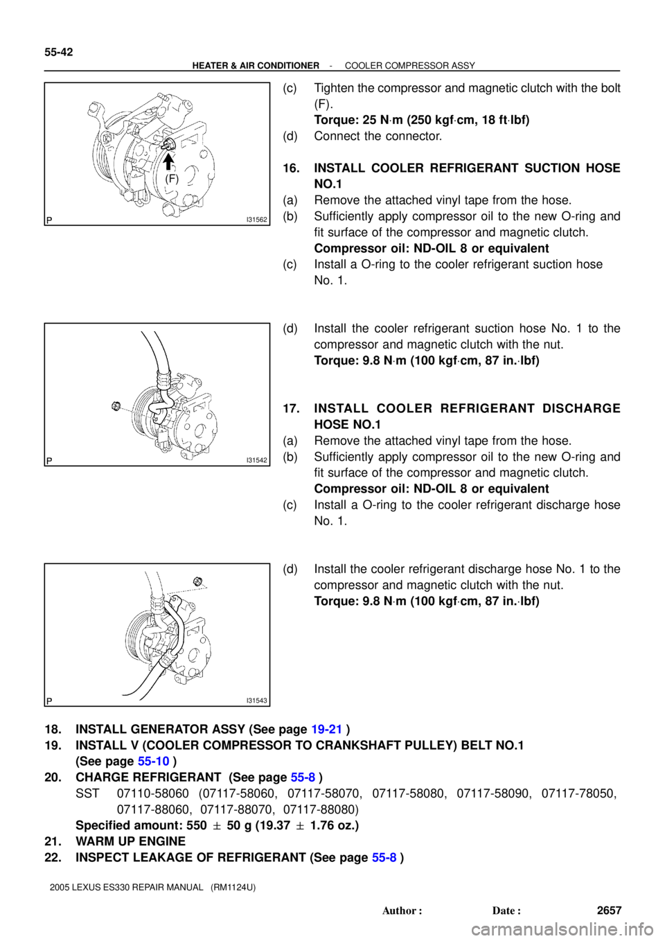
(c) Tighten the compressor and magnetic clutch with the bolt
(F).
Torque: 25 NVm (250 kgfVcm, 18 ftVlbf)
(d) Connect the connector.
16. INSTALL COOLER REFRIGERANT SUCTION HOSE
NO.1
(a) Remove the attached vinyl tape from the hose.
(b) Sufficiently apply compressor oil to the new O-ring and
fit surface of the compressor and magnetic clutch.
Compressor oil: ND-OIL 8 or equivalent
(c) Install a O-ring to the cooler refrigerant suction hose
No. 1.
(d) Install the cooler refrigerant suction hose No. 1 to the
compressor and magnetic clutch with the nut.
Torque: 9.8 NVm (100 kgfVcm, 87 in.Vlbf)
17. INSTALL COOLER REFRIGERANT DISCHARGE
HOSE NO.1
(a) Remove the attached vinyl tape from the hose.
(b) Sufficiently apply compressor oil to the new O-ring and
fit surface of the compressor and magnetic clutch.
Compressor oil: ND-OIL 8 or equivalent
(c) Install a O-ring to the cooler refrigerant discharge hose
No. 1.
(d) Install the cooler refrigerant discharge hose No. 1 to the
compressor and magnetic clutch with the nut.
Torque: 9.8 NVm (100 kgfVcm, 87 in.Vlbf)
18. INSTALL GENERATOR ASSY (See page 19-21)
19. INSTALL V (COOLER COMPRESSOR TO CRANKSHAFT PULLEY) BELT NO.1
(See page 55-10)
20. CHARGE REFRIGERANT (See page 55-8)
SST 07110-58060 (07117-58060, 07117-58070, 07117-58080, 07117-58090, 07117-78050,
07117-88060, 07117-88070, 07117-88080)
Specified amount: 550 � 50 g (19.37 � 1.76 oz.)
21. WARM UP ENGINE
22. INSPECT LEAKAGE OF REFRIGERANT (See page 55-8)
Page 377 of 969

141C0-02
A82940
Vane Pump
CrankshaftGenerator Measuring Points for Belt Deflection
or Tension
Compressor
- ENGINE MECHANICALENGINE (3MZ-FE)
14-1
2093 Author�: Date�:
2005 LEXUS ES330 REPAIR MANUAL (RM1124U)
ENGINE (3MZ-FE)
INSPECTION
1. INSPECT ENGINE COOLANT (See page 16-1)
2. INSPECT ENGINE OIL
3. INSPECT BATTERY
Standard specific gravity: 1.25 to 1.29 at 20�C (68�F)
4. INSPECT AIR CLEANER FILTER ELEMENT SUB-ASSY
5. INSPECT SPARK PLUG (See page 18-3)
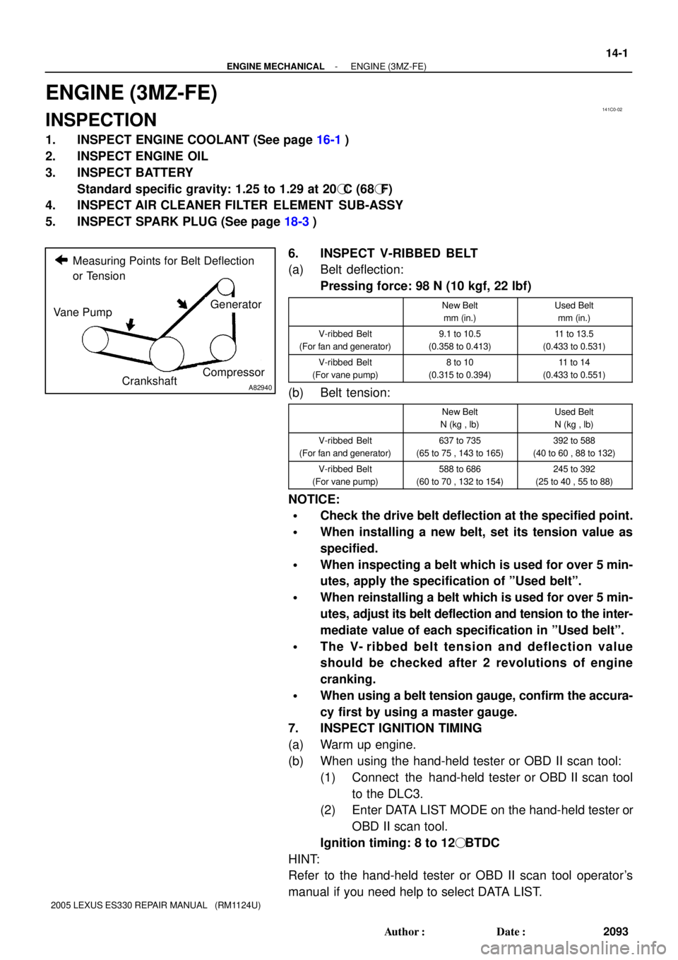
6. INSPECT V-RIBBED BELT
(a) Belt deflection:
Pressing force: 98 N (10 kgf, 22 lbf)
New Belt
mm (in.)Used Belt
mm (in.)
V-ribbed Belt
(For fan and generator)9.1 to 10.5
(0.358 to 0.413)11 to 13.5
(0.433 to 0.531)
V-ribbed Belt
(For vane pump)8 to 10
(0.315 to 0.394)11 to 14
(0.433 to 0.551)
(b) Belt tension:
New Belt
N (kg , lb)Used Belt
N (kg , lb)
V-ribbed Belt
(For fan and generator)637 to 735
(65 to 75 , 143 to 165)392 to 588
(40 to 60 , 88 to 132)
V-ribbed Belt
(For vane pump)588 to 686
(60 to 70 , 132 to 154)245 to 392
(25 to 40 , 55 to 88)
NOTICE:
�Check the drive belt deflection at the specified point.
�When installing a new belt, set its tension value as
specified.
�When inspecting a belt which is used for over 5 min-
utes, apply the specification of ºUsed beltº.
�When reinstalling a belt which is used for over 5 min-
utes, adjust its belt deflection and tension to the inter-
mediate value of each specification in ºUsed beltº.
�The V- ribbed belt tension and deflection value
should be checked after 2 revolutions of engine
cranking.
�When using a belt tension gauge, confirm the accura-
cy first by using a master gauge.
7. INSPECT IGNITION TIMING
(a) Warm up engine.
(b) When using the hand-held tester or OBD II scan tool:
(1) Connect the hand-held tester or OBD II scan tool
to the DLC3.
(2) Enter DATA LIST MODE on the hand-held tester or
OBD II scan tool.
Ignition timing: 8 to 12� BTDC
HINT:
Refer to the hand-held tester or OBD II scan tool operator's
manual if you need help to select DATA LIST.
Page 381 of 969

14193-03
A78698
B
AC
A78699
A
B
A78699
A
B
A78698
B
AC
- ENGINE MECHANICALDRIVE BELT (3MZ-FE)
14-5
2097 Author�: Date�:
2005 LEXUS ES330 REPAIR MANUAL (RM1124U)
DRIVE BELT (3MZ-FE)
REPLACEMENT
1. REMOVE FRONT WHEEL RH
2. REMOVE FRONT FENDER APRON SEAL RH
3. REMOVE V (COOLER COMPRESSOR TO
CRANKSHAFT PULLEY) BELT NO.1
(a) Loosen bolts A and B.
(b) Loosen the adjusting bolt C, then remove the V-ribbed
belt.
4. REMOVE VANE PUMP V BELT
(a) Loosen bolts A and B, then remove the V-ribbed belt.
5. INSTALL VANE PUMP V BELT
(a) Install the V-ribbed belt on each pulley.
(b) Using a bar, adjust the V-ribbed belt tension, then tighten
bolt B.
Torque: 43 NVm (439 kgfVcm, 32 ftVlbf)
(c) Tighten bolt A.
Torque: 43 NVm (439 kgfVcm, 32 ftVlbf)
6. INSTALL V (COOLER COMPRESSOR TO
CRANKSHAFT PULLEY) BELT NO.1
(a) Install the V-ribbed belt on each pulley.
(b) Tighten the adjusting bolt C, then adjust the V-ribbed belt
tension.
(c) First tighten bolt A, then tighten bolt B.
Torque:
18 NVm (178 kgfVcm, 13 ftVlbf) for bolt A
58 NVm (591 kgfVcm, 43 ftVlbf) for bolt B
Page 382 of 969
14-6
- ENGINE MECHANICALDRIVE BELT (3MZ-FE)
2098 Author�: Date�:
2005 LEXUS ES330 REPAIR MANUAL (RM1124U)
7. INSPECT DRIVE BELT DEFLECTION AND TENSION (See page 14-1)
8. INSTALL FRONT WHEEL RH
Torque: 103 NVm (1,050 kgfVcm, 76 ftVlbf)
Page 383 of 969

141J7-02
A78541
(b)
(b)
(b)(a)
(a)
A36719
P18805
- ENGINE MECHANICALVALVE CLEARANCE (3MZ-FE)
14-7
2099 Author�: Date�:
2005 LEXUS ES330 REPAIR MANUAL (RM1124U)
VALVE CLEARANCE (3MZ-FE)
ADJUSTMENT
1. DISCONNECT BATTERY NEGATIVE TERMINAL
2. DRAIN ENGINE COOLANT (See page 16-9)
3. REMOVE FRONT FENDER APRON SEAL RH
4. REMOVE FRONT SUSPENSION UPPER BRACE CENTER (W/O TEMS) (See page 10-1 1)
5. REMOVE V-BANK COVER SUB-ASSY (See page 10-1 1)
6. REMOVE AIR CLEANER CAP SUB-ASSY (See page 10-1 1)
7. REMOVE EMISSION CONTROL VALVE SET (See page 11-13)
8. REMOVE INTAKE AIR SURGE TANK (See page 11-13)
9. REMOVE RADIATOR HOSE INLET
10. REMOVE IGNITION COIL ASSY
11. REMOVE CYLINDER HEAD COVER SUB-ASSY
(a) Remove the 2 engine wire harness clamps.
(b) Remove the 3 nuts, then disconnect the engine wire har-
ness.
(c) Remove the 9 bolts and cylinder head cover.
12. REMOVE CYLINDER HEAD COVER SUB-ASSY LH
(a) Using an E6 Torx) socket wrench, remove the 2 bolts and
disconnect the engine wire harness protector.
(b) Remove the 9 bolts and cylinder head cover.
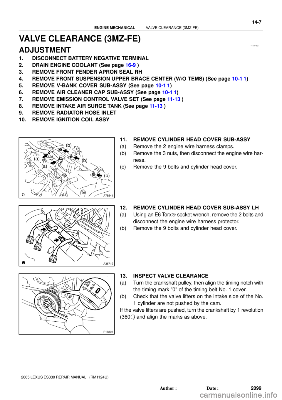
13. INSPECT VALVE CLEARANCE
(a) Turn the crankshaft pulley, then align the timing notch with
the timing mark º0º of the timing belt No. 1 cover.
(b) Check that the valve lifters on the intake side of the No.
1 cylinder are not pushed by the cam.
If the valve lifters are pushed, turn the crankshaft by 1 revolution
(360�) and align the marks as above.