2004 SUBARU FORESTER coolant temperature
[x] Cancel search: coolant temperaturePage 1328 of 2870

EN(H4SO)-230
ENGINE (DIAGNOSTIC)
Diagnostic Procedure with Diagnostic Trouble Code (DTC)
Step Check Yes No
1 CHECK ANY OTHER DTC ON DISPLAY.Is any other DTC displayed? Inspect the DTC
using “List of Diag-
nostic Trouble
Code (DTC)”.
of Diagnostic Trou-
ble Code (DTC).>Go to step 2.
2 CHECK FRONT (A/F) OXYGEN SENSOR DA-
TA.
1) Start the engine.
2) While observing the Subaru Select Monitor
or OBD-II general scan tool screen, warm-up
the engine until coolant temperature is above
70°C (160°F).
If the engine is already warmed-up, operate at
idle speed for at least 1 minute.
3) Read the data of front oxygen (A/F) sensor
signal at idling using Subaru Select Monitor or
OBD-II general scan tool.
NOTE:
Subaru Select Monitor
For detailed operation procedure, refer to the
“READ CURRENT DATA FOR ENGINE”.
OBD-II general scan tool
For detailed operation procedures, refer to the
OBD-II General Scan Tool Operation Manual.Is the voltage 0.85 — 1.15 V? Go to step 3.Go to step 4.
3 CHECK FRONT (A/F) OXYGEN SENSOR DA-
TA.
Race the engine at speeds from idling to 5,000
rpm for a total of 5 cycles.
N
OTE:
Normally the air fuel ratio be rich at racing.
To increase engine speed to 5,000 rpm,
slowly depress accelerator pedal, taking
approximately 5 seconds, and quickly release
accelerator pedal to decrease engine speed.Is the voltage more than 1.1 V? Go to step 6.Go to step 4.
4 CHECK HARNESS BETWEEN ECM AND
FRONT OXYGEN (A/F) SENSOR.
1) Turn the ignition switch to OFF.
2) Disconnect the connector from ECM and
front oxygen (A/F) sensor connector.
3) Measure the resistance between ECM and
front oxygen (A/F) sensor.
Connector & terminal
(B136) No. 13 — (B18) No. 1:
(B136) No. 22 — (B18) No. 2:Is the resistance less than 5
Ω?Go to step 5.Repair open circuit
between ECM and
front oxygen (A/F)
sensor.
5 CHECK HARNESS BETWEEN ECM AND
FRONT OXYGEN (A/F) SENSOR.
Measure the resistance between ECM and
chassis ground.
Connector & terminal
(B136) No. 13 — Chassis ground:
(B136) No. 22 — Chassis ground:Is the resistance more than 1
MΩ?Go to step 6.Repair ground
short circuit
between ECM and
front oxygen (A/F)
sensor.
Page 1353 of 2870

EN(H4SO)-255
ENGINE (DIAGNOSTIC)
General Diagnostic Table
20.General Diagnostic Table
A: INSPECTION
1. ENGINE
NOTE:
Malfunction of parts other than those listed is also possible.
Symptom Problem parts
1. Engine stalls during idling.1) Idle air control solenoid valve
2) Manifold absolute pressure sensor
3) Intake air temperature sensor
4) Ignition parts (*1)
5) Engine coolant temperature sensor (*2)
6) Crankshaft position sensor (*3)
7) Camshaft position sensor (*3)
8) Fuel injection parts (*4)
2. Rough idling1) Idle air control solenoid valve
2) Manifold absolute pressure sensor
3) Intake air temperature sensor
4) Engine coolant temperature sensor (*2)
5) Ignition parts (*1)
6) Air intake system (*5)
7) Fuel injection parts (*4)
8) Throttle position sensor
9) Crankshaft position sensor (*3)
10) Camshaft position sensor (*3)
11) Oxygen sensor
12) Fuel pump and fuel pump relay
3. Engine does not return to idle.1) Idle air control solenoid valve
2) Engine coolant temperature sensor
3) Accelerator cable (*6)
4) Throttle position sensor
5) Manifold absolute pressure sensor
6) Intake air temperature sensor
4. Poor acceleration1) Manifold absolute pressure sensor
2) Intake air temperature sensor
3) Throttle position sensor
4) Fuel injection parts (*4)
5) Fuel pump and fuel pump relay
6) Engine coolant temperature sensor (*2)
7) Crankshaft position sensor (*3)
8) Camshaft position sensor (*3)
9) A/C switch and A/C cut relay
10) Engine torque control signal circuit
11) Ignition parts (*1)
5. Engine stalls or engine sags or hesitates at
acceleration.1) Manifold absolute pressure sensor
2) Intake air temperature sensor
3) Engine coolant temperature sensor (*2)
4) Crankshaft position sensor (*3)
5) Camshaft position sensor (*3)
6) Purge control solenoid valve
7) Fuel injection parts (*4)
8) Throttle position sensor
9) Fuel pump and fuel pump relay
Page 1354 of 2870

EN(H4SO)-256
ENGINE (DIAGNOSTIC)
General Diagnostic Table
*1: Check ignition coil & ignitor ASSY and spark plug.
*2: Indicate the symptom occurring only in cold temperatures.
*3: Ensure the secure installation.
*4: Check fuel injector, fuel pressure regulator and fuel filter.
*5: Inspect air leak in air intake system.
*6: Adjust the accelerator cable.
2. AUTOMATIC TRANSMISSION
NOTE:
Check general diagnostics table with non-conformity symptom for automatic transmission.
6. Surging1) Intake manifold pressure sensor
2) Intake air temperature sensor
3) Manifold absolute pressure sensor
4) Engine coolant temperature sensor (*2)
5) Crankshaft position sensor (*3)
6) Camshaft position sensor (*3)
7) Fuel injection parts (*4)
8) Throttle position sensor
9) Fuel pump and fuel pump relay
7. Spark knock1) Intake manifold pressure sensor
2) Intake air temperature sensor
3) Manifold absolute pressure sensor
4) Engine coolant temperature sensor
5) Knock sensor
6) Fuel injection parts (*4)
7) Fuel pump and fuel pump relay
8. After burning in exhaust system1) Intake manifold pressure sensor
2) Intake air temperature sensor
3) Manifold absolute pressure sensor
4) Engine coolant temperature sensor (*2)
5) Fuel injection parts (*4)
6) Fuel pump and fuel pump relay Symptom Problem parts
Page 1356 of 2870

FUEL INJECTION (FUEL SYSTEM)
FU(H4DOTC)
Page
1. General Description ....................................................................................2
2. Throttle Body .............................................................................................13
3. Intake Manifold ..........................................................................................14
4. Engine Coolant Temperature Sensor........................................................29
5. Crankshaft Position Sensor.......................................................................30
6. Camshaft Position Sensor.........................................................................31
7. AVCS Camshaft Position Sensor ..............................................................32
8. Knock Sensor ............................................................................................33
9. Throttle Position Sensor ............................................................................34
10. Mass Air Flow and Intake Air Temperature Sensor ..................................35
11. Manifold Absolute Pressure Sensor ..........................................................36
12. Idle Air Control Solenoid Valve .................................................................37
13. Fuel Injector ..............................................................................................38
14. Tumble Generator Valve Assembly ..........................................................42
15. Tumble Generator Valve Actuator.............................................................43
16. Wastegate Control Solenoid Valve Assembly ...........................................44
17. Front Oxygen (A/F) Sensor .......................................................................45
18. Rear Oxygen Sensor.................................................................................47
19. Exhaust Temperature Sensor ...................................................................49
20. Engine Control Module (ECM) ..................................................................50
21. Main Relay ................................................................................................51
22. Fuel Pump Relay.......................................................................................52
23. Fuel Pump Control Unit .............................................................................53
24. Fuel ...........................................................................................................54
25. Fuel Tank ..................................................................................................55
26. Fuel Filler Pipe ..........................................................................................58
27. Fuel Pump .................................................................................................62
28. Fuel Level Sensor .....................................................................................64
29. Fuel Sub Level Sensor ..............................................................................65
30. Fuel Filter ..................................................................................................67
31. Fuel Cut Valve...........................................................................................68
32. Fuel Damper Valve ...................................................................................69
33. Fuel Delivery, Return and Evaporation Lines............................................70
34. Fuel System Trouble in General ...............................................................73
Page 1370 of 2870

FU(H4DOTC)-15
FUEL INJECTION (FUEL SYSTEM)
Intake Manifold
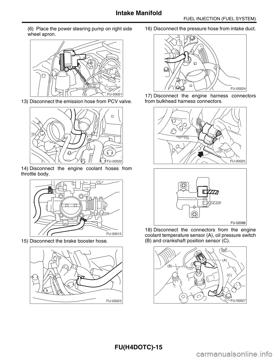
(6) Place the power steering pump on right side
wheel apron.
13) Disconnect the emission hose from PCV valve.
14) Disconnect the engine coolant hoses from
throttle body.
15) Disconnect the brake booster hose.16) Disconnect the pressure hose from intake duct.
17) Disconnect the engine harness connectors
from bulkhead harness connectors.
18) Disconnect the connectors from the engine
coolant temperature sensor (A), oil pressure switch
(B) and crankshaft position sensor (C).
FU-00021
FU-00022
FU-00012
FU-00023
FU-00024
FU-00025
FU-02086
(A)
(B)
(C)
FU-00027
Page 1373 of 2870

FU(H4DOTC)-18
FUEL INJECTION (FUEL SYSTEM)
Intake Manifold
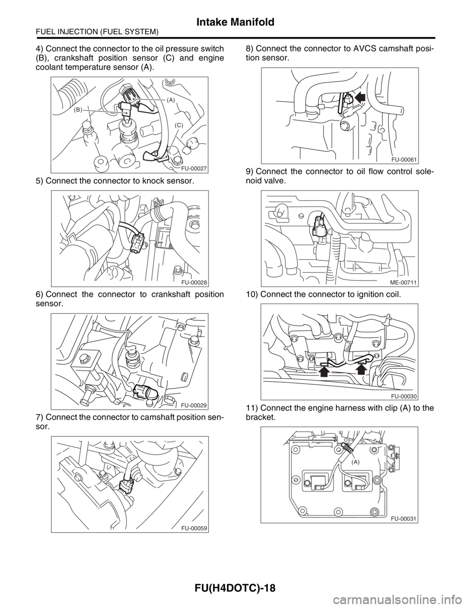
4) Connect the connector to the oil pressure switch
(B), crankshaft position sensor (C) and engine
coolant temperature sensor (A).
5) Connect the connector to knock sensor.
6) Connect the connector to crankshaft position
sensor.
7) Connect the connector to camshaft position sen-
sor.8) Connect the connector to AVCS camshaft posi-
tion sensor.
9) Connect the connector to oil flow control sole-
noid valve.
10) Connect the connector to ignition coil.
11) Connect the engine harness with clip (A) to the
bracket.
(A)
(B)
(C)
FU-00027
FU-00028
FU-00029
FU-00059
FU-00061
ME-00711
FU-00030
FU-00031
(A)
Page 1384 of 2870

FU(H4DOTC)-29
FUEL INJECTION (FUEL SYSTEM)
Engine Coolant Temperature Sensor
4. Engine Coolant Temperature
Sensor
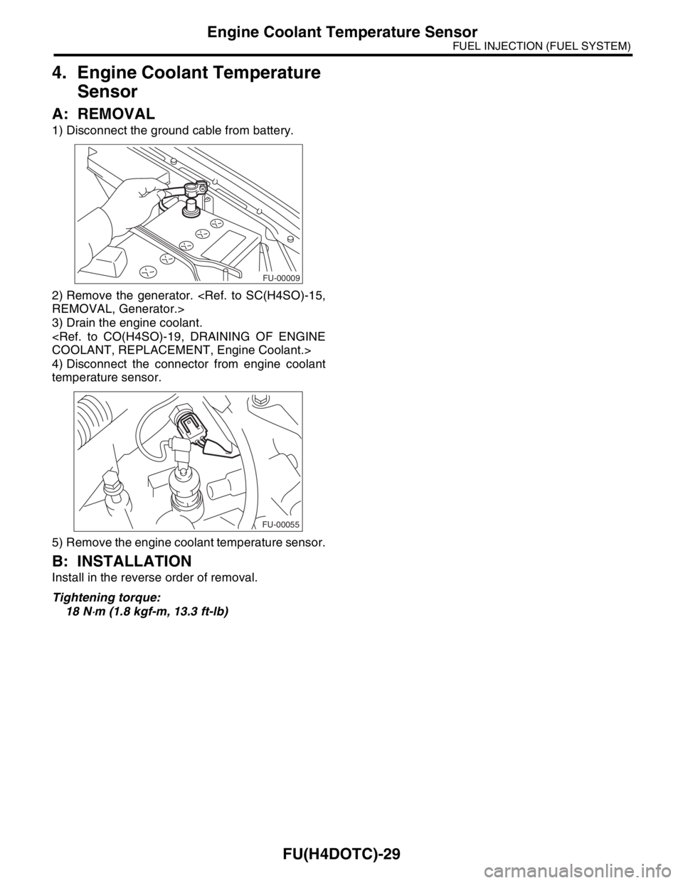
A: REMOVAL
1) Disconnect the ground cable from battery.
2) Remove the generator.
3) Drain the engine coolant.
4) Disconnect the connector from engine coolant
temperature sensor.
5) Remove the engine coolant temperature sensor.
B: INSTALLATION
Install in the reverse order of removal.
Tightening torque:
18 N
⋅m (1.8 kgf-m, 13.3 ft-lb)
FU-00009
FU-00055
Page 1638 of 2870

EN(H4DOTC)-8
ENGINE (DIAGNOSTIC)
General Description
The OBD-II diagnostics procedure is different
from the usual diagnosis procedure.When trouble-
shooting the OBD-II models, connect Subaru Se-
lect Monitor or the OBD-II general scan tool to the
vehicle.
2. ENGINE AND EMISSION CONTROL SYS-
TEM
MFI system is a system that supplies the opti-
mum air-fuel mixture to the engine for all the vari-
ous operating conditions through the use of the
latest electronic technology.
With this system fuel, which is pressurized at a con-
stant pressure, is injected into the intake air pas-
sage of the cylinder head.The injection quantity of
fuel is controlled by an intermittent injection system
where the electro-magnetic injection valve (fuel in-
jector) opens only for a short period of time, de-
pending on the quantity of air required for one cycleof operation.In actual operation, the injection quan-
tity is determined by the duration of an electric sig-
nal applied to the fuel injector and this permits
simple, yet highly precise metering of the fuel.
Further, all the operating conditions of the engine
are converted into electric signals, and this results
in additional features of the system, such as large
improved adaptability, easier addition of compen-
sating element, etc.
The MFI system also has the following features:
Reduced emission of harmful exhaust gases.
Reduced in fuel consumption.
Increased engine output.
Superior acceleration and deceleration.
Excellent engine start and 3warm-up perfor-
mance by the correction of engine coolant tem-
perature and intake air temperature.
D: PREPARATION TOOL
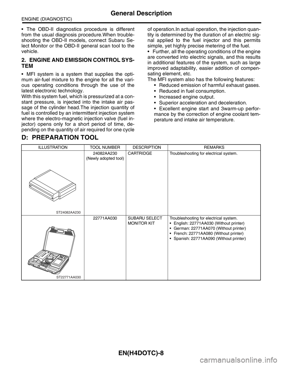
ILLUSTRATION TOOL NUMBER DESCRIPTION REMARKS
24082AA230
(Newly adopted tool)CARTRIDGE Troubleshooting for electrical system.
22771AA030 SUBARU SELECT
MONITOR KITTroubleshooting for electrical system.
English: 22771AA030 (Without printer)
German: 22771AA070 (Without printer)
French: 22771AA080 (Without printer)
Spanish: 22771AA090 (Without printer)
ST24082AA230
ST22771AA030