Page 1928 of 2870

EN(H4DOTC)-295
ENGINE (DIAGNOSTIC)
General Diagnostic Table
20.General Diagnostic Table
A: INSPECTION
1. ENGINE
NOTE:
Malfunction of parts other than those listed is also possible.
General.>
Symptom Problem parts
1. Engine stalls during idling.1) Idle air control solenoid valve
2) Manifold absolute pressure sensor
3) Mass air flow and intake air temperature sensor
4) Ignition parts (*1)
5) Engine coolant temperature sensor (*2)
6) Crankshaft position sensor (*3)
7) Camshaft position sensor (*3)
8) Fuel injection parts (*4)
2. Rough idling1) Idle air control solenoid valve
2) Manifold absolute pressure sensor
3) Mass air flow and intake air temperature sensor
4) Engine coolant temperature sensor (*2)
5) Ignition parts (*1)
6) Air intake system (*5)
7) Fuel injection parts (*4)
8) Throttle position sensor
9) Crankshaft position sensor (*3)
10) Camshaft position sensor (*3)
11) Oxygen sensor
12) Fuel pump and fuel pump relay
3. Engine does not return to idle.1) Idle air control solenoid valve
2) Engine coolant temperature sensor
3) Accelerator cable (*6)
4) Throttle position sensor
5) Manifold absolute pressure sensor
6) Mass air flow sensor
4. Poor acceleration1) Manifold absolute pressure sensor
2) Mass air flow and intake air temperature sensor
3) Throttle position sensor
4) Fuel injection parts (*4)
5) Fuel pump and fuel pump relay
6) Engine coolant temperature sensor (*2)
7) Crankshaft position sensor (*3)
8) Camshaft position sensor (*3)
9) A/C switch and A/C cut relay
10) Engine torque control signal circuit
11) Ignition parts (*1)
5. Engine stalls or engine sags or hesitates at
acceleration.1) Manifold absolute pressure sensor
2) Mass air flow and intake air temperature sensor
3) Engine coolant temperature sensor (*2)
4) Crankshaft position sensor (*3)
5) Camshaft position sensor (*3)
6) Purge control solenoid valve
7) Fuel injection parts (*4)
8) Throttle position sensor
9) Fuel pump and fuel pump relay
Page 1929 of 2870

EN(H4DOTC)-296
ENGINE (DIAGNOSTIC)
General Diagnostic Table
*1: Check ignition coil & ignitor ASSY and spark plug.
*2: Indicate the symptom occurring only in cold temperatures.
*3: Ensure the secure installation.
*4: Check fuel injector, fuel pressure regulator and fuel filter.
*5: Inspect air leak in air intake system.
*6: Adjust accelerator cable. 6. Surging1) Manifold absolute pressure sensor
2) Mass air flow and intake air temperature sensor
3) Engine coolant temperature sensor (*2)
4) Crankshaft position sensor (*3)
5) Camshaft position sensor (*3)
6) Fuel injection parts (*4)
7) Throttle position sensor
8) Fuel pump and fuel pump relay
7. Spark knock1) Manifold absolute pressure sensor
2) Mass air flow and intake air temperature sensor
3) Engine coolant temperature sensor
4) Knock sensor
5) Fuel injection parts (*4)
6) Fuel pump and fuel pump relay
8. After burning in exhaust system1) Manifold absolute pressure sensor
2) Mass air flow and intake air temperature sensor
3) Engine coolant temperature sensor (*2)
4) Fuel injection parts (*4)
5) Fuel pump and fuel pump relay Symptom Problem parts
Page 1931 of 2870

FUEL INJECTION (FUEL SYSTEM)
FU(H4DOTC 2.5)
Page
1. General Description ....................................................................................2
2. Throttle Body .............................................................................................13
3. Intake Manifold ..........................................................................................14
4. Engine Coolant Temperature Sensor........................................................26
5. Crankshaft Position Sensor.......................................................................27
6. Camshaft Position Sensor.........................................................................28
7. Knock Sensor ............................................................................................29
8. Mass Air Flow and Intake Air Temperature Sensor ..................................30
9. Manifold Absolute Pressure Sensor ..........................................................31
10. Fuel Injector ..............................................................................................32
11. Tumble Generator Valve Assembly ..........................................................33
12. Tumble Generator Valve Actuator.............................................................34
13. Wastegate Control Solenoid Valve ...........................................................35
14. Front Oxygen (A/F) Sensor .......................................................................36
15. Rear Oxygen Sensor.................................................................................38
16. Exhaust Temperature Sensor ...................................................................40
17. Engine Control Module (ECM) ..................................................................41
18. Main Relay ................................................................................................42
19. Fuel Pump Relay.......................................................................................43
20. Fuel Pump Control Unit .............................................................................44
21. Fuel ...........................................................................................................45
22. Fuel Tank ..................................................................................................46
23. Fuel Filler Pipe ..........................................................................................48
24. Fuel Pump .................................................................................................52
25. Fuel Level Sensor .....................................................................................54
26. Fuel Sub Level Sensor ..............................................................................55
27. Fuel Filter ..................................................................................................57
28. Fuel Cut Valve...........................................................................................58
29. Fuel Damper Valve ...................................................................................59
30. Fuel Delivery, Return and Evaporation Lines............................................60
31. Fuel System Trouble in General ...............................................................63
Page 1945 of 2870
FU(H4DOTC 2.5)-15
FUEL INJECTION (FUEL SYSTEM)
Intake Manifold
(6) Place the power steering pump on the right
side wheel apron.
12) Disconnect the emission hose from the PCV
valve.
13) Disconnect the engine coolant hoses from the
throttle body.
14) Disconnect the brake booster hose.15) Disconnect the pressure hose from the intake
duct.
16) Disconnect the engine harness connectors
from the bulkhead harness connectors.
17) Disconnect the connectors from the engine cool-
ant temperature sensor (A), oil pressure switch (B)
and crankshaft position sensor (C).
FU-00021
FU-00022
FU-01074
FU-00023
FU-00024
FU-00025
FU-00026
(A)
(B)
(C)
FU-00027
Page 1956 of 2870
FU(H4DOTC 2.5)-26
FUEL INJECTION (FUEL SYSTEM)
Engine Coolant Temperature Sensor
4. Engine Coolant Temperature
Sensor
A: REMOVAL
1) Disconnect the ground cable from battery.
2) Remove the generator.
REMOVAL, Generator.>
3) Drain the engine coolant.
DRAINING OF ENGINE COOLANT, REPLACE-
MENT, Engine Coolant.>
4) Disconnect the connector from the engine cool-
ant temperature sensor.
5) Remove the engine coolant temperature sensor.
B: INSTALLATION
Install in the reverse order of removal.
Tightening torque:
18 N·m (1.8 kgf-m, 13.3 ft-lb)
FU-00009
FU-00055
Page 2031 of 2870

EN(H4DOTC 2.5)-7
ENGINE (DIAGNOSTIC)
General Description
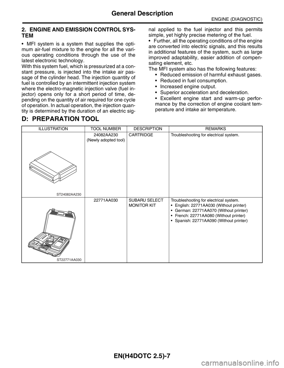
2. ENGINE AND EMISSION CONTROL SYS-
TEM
MFI system is a system that supplies the opti-
mum air-fuel mixture to the engine for all the vari-
ous operating conditions through the use of the
latest electronic technology.
With this system fuel, which is pressurized at a con-
stant pressure, is injected into the intake air pas-
sage of the cylinder head. The injection quantity of
fuel is controlled by an intermittent injection system
where the electro-magnetic injection valve (fuel in-
jector) opens only for a short period of time, de-
pending on the quantity of air required for one cycle
of operation. In actual operation, the injection quan-
tity is determined by the duration of an electric sig-nal applied to the fuel injector and this permits
simple, yet highly precise metering of the fuel.
Further, all the operating conditions of the engine
are converted into electric signals, and this results
in additional features of the system, such as large
improved adaptability, easier addition of compen-
sating element, etc.
The MFI system also has the following features:
Reduced emission of harmful exhaust gases.
Reduced in fuel consumption.
Increased engine output.
Superior acceleration and deceleration.
Excellent engine start and warm-up perfor-
mance by the correction of engine coolant tem-
perature and intake air temperature.
D: PREPARATION TOOL
ILLUSTRATION TOOL NUMBER DESCRIPTION REMARKS
24082AA230
(Newly adopted tool)CARTRIDGE Troubleshooting for electrical system.
22771AA030 SUBARU SELECT
MONITOR KITTroubleshooting for electrical system.
English: 22771AA030 (Without printer)
German: 22771AA070 (Without printer)
French: 22771AA080 (Without printer)
Spanish: 22771AA090 (Without printer)
ST24082AA230
ST22771AA030
Page 2033 of 2870
EN(H4DOTC 2.5)-9
ENGINE (DIAGNOSTIC)
Electrical Component Location
SENSOR
(1) Manifold absolute pressure sen-
sor(3) Electronic throttle control (7) Mass air flow and intake air tem-
perature sensor
(4) Knock sensor
(2) Engine coolant temperature sen-
sor(5) Camshaft position sensor (8) Tumble generator valve position
sensor
(6) Crankshaft position sensor
EN-02008
(1)
(7) (6) (4) (8)(2)
(3)(5)
Page 2041 of 2870

EN(H4DOTC 2.5)-17
ENGINE (DIAGNOSTIC)
Engine Control Module (ECM) I/O Signal
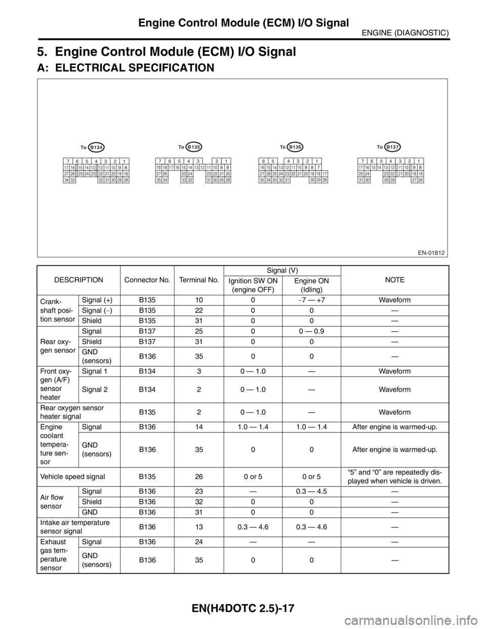
5. Engine Control Module (ECM) I/O Signal
A: ELECTRICAL SPECIFICATION
DESCRIPTION Connector No. Terminal No.Signal (V)
NOTE
Ignition SW ON
(engine OFF)Engine ON
(Idling)
Crank-
shaft posi-
tion sensorSignal (+) B135 10 0−7 — +7 Waveform
Signal (−) B135 22 0 0 —
Shield B135 31 0 0 —
Rear oxy-
gen sensorSignal B137 25 0 0 — 0.9 —
Shield B137 31 0 0 —
GND
(sensors)B136 35 0 0 —
Fr o nt ox y-
gen (A/F)
sensor
heaterSignal 1 B134 3 0 — 1.0 — Waveform
Signal 2 B134 2 0 — 1.0 — Waveform
Rear oxygen sensor
heater signalB135 2 0 — 1.0 — Waveform
Engine
coolant
tempera-
ture sen-
sorSignal B136 14 1.0 — 1.4 1.0 — 1.4 After engine is warmed-up.
GND
(sensors)B136 35 0 0 After engine is warmed-up.
Vehicle speed signal B135 26 0 or 5 0 or 5“5” and “0” are repeatedly dis-
played when vehicle is driven.
Air flow
sensorSignal B136 23 — 0.3 — 4.5 —
Shield B136 32 0 0 —
GND B136 31 0 0 —
Intake air temperature
sensor signalB136 13 0.3 — 4.6 0.3 — 4.6 —
Exhaust
gas tem-
perature
sensorSignal B136 24 — — —
GND
(sensors)B136 35 0 0 —
EN-01812
B134
5 6 7
8 21
9 43
10
24 2223 2511 12 13 14 15
26 27
28 16 17
18 19 20 21
33 34 29
32 3031
B136
5 6
7 8 21
9 43
10
24 2223 2511 12 13
14 15
26 27
28 16
17 18 19 20 21
33 3429
3230
31 35
B135
5 6 7
8 21
9 43
10
24 2223 2511 12 13 14 15
26 27
28 16 17 18 19
20 21
29 30 31 32 33 34 35
B137
5 6 7
8 21
9 43
10
22 2311 12 13 14 15
24 25
26 16 17
18 19 20 21
27 28 29 30 31
To
To To
To