2004 SUBARU FORESTER coolant temperature
[x] Cancel search: coolant temperaturePage 759 of 2870
PM-22
PERIODIC MAINTENANCE SERVICE
Engine Coolant
2. RELATIONSHIP OF SUBARU COOLANT
CONCENTRATION AND FREEZING TEM-
PERATURE
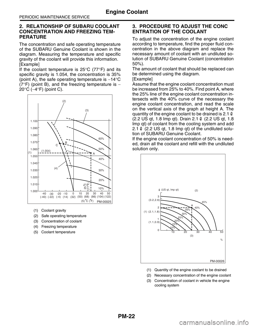
The concentration and safe operating temperature
of the SUBARU Genuine Coolant is shown in the
diagram. Measuring the temperature and specific
gravity of the coolant will provide this information.
[Example]
If the coolant temperature is 25°C (77°F) and its
specific gravity is 1.054, the concentration is 35%
(point A), the safe operating temperature is −14°C
(7°F) (point B), and the freezing temperature is −
20°C (−4°F) (point C).
3. PROCEDURE TO ADJUST THE CONC
ENTRATION OF THE COOLANT
To adjust the concentration of the engine coolant
according to temperature, find the proper fluid con-
centration in the above diagram and replace the
necessary amount of coolant with an undiluted so-
lution of SUBARU Genuine Coolant (concentration
50%).
The amount of coolant that should be replaced can
be determined using the diagram.
[Example]
Assume that the engine coolant concentration must
be increased from 25% to 40%. Find point A, where
the 25% line of the engine coolant concentration in-
tersects with the 40% curve of the necessary the
engine coolant concentration, and read the scale
on the vertical axis of the graph at height A. The
quantity of the engine coolant to be drained is 2.12
(2.2 US qt, 1.8 Imp qt). Drain 2.12 (2.2 US qt, 1.8
Imp qt) of coolant from the cooling system and add
2.12 (2.2 US qt, 1.8 Imp qt) of the undiluted solu-
tion of SUBARU Genuine Coolant.
If the engine coolant concentration of 50% is need-
ed, drain all the coolant and refill with the undiluted
solution only.
(1) Coolant gravity
(2) Safe operating temperature
(3) Concentration of coolant
(4) Freezing temperature
(5) Coolant temperature
PM-00025
60%
(1.054)
1.000 1.010 1.020
1.030
1.040
1.050
1.060
1.070 1.080 1.090
1.100
(5) (4)(3) (2)
(1)B
A C
-40
(-40) (-22)(-4)
(14)(32)(50) (68) (86)
( F)(104) (122) -30-20 -1001020304050
(77 F)
50%
40%
30%
20%
25 C10%
C
(1) Quantity of the engine coolant to be drained
(2) Necessary concentration of the engine coolant
(3) Concentration of coolant in vehicle the engine
cooling system
PM-00026
10 0 12 3
(1.1,0.9) (2.1,1.8)(3.2,2.6)
10%15%25%
20%30%35%40%45%
A
20 30 40 50
% (3)(2)
(1)(US qt, Imp qt)
Page 783 of 2870

FUEL INJECTION (FUEL SYSTEM)
FU(H4SO)
Page
1. General Description ....................................................................................2
2. Throttle Body .............................................................................................13
3. Intake Manifold ..........................................................................................14
4. Engine Coolant Temperature Sensor........................................................25
5. Crankshaft Position Sensor.......................................................................26
6. Camshaft Position Sensor.........................................................................27
7. Knock Sensor ............................................................................................28
8. Throttle Position Sensor ............................................................................29
9. Manifold Absolute Pressure Sensor ..........................................................31
10. Intake Air Temperature Sensor .................................................................32
11. Idle Air Control Solenoid Valve .................................................................33
12. EGR Valve ................................................................................................34
13. Fuel Injector ..............................................................................................35
14. Front Oxygen (A/F) Sensor .......................................................................40
15. Rear Oxygen Sensor.................................................................................42
16. Engine Control Module (ECM) ..................................................................44
17. Main Relay ................................................................................................45
18. Fuel Pump Relay.......................................................................................46
19. Fuel ...........................................................................................................47
20. Fuel Tank ..................................................................................................48
21. Fuel Filler Pipe ..........................................................................................51
22. Fuel Pump .................................................................................................55
23. Fuel Level Sensor .....................................................................................57
24. Fuel Sub Level Sensor ..............................................................................58
25. Fuel Filter ..................................................................................................60
26. Fuel Cut Valve...........................................................................................61
27. Fuel Damper Valve ...................................................................................62
28. Fuel Delivery, Return and Evaporation Lines............................................63
29. Fuel System Trouble in General ...............................................................66
Page 797 of 2870
FU(H4SO)-15
FUEL INJECTION (FUEL SYSTEM)
Intake Manifold
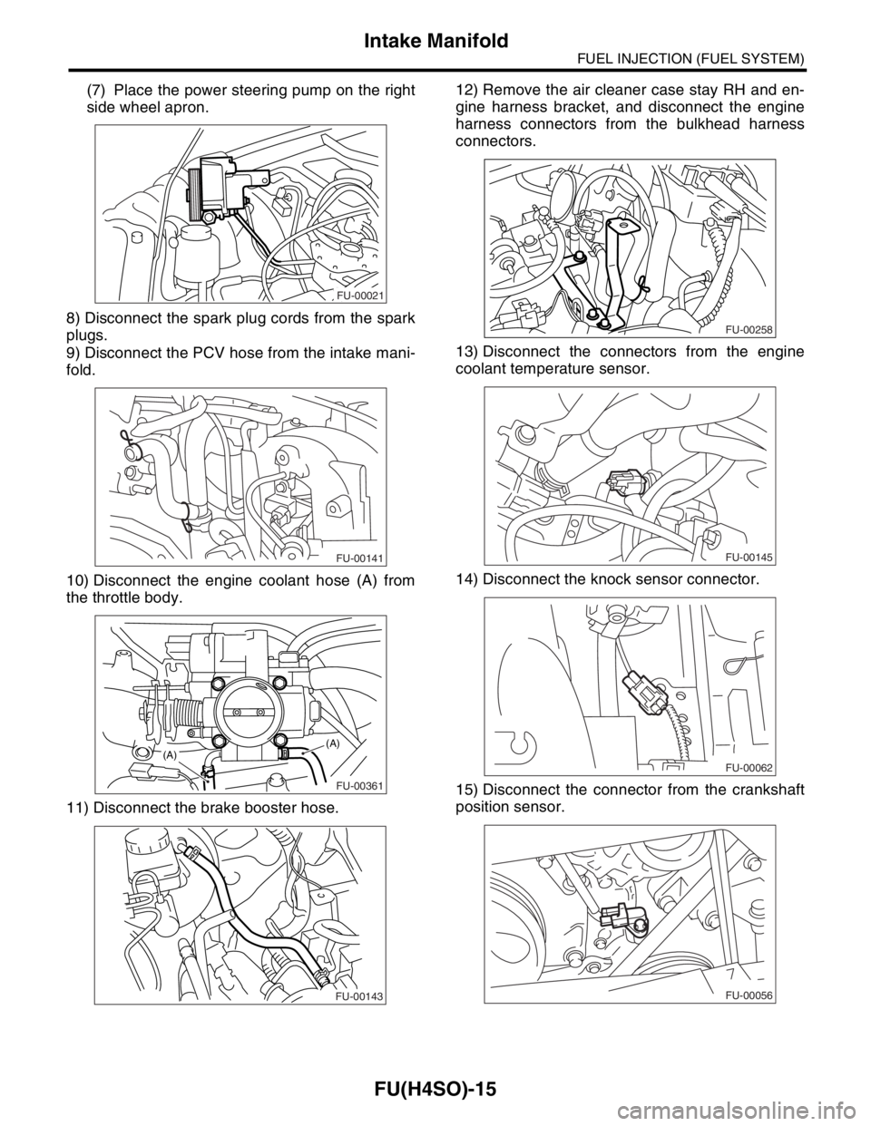
(7) Place the power steering pump on the right
side wheel apron.
8) Disconnect the spark plug cords from the spark
plugs.
9) Disconnect the PCV hose from the intake mani-
fold.
10) Disconnect the engine coolant hose (A) from
the throttle body.
11) Disconnect the brake booster hose.12) Remove the air cleaner case stay RH and en-
gine harness bracket, and disconnect the engine
harness connectors from the bulkhead harness
connectors.
13) Disconnect the connectors from the engine
coolant temperature sensor.
14) Disconnect the knock sensor connector.
15) Disconnect the connector from the crankshaft
position sensor.
FU-00021
FU-00141
FU-00361
(A)(A)
FU-00143
FU-00258
FU-00145
FU-00062
FU-00056
Page 799 of 2870
FU(H4SO)-17
FUEL INJECTION (FUEL SYSTEM)
Intake Manifold
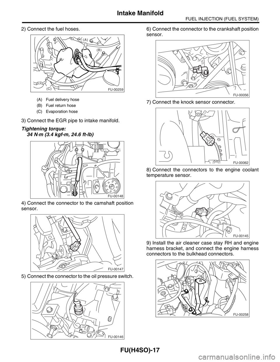
2) Connect the fuel hoses.
3) Connect the EGR pipe to intake manifold.
Tightening torque:
34 N
⋅m (3.4 kgf-m, 24.6 ft-lb)
4) Connect the connector to the camshaft position
sensor.
5) Connect the connector to the oil pressure switch.6) Connect the connector to the crankshaft position
sensor.
7) Connect the knock sensor connector.
8) Connect the connectors to the engine coolant
temperature sensor.
9) Install the air cleaner case stay RH and engine
harness bracket, and connect the engine harness
connectors to the bulkhead connectors.
(A) Fuel delivery hose
(B) Fuel return hose
(C) Evaporation hose
(B) (A)
(C)
FU-00259
FU-00148
FU-00147
FU-00146
FU-00056
FU-00062
FU-00145
FU-00258
Page 807 of 2870
FU(H4SO)-25
FUEL INJECTION (FUEL SYSTEM)
Engine Coolant Temperature Sensor
4. Engine Coolant Temperature
Sensor
A: REMOVAL
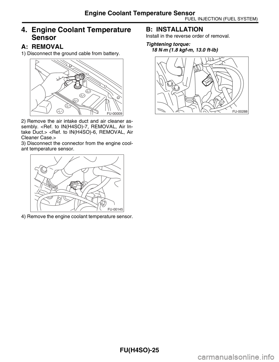
1) Disconnect the ground cable from battery.
2) Remove the air intake duct and air cleaner as-
sembly.
3) Disconnect the connector from the engine cool-
ant temperature sensor.
4) Remove the engine coolant temperature sensor.
B: INSTALLATION
Install in the reverse order of removal.
Tightening torque:
18 N
⋅m (1.8 kgf-m, 13.0 ft-lb)
FU-00009
FU-00145
FU-00288
Page 985 of 2870

CO(H4SO)-2
COOLING
General Description
1. General Description
A: SPECIFICATION
ModelNon-turbo Turbo
Cooling system Electric fan+Forced engine coolant circulation system
Total engine coolant capacity2(US qt, Imp qt)2.0L with ATF warmer:
Approx. 6.9 (7.29, 6.07)
2.0L AT:
Approx. 6.5 (6.87, 5.72)
2.0L MT:
Approx. 6.6 (6.98, 5.81)
2.5L AT:
Approx. 6.8 (7.19, 5.98)
2.5L MT:
Approx. 6.9 (7.29, 6.07)AT :
Approx. 7.3 (7.71, 6.42)
MT with oil cooler:
Approx. 7.3 (7.71, 6.42)
MT without oil cooler:
Approx. 7.4 (7.82, 6.51)
Water pumpType Centrifugal impeller type
Discharge perfor-
mance IDischarge 202 (5.3 US gal, 4.4 Imp gal)/min.
Pump speed — Discharge
pressure760 rpm — 2.9 kPa (0.3 mAq)
Engine coolant temperature 85°C (185°F)
Discharge perfor-
mance IIDischarge 1002 (26.4 US gal, 22.0 Imp gal)/min.
Pump speed — Discharge
pressure3,000 rpm — 49.0 kPa (5.0 mAq)
Engine coolant temperature 85°C (185°F)
Discharge perfor-
mance IIIDischarge 2002 (52.8 US gal, 44.0 Imp gal)/min.
Pump speed — Discharge
pressure6,000 rpm — 225.4 kPa (23.0 mAq)
Engine coolant temperature 85°C (185°F)
Impeller diameter 76 mm (2.99 in)
Number of impeller vanes 8
Pump pulley diameter 60 mm (2.36 in)
Clearance between
impeller and caseStandard 0.5 — 0.7 mm (0.020 — 0.028 in)
Limit 1.0 mm (0.039 in)
“Thrust” runout of impeller end 0.5 mm (0.020 in)
ThermostatType Wax pellet type
Starts to open 80 — 84°C (176 — 183°F) 76 — 80°C (169 — 176°F)
Fully opened 95°C (203°F) 91°C (196°F)
Valve lift 9.0 mm (0.354 in) or more
Valve bore 35 mm (1.38 in)
Radiator fanMotorMain fan 70 W2.0L AT (K4
★1) : 70 W
2.0L AT (EC, EK★1) :
120 W
2.0 L MT: 70 W
2.5 L: 120 W
Sub fan 70 W2.0L AT (K4
★1) : 70 W
2.0L AT (EC, EK★1) :
120 W
2.0 L MT: 70 W
2.5 L: 120 W
Fan diameter×Blade320 mm (11.81 in)×5 (main fan)
320 mm (11.81 in)×7 (sub fan)
Page 997 of 2870

CO(H4SO)-14
COOLING
Radiator Fan System
B: INSPECTION
DETECTING CONDITION:
Engine coolant temperature is above 95°C (203°F).
Vehicle speed is below 19 km/h (12 MPH).
TROUBLE SYMPTOM:
Radiator main fan and sub fan does not rotate under the above conditions.
Step Check Yes No
1 CHECK OPERATION OF RADIATOR FAN.
1) Connect the test mode connector.
2) Turn the ignition switch to ON.
3) Using Subaru Select Monitor, check the
compulsory operation of radiator fan relay.
N
OTE:
With Subaru Select Monitor
When checking the compulsory operation of
radiator fan, the radiator main and sub fan
repeat the rotation in order of following: low
speed rotation → high speed rotation → off.
Subaru Select Monitor
Refer to Compulsory Valve Operation Check
Mode for detail procedures.
Check Mode.>Do the radiator main and sub
fan rotate at low speed?Go to step 2.Go to step 3.
2 CHECK OPERATION OF RADIATOR FAN.
1) Connect the test mode connector.
2) Turn the ignition switch to ON.
3) Using Subaru Select Monitor, check the
compulsory operation of radiator fan relay.
N
OTE:
With Subaru Select Monitor
When checking the compulsory operation of
radiator fan, the radiator main and sub fan
repeat the rotation in order of following: low
speed rotation → high speed rotation → off.
Subaru Select Monitor
Refer to Compulsory Valve Operation Check
Mode for detail procedures.
Check Mode.>Do the radiator main and sub
fan rotate at high speed?Radiator main fan
system is okay.Go to step 32.
3 CHECK POWER SUPPLY TO MAIN FAN RE-
LAY.
1) Turn the ignition switch to OFF.
2) Remove the fan relay 1 from A/C relay
holder.
3) Measure the voltage between main fan
relay terminal and chassis ground.
Connector & terminal
(F27) No. 31 (+) — Chassis ground (
−):Is the voltage more than 10 V? Go to step 4.Go to step 5.
4 CHECK POWER SUPPLY TO MAIN FAN RE-
LAY.
1) Turn the ignition switch to ON.
2) Measure the voltage between main fan
relay terminal and chassis ground.
Connector & terminal
(F27) No. 34 (+) — Chassis ground (
−):Is the voltage more than 10 V? Go to step 8.Go to step 7.
5 CHECK FUSE.
1) Remove the fuse from A/C relay holder.
2) Check the condition of fuse.Is the fuse blown out? Replace the fuse. Go to step 6.
Page 1003 of 2870
CO(H4SO)-20
COOLING
Engine Coolant
B: INSPECTION
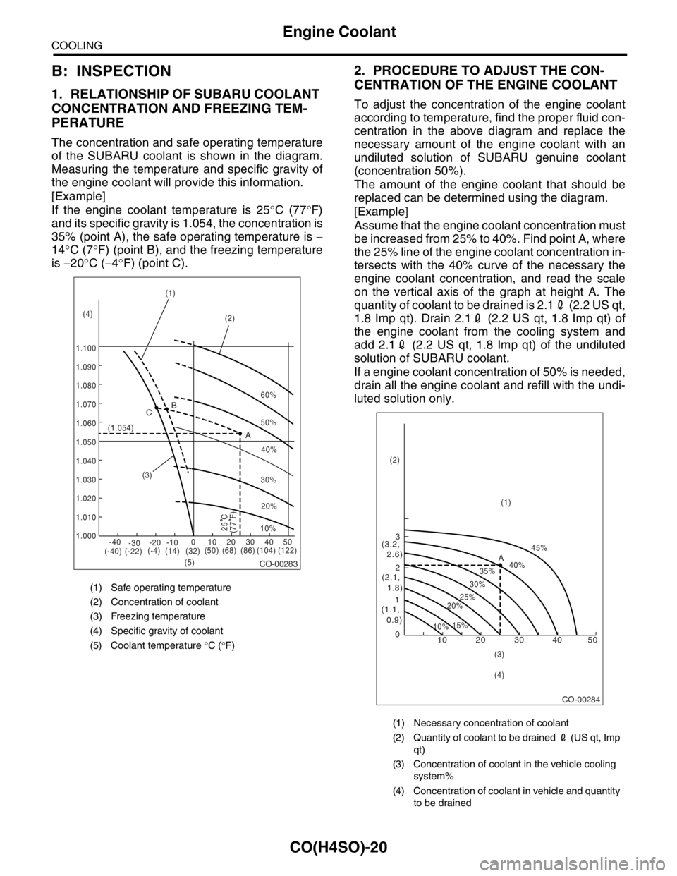
1. RELATIONSHIP OF SUBARU COOLANT
CONCENTRATION AND FREEZING TEM-
PERATURE
The concentration and safe operating temperature
of the SUBARU coolant is shown in the diagram.
Measuring the temperature and specific gravity of
the engine coolant will provide this information.
[Example]
If the engine coolant temperature is 25°C (77°F)
and its specific gravity is 1.054, the concentration is
35% (point A), the safe operating temperature is −
14°C (7°F) (point B), and the freezing temperature
is −20°C (−4°F) (point C).
2. PROCEDURE TO ADJUST THE CON-
CENTRATION OF THE ENGINE COOLANT
To adjust the concentration of the engine coolant
according to temperature, find the proper fluid con-
centration in the above diagram and replace the
necessary amount of the engine coolant with an
undiluted solution of SUBARU genuine coolant
(concentration 50%).
The amount of the engine coolant that should be
replaced can be determined using the diagram.
[Example]
Assume that the engine coolant concentration must
be increased from 25% to 40%. Find point A, where
the 25% line of the engine coolant concentration in-
tersects with the 40% curve of the necessary the
engine coolant concentration, and read the scale
on the vertical axis of the graph at height A. The
quantity of coolant to be drained is 2.12 (2.2 US qt,
1.8 Imp qt). Drain 2.12 (2.2 US qt, 1.8 Imp qt) of
the engine coolant from the cooling system and
add 2.12 (2.2 US qt, 1.8 Imp qt) of the undiluted
solution of SUBARU coolant.
If a engine coolant concentration of 50% is needed,
drain all the engine coolant and refill with the undi-
luted solution only.
(1) Safe operating temperature
(2) Concentration of coolant
(3) Freezing temperature
(4) Specific gravity of coolant
(5) Coolant temperature °C (°F)
CO-00283
60%
(1.054)
1.000 1.010 1.020
1.030
1.040
1.050
1.060
1.070 1.080 1.090
1.100(1)
(2)
(3)
(5) (4)B
A C
-40
(-40) (-22)(-4)
(14)(32)(50) (68) (86) (104) (122) -30-20 -1001020304050
(77 F)
50%
40%
30%
20%
25 C10%
(1) Necessary concentration of coolant
(2) Quantity of coolant to be drained 2 (US qt, Imp
qt)
(3) Concentration of coolant in the vehicle cooling
system%
(4) Concentration of coolant in vehicle and quantity
to be drained
CO-00284
10 0 12 3
(1.1,
0.9)(2.1,
1.8) (3.2,
2.6)
10%15%25%
20%30%35%40%45%
A
20 30 40 50
(1) (2)
(3)
(4)