2004 SUBARU FORESTER coolant temperature
[x] Cancel search: coolant temperaturePage 1135 of 2870

EN(H4SO)-37
ENGINE (DIAGNOSTIC)
Inspection Mode
12.Inspection Mode
A: OPERATION
Perform the diagnosis on the “Diagnosis Trouble Codes (DTC) List” below.
Refer to the item of drive cycle when perform the diagnosis not on the “Diagnosis Trouble Codes (DTC) List”
below.
DTC Item
P0030 HO2S Heater Control Circuit (Bank 1 Sensor 1)
P0031 HO2S Heater Control Circuit Low (Bank 1 Sensor 1)
P0032 HO2S Heater Control Circuit High (Bank 1 Sensor 1)
P0037 HO2S Heater Control Circuit Low (Bank 1 Sensor 2)
P0038 HO2S Heater Control Circuit High (Bank 1 Sensor 2)
P0068 Manifold Pressure Sensor Range/Performance
P0107 Manifold Absolute Pressure/Barometric Pressure Circuit Low Input
P0108 Manifold Absolute Pressure/Barometric Pressure Circuit High Input
P0112 Intake Air Temperature Circuit Low Input
P0113 Intake Air Temperature Circuit High Input
P0117 Engine Coolant Temperature Circuit Low Input
P0118 Engine Coolant Temperature Circuit High Input
P0122 Throttle/Pedal Position Sensor/Switch “A” Circuit Low Input
P0123 Throttle/Pedal Position Sensor/Switch “A” Circuit High Input
P0129 Barometric Pressure Too Low
P0131 O
2 Sensor Circuit Low Voltage (Bank 1 Sensor 1)
P0132 O
2 Sensor Circuit High Voltage (Bank 1 Sensor 1)
P0134 O
2 Sensor Circuit No Activity Detected (Bank 1 Sensor 1)
P0137 O
2 Sensor Circuit Low Voltage (Bank 1 Sensor 2)
P0138 O
2 Sensor Circuit High Voltage (Bank 1 Sensor 2)
P0327 Knock Sensor 1 Circuit Low Input (Bank 1 or Single Sensor)
P0328 Knock Sensor 1 Circuit High Input (Bank 1 or Single Sensor)
P0335 Crankshaft Position Sensor “A” Circuit
P0336 Crankshaft Position Sensor “A” Circuit Range/Performance
P0340 Camshaft Position Sensor “A” Circuit (Bank 1 or Single Sensor)
P0341 Camshaft Position Sensor “A” Circuit Range/Performance (Bank 1 or Single Sensor)
P0458 Evaporative Emission Control System Purge Control Valve Circuit Low
P0462 Fuel Level Sensor Circuit Low Input
P0463 Fuel Level Sensor Circuit High Input
P0502 Vehicle Speed Sensor Circuit Low Input
P0503 Vehicle Speed Sensor Intermittent/Erratic/High
P0512 Starter Request Circuit
P0513 Incorrect Immobilizer Key
P0519 Idle Control System Malfunction (Fail-Safe)
P0565 Cruise Control On Signal
P0604 Internal Control Module Random Access Memory (RAM) Error
P0703 Torque Converter/Brake Switch “B” Circuit
P0705 Transmission Range Sensor Circuit (PRNDL Input)
P0710 Transmission Fluid Temperature Sensor Circuit
P0716 Torque converter turbine speed sensor
P0720 AT Vehicle Speed Sensor Circuit Malfunction
P0726 Engine Speed Input Circuit Malfunction
P0731 Gear 1 Incorrect Ratio
P0732 Gear 2 Incorrect Ratio
P0733 Gear 3 Incorrect Ratio
Page 1140 of 2870

EN(H4SO)-42
ENGINE (DIAGNOSTIC)
Drive Cycle
13.Drive Cycle
A: OPERATION
There are three driving patterns on diagnosis. Fol-
lowing trouble can be diagnosed with driving spec-
ified patterns. After repair the following trouble, be
sure to check that the trouble is cleared correctly by
the driving specified patterns.
1. PREPARATION FOR DRIVE CYCLE
1) Check battery voltage is more than 12 V and fuel
remains half [20 — 402 (5.3 — 10.6 US gal, 4.4 —
8.8 Imp gal)].2) After clearing the memory, check for any remain-
ing unresolved trouble data.
3) Separate the test mode connector.
NOTE:
Be sure to perform the diagnosis after idling from
starting the cooled engine except when the engine
coolant temperature is specified.
Perform the diagnosis twice when the DTC is
marked with *. After the completion of first diagno-
sis, stop the engine and perform the second diag-
nosis on same condition.
2. DRIVE THE VEHICLE 20 MINUTES AT THE SPEED OF 80 KM/H (50 MPH), AND THEN IDLE
THE ENGINE 1 MINUTE.
3. 10 MINUTES IDLING
NOTE:
Drive the vehicle more than 4 km/h (6 MPH) before diagnosis.
DTC Item On condition
*P0030 HO2S Heater Control Circuit (Bank 1 Sensor 1) —
*P0111Intake Air Temperature Sensor Circuit Range/Per-
formance ProblemEngine coolant temperature at start is less than 30°C (86°F)
*P0125Insufficient coolant temperature for closed loop
fuel controlEngine coolant temperature at start is less than 20°C (68°F)
*P0130O
2 Sensor Circuit (Bank 1 Sensor 1)
—
*P0133O
2 Sensor Circuit Slow Response (Bank 1 Sensor
1)—
*P0420Catalyst System Efficiency Below Threshold
(Bank 1)—
P0459Evaporative Emission Control System Purge Con-
trol Valve Circuit High—
*P0461 Fuel Level Sensor Circuit Range/Performance —
*P0464 Fuel Level Sensor Circuit Intermittent —
*P1137O
2 Sensor Circuit (Bank 1 Sensor 1)
—
DTC Item On condition
*P0483 Cooling Fan Rationality Check —
*P0506 Idle Control System RPM Lower Than Expected —
*P0507 Idle Control System RPM Higher Than Expected —
Page 1170 of 2870

EN(H4SO)-72
ENGINE (DIAGNOSTIC)
List of Diagnostic Trouble Code (DTC)
18.List of Diagnostic Trouble Code (DTC)
A: LIST
DTC Item NOTE
P0030 HO2S Heater Control Circuit (Bank 1
Sensor 1)
(DTC).>
P0031 HO2S Heater Control Circuit Low
(Bank 1 Sensor 1)
Code (DTC).>
P0032 HO2S Heater Control Circuit High
(Bank 1 Sensor 1)
Code (DTC).>
P0037 HO2S Heater Control Circuit Low
(Bank 1 Sensor 2)
Code (DTC).>
P0038 HO2S Heater Control Circuit High
(Bank 1 Sensor 2)
Code (DTC).>
P0068 Manifold Pressure Sensor Range/
Pe r fo r ma nc e
Code (DTC).>
P0107 Manifold Absolute Pressure/Baro-
metric Pressure Circuit Low Input
with Diagnostic Trouble Code (DTC).>
P0108 Manifold Absolute Pressure/Baro-
metric Pressure Circuit High Input
with Diagnostic Trouble Code (DTC).>
P0111 Intake Air Temperature Circuit
Range/Performance
Code (DTC).>
P0112 Intake Air Temperature Circuit Low
Input
(DTC).>
P0113 Intake Air Temperature Circuit High
Input
(DTC).>
P0117 Engine Coolant Temperature Circuit
Low Input
(DTC).>
P0118 Engine Coolant Temperature Circuit
High Input
(DTC).>
P0121 Throttle/Pedal Position Sensor/
Switch “A” Circuit Range/Perfor-
mance
dure with Diagnostic Trouble Code (DTC).>
P0122 Throttle/Pedal Position Sensor/
Switch “A” Circuit Low Input
nostic Trouble Code (DTC).>
P0123 Throttle/Pedal Position Sensor/
Switch “A” Circuit High Input
nostic Trouble Code (DTC).>
P0125 Insufficient Coolant Temperature For
Closed Loop Fuel Control
Diagnostic Trouble Code (DTC).>
P0129 Barometric Pressure Too Low
Page 1189 of 2870

EN(H4SO)-91
ENGINE (DIAGNOSTIC)
Diagnostic Procedure with Diagnostic Trouble Code (DTC)
Step Check Yes No
1 CHECK ANY OTHER DTC ON DISPLAY.Is any other DTC displayed? Inspect DTC using
“List of Diagnostic
Trouble Code
(DTC)”.
of Diagnostic Trou-
ble Code (DTC).>Go to step 2.
2 CHECK AIR INTAKE SYSTEM.Are there holes, loose bolts or
disconnection of hose on air
intake system?Repair air intake
system.Go to step 3.
3 CHECK PRESSURE SENSOR.
1) Start and warm-up the engine until engine
coolant temperature is greater than 60°C
(140°F).
2) Shift the select lever in the “P” or “N” range.
3) Turn the A/C switch to OFF.
4) Turn all accessory switches to OFF.
5) Read the data of manifold absolute pres-
sure sensor signal using Subaru Select Moni-
tor or OBD-II general scan tool.
N
OTE:
Subaru Select Monitor
For detailed operation procedure, refer to the
“READ CURRENT DATA FOR ENGINE”.
OBD-II general scan tool
For detailed operation procedures, refer to the
OBD-II General Scan Tool Operation Manual.Is the measured value at Igni-
tion ON: 73.3 — 106.6 kPa
(550 — 800 mmHg, 21.65 —
31.50 inHg) Idling: 20.0 — 46.7
kPa (150 — 310 mmHg, 5.91
— 12.20 inHg)?Go to step 4.Replace the mani-
fold absolute pres-
sure sensor.
Manifold Absolute
Pressure Sensor.>
4 CHECK THROTTLE POSITION.
Read the data of throttle position signal using
Subaru Select Monitor or OBD-II general scan
tool.
NOTE:
Subaru Select Monitor
For detailed operation procedure, refer to the
“READ CURRENT DATA FOR ENGINE”.
OBD-II general scan tool
For detailed operation procedures, refer to the
OBD-II General Scan Tool Operation Manual.Is the value less than 5% when
the throttle fully closed?Go to step 5.Adjust or replace
the throttle posi-
tion sensor.
Throttle Position
Sensor.>
5 CHECK THROTTLE POSITION.Is the value more than 85%
when the throttle fully opens?Replace the mani-
fold absolute pres-
sure sensor.
Manifold Absolute
Pressure Sensor.>Replace the throt-
tle position sen-
sor.
Throttle Position
Sensor.>
Page 1197 of 2870

EN(H4SO)-99
ENGINE (DIAGNOSTIC)
Diagnostic Procedure with Diagnostic Trouble Code (DTC)
Step Check Yes No
1 CHECK ANY OTHER DTC ON DISPLAY.Is any other DTC displayed? Inspect the DTC
using “List of Diag-
nostic Trouble
Code (DTC)”.
of Diagnostic Trou-
ble Code (DTC).>
N
OTE:
In this case, it is not
necessary to in-
spect DTC P0111.Go to step 2.
2 CHECK ENGINE COOLANT.
1) Start the engine and warm-up completely.
2) Measure the engine coolant temperature
using Subaru Select Monitor or OBD-II general
scan tool.
N
OTE:
Subaru Select Monitor
For detailed operation procedure, refer to the
“READ CURRENT DATA FOR ENGINE”.
OBD-II general scan tool
For detailed operation procedures, refer to the
OBD-II General Scan Tool Operation Manual.Is the engine coolant tempera-
ture 75 — 95°C (167 —
203°F)?Replace the intake
air temperature
sensor.
Intake Air Temper-
ature Sensor.>Inspect the DTC
P0125 using “List
of Diagnostic Trou-
ble Code (DTC)”.
of Diagnostic Trou-
ble Code (DTC).>
Page 1203 of 2870

EN(H4SO)-105
ENGINE (DIAGNOSTIC)
Diagnostic Procedure with Diagnostic Trouble Code (DTC)
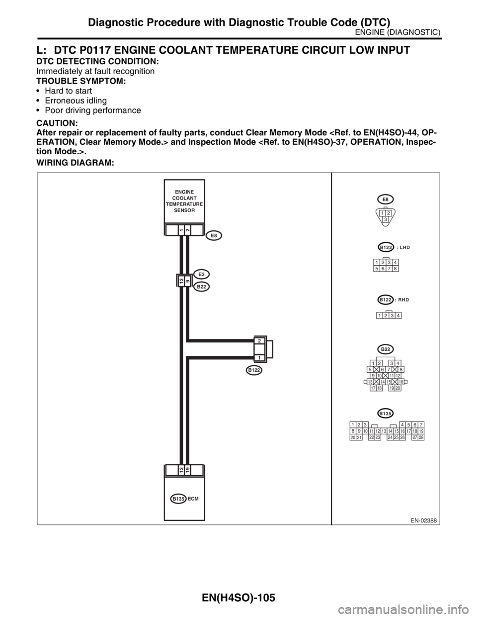
L: DTC P0117 ENGINE COOLANT TEMPERATURE CIRCUIT LOW INPUT
DTC DETECTING CONDITION:
Immediately at fault recognition
TROUBLE SYMPTOM:
Hard to start
Erroneous idling
Poor driving performance
CAUTION:
After repair or replacement of faulty parts, conduct Clear Memory Mode
WIRING DIAGRAM:
EN-02388
1
2
B122
1912
913
B135ECM
21
E3
B22
E8 ENGINE
COOLANT
TEMPERATURE
SENSOR
E8
12
3
B135
567
82 1
94
310
24 22 23 251112131415
26 27
281617181920 21
B22
125678
131415169101112
34
17181920
B122 : LHD
12345678
B122 : RHD
1234
Page 1204 of 2870

EN(H4SO)-106
ENGINE (DIAGNOSTIC)
Diagnostic Procedure with Diagnostic Trouble Code (DTC)
Step Check Yes No
1 CHECK CURRENT DATA.
1) Start the engine.
2) Read the data of engine coolant tempera-
ture sensor signal using Subaru Select Monitor
or the OBD-II general scan tool.
N
OTE:
Subaru Select Monitor
For detailed operation procedure, refer to the
“READ CURRENT DATA FOR ENGINE”.
OBD-II general scan tool
For detailed operation procedures, refer to the
OBD-II Scan Tool Instruction Manual.Is engine coolant temperature
more than 150°C (302°F)?Go to step 2.Repair the poor
contact.
N
OTE:
In this case repair
the following:
Poor contact in
engine coolant
temperature sen-
sor
Poor contact in
ECM
Poor contact in
coupling connector
Poor contact in
joint connector
2 CHECK HARNESS BETWEEN ENGINE
COOLANT TEMPERATURE SENSOR AND
ECM CONNECTOR.
1) Turn the ignition switch to OFF.
2) Disconnect the connectors from the engine
coolant temperature sensor.
3) Turn the ignition switch to ON.
4) Read the data of engine coolant tempera-
ture sensor signal using Subaru Select Monitor
or the OBD-II general scan tool.
NOTE:
Subaru Select Monitor
For detailed operation procedure, refer to the
“READ CURRENT DATA FOR ENGINE”.
OBD-II general scan tool
For detailed operation procedures, refer to the
OBD-II Scan Tool Instruction Manual.Is engine coolant temperature
less than −40°C (−40°F)?Replace the
engine coolant
temperature sen-
sor.
Engine Coolant
Temperature Sen-
sor.>Repair ground
short circuit in har-
ness between
engine coolant
temperature sen-
sor and ECM con-
nector.
Page 1205 of 2870

EN(H4SO)-107
ENGINE (DIAGNOSTIC)
Diagnostic Procedure with Diagnostic Trouble Code (DTC)
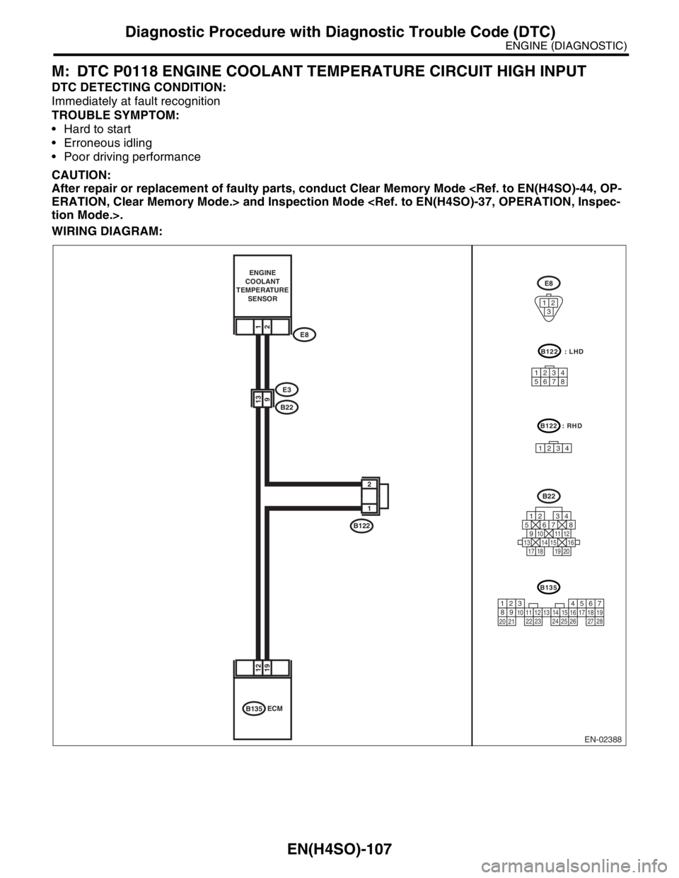
M: DTC P0118 ENGINE COOLANT TEMPERATURE CIRCUIT HIGH INPUT
DTC DETECTING CONDITION:
Immediately at fault recognition
TROUBLE SYMPTOM:
Hard to start
Erroneous idling
Poor driving performance
CAUTION:
After repair or replacement of faulty parts, conduct Clear Memory Mode
WIRING DIAGRAM:
EN-02388
1
2
B122
1912
913
B135ECM
21
E3
B22
E8 ENGINE
COOLANT
TEMPERATURE
SENSOR
E8
12
3
B135
567
82 1
94
310
24 22 23 251112131415
26 27
281617181920 21
B22
125678
131415169101112
34
17181920
B122 : LHD
12345678
B122 : RHD
1234