2004 SUBARU FORESTER ignition
[x] Cancel search: ignitionPage 1488 of 2870

ME(H4DOTC)-32
MECHANICAL
Idle Speed
3. Idle Speed
A: INSPECTION
1. USING SUBARU SELECT MONITOR
1) Before checking the idle speed, check the fol-
lowing:
(1) Ensure the air cleaner element is free from
clogging, ignition timing is correct, spark plugs
are in good condition, and that the hoses are
connected properly.
(2) Ensure the malfunction indicator light does
not illuminate.
2) Warm-up the engine.
3) Stop the engine, and then turn the ignition switch
to OFF.
4) Insert the cartridge to Subaru Select Monitor.
5) Connect the Subaru Select Monitor to data link
connector.
6) Turn the ignition switch to ON, and Subaru Se-
lect Monitor switch to ON.
7) Select the {2. Each System Check} in Main
Menu.
8) Select the {Engine Control System} in Selection
Menu.
9) Select the {1. Current Data Display & Save} in
Engine Control System Diagnosis.
10) Select the {1.12 Data Display} in Data Display
Menu.
11) Start the engine, and then read the engine idle
speed.
12) Check the idle speed when unloaded. (With
headlights, heater fan, rear defroster, radiator fan,
air conditioning, etc. OFF)
Idle speed [No load and gears in neutral]:
700
±100 rpm
13) Check the idle speed when loaded. (Turn the
air conditioning switch to “ON” and operate the
compressor for at least 1 minute before measure-
ment.)
Idle speed [A/C “ON”, no load and gears in neu-
tral]:
A/C Refrigerant pressure (LOW)
MT: 725
±100 rpm
AT: 750
±100 rpm
A/C Refrigerant pressure (HIGH)
MT: 800
±100 rpm
AT: 825
±100 rpm
NOTE:
As idle speed is controlled by the automatic adjust-
ment type, it can not be adjusted manually. If the
idle speed is out of specifications, refer to General
On-board Diagnosis Table under “Engine Control
System”.
Page 1489 of 2870

ME(H4DOTC)-33
MECHANICAL
Ignition Timing
4. Ignition Timing
A: INSPECTION
1. USING SUBARU SELECT MONITOR
1) Before checking the ignition timing speed, check
the following:
(1) Ensure the air cleaner element is free from
clogging, spark plugs are in good condition, and
that hoses are connected properly.
(2) Ensure the malfunction indicator light does
not illuminate.
2) Warm-up the engine.
3) Stop the engine, and then turn the ignition switch
to OFF.
4) Insert the cartridge to Subaru Select Monitor.
5) Connect the Subaru Select Monitor to data link
connector.
6) Turn the ignition switch to ON, and Subaru Se-
lect Monitor switch to ON.
7) Select the {2. Each System Check} in Main
Menu.
8) Select the {Engine Control System} in Selection
Menu.
9) Select the {1. Current Data Display & Save} in
Engine Control System Diagnosis.
10) Select the {1.12 Data Display} in Data Display
Menu.
11) Start the engine and check the ignition timing at
idle speed.
Ignition timing [BTDC/rpm]:
2.0 L model
12
°±10°/700
2.5 L model
17
°±10°/700
If the timing is not correct, check the ignition control
system. Refer to Engine Control System.
Page 1490 of 2870
ME(H4DOTC)-34
MECHANICAL
Intake Manifold Vacuum
5. Intake Manifold Vacuum
A: INSPECTION
1) Warm-up the engine.
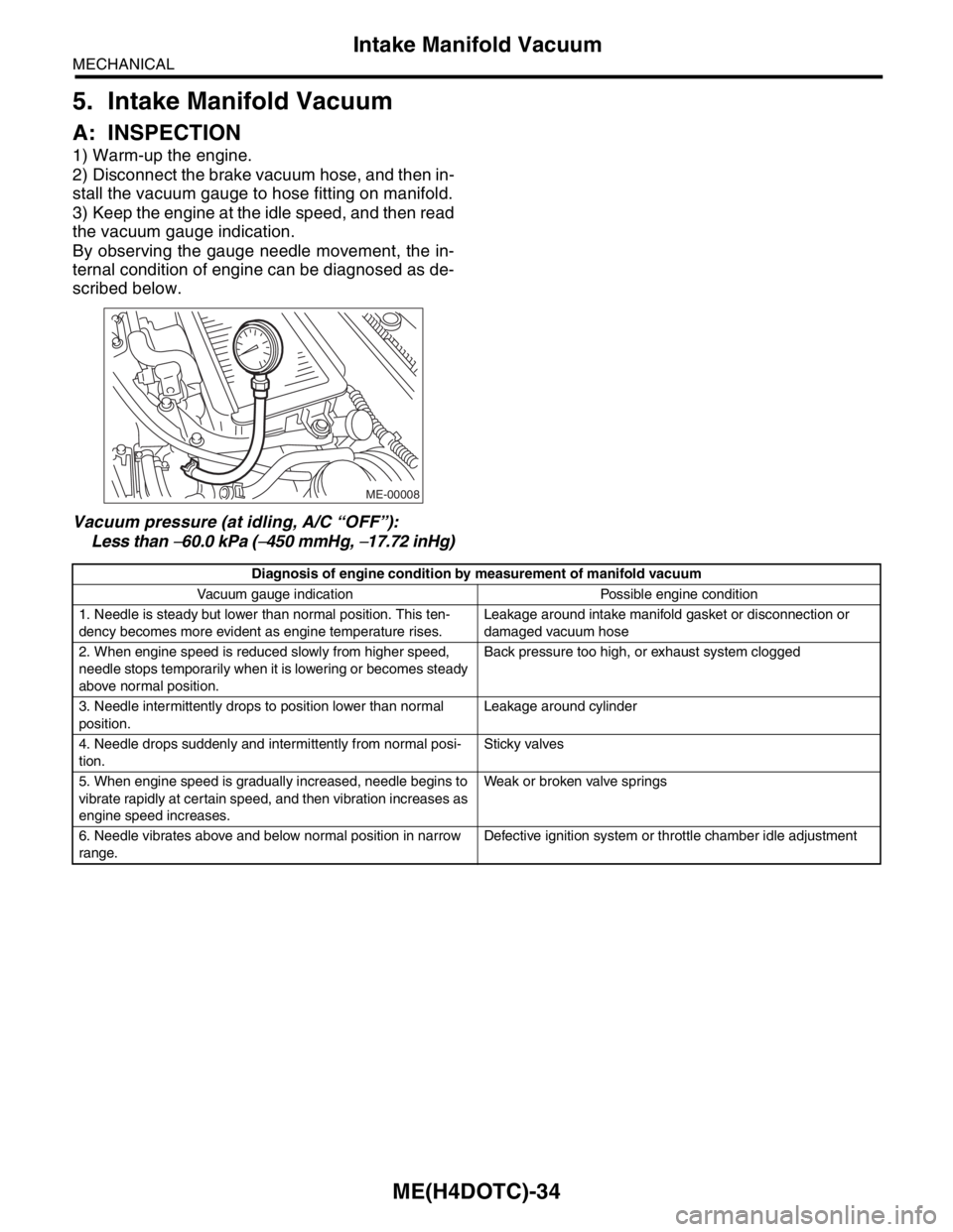
2) Disconnect the brake vacuum hose, and then in-
stall the vacuum gauge to hose fitting on manifold.
3) Keep the engine at the idle speed, and then read
the vacuum gauge indication.
By observing the gauge needle movement, the in-
ternal condition of engine can be diagnosed as de-
scribed below.
Vacuum pressure (at idling, A/C “OFF”):
Less than
−60.0 kPa (−450 mmHg, −17.72 inHg)
ME-00008
Diagnosis of engine condition by measurement of manifold vacuum
Vacuum gauge indication Possible engine condition
1. Needle is steady but lower than normal position. This ten-
dency becomes more evident as engine temperature rises.Leakage around intake manifold gasket or disconnection or
damaged vacuum hose
2. When engine speed is reduced slowly from higher speed,
needle stops temporarily when it is lowering or becomes steady
above normal position.Back pressure too high, or exhaust system clogged
3. Needle intermittently drops to position lower than normal
position.Leakage around cylinder
4. Needle drops suddenly and intermittently from normal posi-
tion.Sticky valves
5. When engine speed is gradually increased, needle begins to
vibrate rapidly at certain speed, and then vibration increases as
engine speed increases.Weak or broken valve springs
6. Needle vibrates above and below normal position in narrow
range.Defective ignition system or throttle chamber idle adjustment
Page 1493 of 2870
ME(H4DOTC)-37
MECHANICAL
Valve Clearance
8. Valve Clearance
A: INSPECTION
Inspection and adjustment of the valve clearance
should be performed while engine is cold.
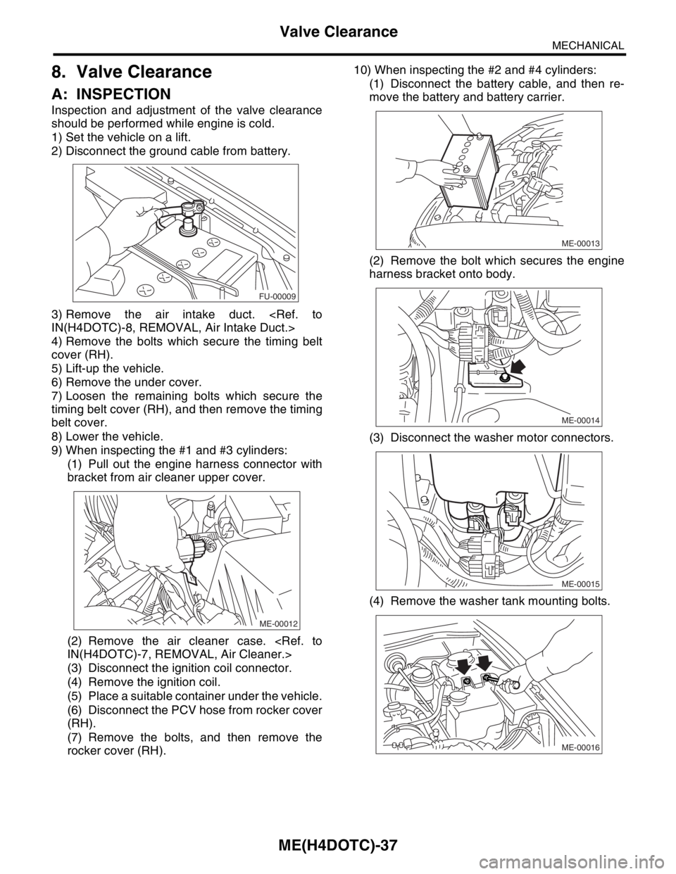
1) Set the vehicle on a lift.
2) Disconnect the ground cable from battery.
3) Remove the air intake duct.
4) Remove the bolts which secure the timing belt
cover (RH).
5) Lift-up the vehicle.
6) Remove the under cover.
7) Loosen the remaining bolts which secure the
timing belt cover (RH), and then remove the timing
belt cover.
8) Lower the vehicle.
9) When inspecting the #1 and #3 cylinders:
(1) Pull out the engine harness connector with
bracket from air cleaner upper cover.
(2) Remove the air cleaner case.
(3) Disconnect the ignition coil connector.
(4) Remove the ignition coil.
(5) Place a suitable container under the vehicle.
(6) Disconnect the PCV hose from rocker cover
(RH).
(7) Remove the bolts, and then remove the
rocker cover (RH).10) When inspecting the #2 and #4 cylinders:
(1) Disconnect the battery cable, and then re-
move the battery and battery carrier.
(2) Remove the bolt which secures the engine
harness bracket onto body.
(3) Disconnect the washer motor connectors.
(4) Remove the washer tank mounting bolts.
FU-00009
ME-00012
ME-00013
ME-00014
ME-00015
ME-00016
Page 1494 of 2870
ME(H4DOTC)-38
MECHANICAL
Valve Clearance
(5) Move the washer tank upward.
(6) Disconnect the ignition coil connector.
(7) Remove the ignition coil.
(8) Place a suitable container under the vehicle.
(9) Disconnect the PCV hose from rocker cover
(LH).
(10)Remove the bolts, and then remove the
rocker cover (LH).
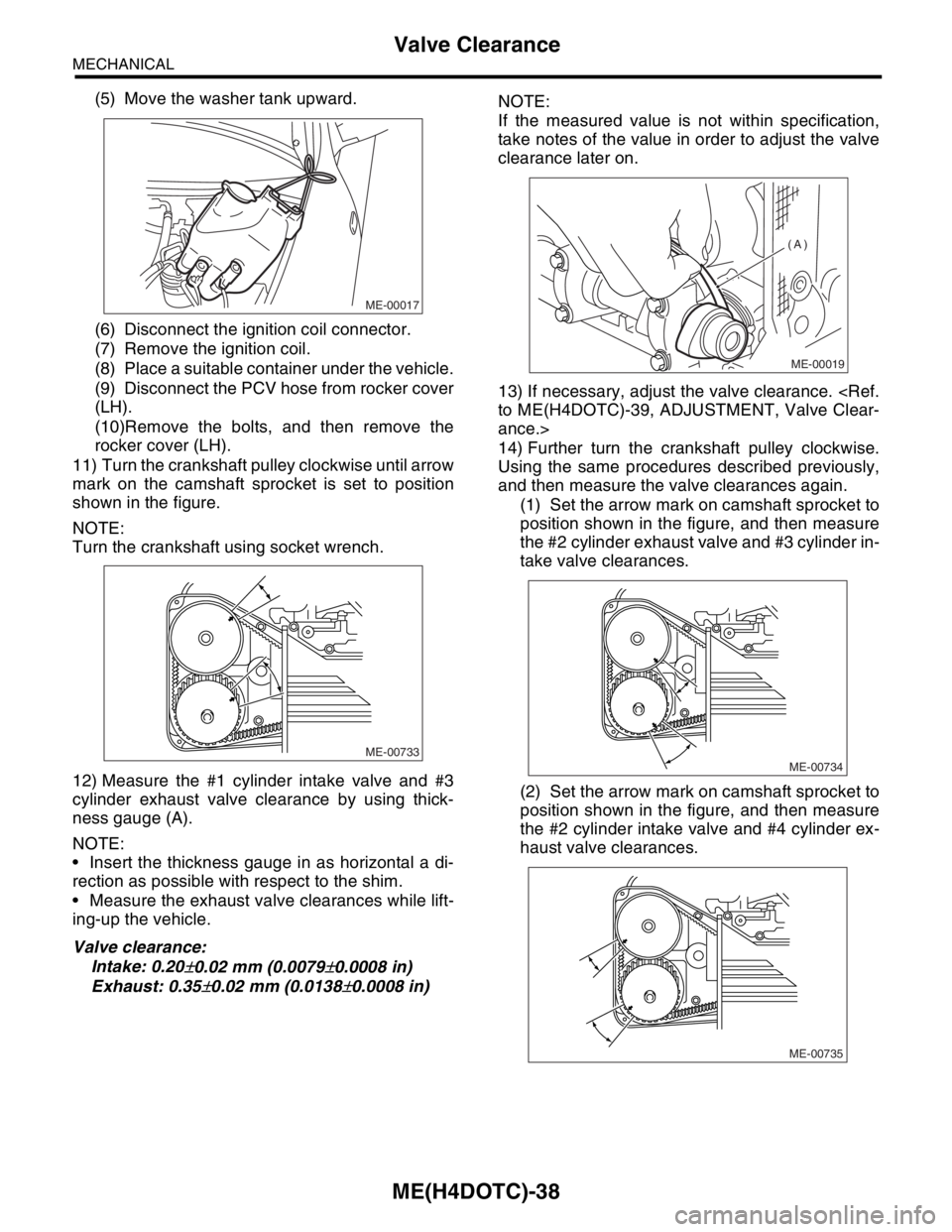
11) Turn the crankshaft pulley clockwise until arrow
mark on the camshaft sprocket is set to position
shown in the figure.
NOTE:
Turn the crankshaft using socket wrench.
12) Measure the #1 cylinder intake valve and #3
cylinder exhaust valve clearance by using thick-
ness gauge (A).
NOTE:
Insert the thickness gauge in as horizontal a di-
rection as possible with respect to the shim.
Measure the exhaust valve clearances while lift-
ing-up the vehicle.
Valve clearance:
Intake: 0.20
±0.02 mm (0.0079±0.0008 in)
Exhaust: 0.35
±0.02 mm (0.0138±0.0008 in)NOTE:
If the measured value is not within specification,
take notes of the value in order to adjust the valve
clearance later on.
13) If necessary, adjust the valve clearance.
ance.>
14) Further turn the crankshaft pulley clockwise.
Using the same procedures described previously,
and then measure the valve clearances again.
(1) Set the arrow mark on camshaft sprocket to
position shown in the figure, and then measure
the #2 cylinder exhaust valve and #3 cylinder in-
take valve clearances.
(2) Set the arrow mark on camshaft sprocket to
position shown in the figure, and then measure
the #2 cylinder intake valve and #4 cylinder ex-
haust valve clearances.
ME-00017
ME-00733
ME-00019
(A)
ME-00734
ME-00735
Page 1497 of 2870
FUJI HEAVY INDUSTRIES LTD. G8080GE3
2004 FORESTER SERVICE MANUAL QUICK REFERENCE INDEX
ENGINE SECTION 2
This service manual has been prepared
to provide SUBARU service personnel
with the necessary information and data
for the correct maintenance and repair
of SUBARU vehicles.
This manual includes the procedures
for maintenance, disassembling, reas-
sembling, inspection and adjustment of
components and diagnostics for guid-
ance of experienced mechanics.
Please peruse and utilize this manual
fully to ensure complete repair work for
satisfying our customers by keeping
their vehicle in optimum condition.
When replacement of parts during
repair work is needed, be sure to use
SUBARU genuine parts.
All information, illustration and specifi-
cations contained in this manual are
based on the latest product information
available at the time of publication
approval.FUEL INJECTION (FUEL SYSTEM) FU(H4DOTC)
EMISSION CONTROL
(AUX. EMISSION CONTROL DEVICE)EC(H4DOTC)
INTAKE (INDUCTION) IN(H4DOTC)
MECHANICAL ME(H4DOTC)
EXHAUST EX(H4DOTC)
COOLING CO(H4DOTC)
LUBRICATION LU(H4DOTC)
SPEED CONTROL SYSTEM SP(H4DOTC)
IGNITION IG(H4DOTC)
STARTING/CHARGING SYSTEM SC(H4DOTC)
ENGINE (DIAGNOSTIC) EN(H4DOTC)
Page 1498 of 2870

MECHANICAL
ME(H4DOTC)
Page
1. General Description ....................................................................................2
2. Compression .............................................................................................31
3. Idle Speed .................................................................................................32
4. Ignition Timing ...........................................................................................33
5. Intake Manifold Vacuum............................................................................34
6. Engine Oil Pressure ..................................................................................35
7. Fuel Pressure ............................................................................................36
8. Valve Clearance ........................................................................................37
9. Engine Assembly ......................................................................................41
10. Engine Mounting .......................................................................................50
11. Preparation for Overhaul ...........................................................................51
12. V-belt .........................................................................................................52
13. Crank Pulley ..............................................................................................55
14. Timing Belt Cover......................................................................................57
15. Timing Belt Assembly................................................................................58
16. Cam Sprocket ...........................................................................................67
17. Crank Sprocket .........................................................................................68
18. Camshaft ...................................................................................................69
19. Cylinder Head Assembly ...........................................................................76
20. Cylinder Block ...........................................................................................84
21. Intake and Exhaust Valve .......................................................................115
22. Piston ......................................................................................................116
23. Connecting Rod ......................................................................................117
24. Crankshaft ...............................................................................................118
25. Engine Trouble in General ......................................................................119
26. Engine Noise ...........................................................................................124
Page 1499 of 2870
ME(H4DOTC)-41
MECHANICAL
Engine Assembly
9. Engine Assembly
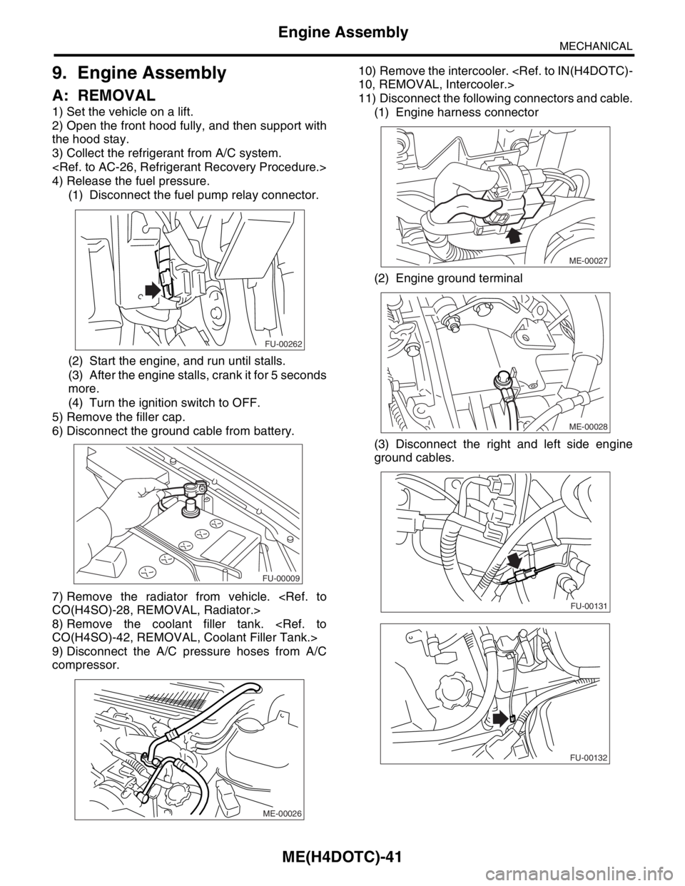
A: REMOVAL
1) Set the vehicle on a lift.
2) Open the front hood fully, and then support with
the hood stay.
3) Collect the refrigerant from A/C system.
4) Release the fuel pressure.
(1) Disconnect the fuel pump relay connector.
(2) Start the engine, and run until stalls.
(3) After the engine stalls, crank it for 5 seconds
more.
(4) Turn the ignition switch to OFF.
5) Remove the filler cap.
6) Disconnect the ground cable from battery.
7) Remove the radiator from vehicle.
8) Remove the coolant filler tank.
9) Disconnect the A/C pressure hoses from A/C
compressor.10) Remove the intercooler.
11) Disconnect the following connectors and cable.
(1) Engine harness connector
(2) Engine ground terminal
(3) Disconnect the right and left side engine
ground cables.
FU-00262
FU-00009
ME-00026
ME-00027
ME-00028
FU-00131
FU-00132