Page 1624 of 2870
IG(H4DOTC)-8
IGNITION
Ignition Coil & Ignitor ASSY
3. Ignition Coil & Ignitor ASSY
A: REMOVAL
Direct ignition type has been adopted. Refer to the
“SparkPlug Removal” for removal procedure.
to IG(H4DOTC)-5, REMOVAL, Spark Plug.>
B: INSTALLATION
Install in the reverse order of removal.
Tightening torque:
16 N
⋅m (1.6 kgf-m, 11.7 ft-lb)
C: INSPECTION
Ignitor is integrated with the coil. Therefore resis-
tance cannot be measured.
Page 1625 of 2870

FUJI HEAVY INDUSTRIES LTD. G8080GE3
2004 FORESTER SERVICE MANUAL QUICK REFERENCE INDEX
ENGINE SECTION 2
This service manual has been prepared
to provide SUBARU service personnel
with the necessary information and data
for the correct maintenance and repair
of SUBARU vehicles.
This manual includes the procedures
for maintenance, disassembling, reas-
sembling, inspection and adjustment of
components and diagnostics for guid-
ance of experienced mechanics.
Please peruse and utilize this manual
fully to ensure complete repair work for
satisfying our customers by keeping
their vehicle in optimum condition.
When replacement of parts during
repair work is needed, be sure to use
SUBARU genuine parts.
All information, illustration and specifi-
cations contained in this manual are
based on the latest product information
available at the time of publication
approval.FUEL INJECTION (FUEL SYSTEM) FU(H4DOTC)
EMISSION CONTROL
(AUX. EMISSION CONTROL DEVICE)EC(H4DOTC)
INTAKE (INDUCTION) IN(H4DOTC)
MECHANICAL ME(H4DOTC)
EXHAUST EX(H4DOTC)
COOLING CO(H4DOTC)
LUBRICATION LU(H4DOTC)
SPEED CONTROL SYSTEM SP(H4DOTC)
IGNITION IG(H4DOTC)
STARTING/CHARGING SYSTEM SC(H4DOTC)
ENGINE (DIAGNOSTIC) EN(H4DOTC)
Page 1629 of 2870

FUJI HEAVY INDUSTRIES LTD. G8080GE3
2004 FORESTER SERVICE MANUAL QUICK REFERENCE INDEX
ENGINE SECTION 2
This service manual has been prepared
to provide SUBARU service personnel
with the necessary information and data
for the correct maintenance and repair
of SUBARU vehicles.
This manual includes the procedures
for maintenance, disassembling, reas-
sembling, inspection and adjustment of
components and diagnostics for guid-
ance of experienced mechanics.
Please peruse and utilize this manual
fully to ensure complete repair work for
satisfying our customers by keeping
their vehicle in optimum condition.
When replacement of parts during
repair work is needed, be sure to use
SUBARU genuine parts.
All information, illustration and specifi-
cations contained in this manual are
based on the latest product information
available at the time of publication
approval.FUEL INJECTION (FUEL SYSTEM) FU(H4DOTC)
EMISSION CONTROL
(AUX. EMISSION CONTROL DEVICE)EC(H4DOTC)
INTAKE (INDUCTION) IN(H4DOTC)
MECHANICAL ME(H4DOTC)
EXHAUST EX(H4DOTC)
COOLING CO(H4DOTC)
LUBRICATION LU(H4DOTC)
SPEED CONTROL SYSTEM SP(H4DOTC)
IGNITION IG(H4DOTC)
STARTING/CHARGING SYSTEM SC(H4DOTC)
ENGINE (DIAGNOSTIC) EN(H4DOTC)
Page 1632 of 2870

EN(H4DOTC)-2
ENGINE (DIAGNOSTIC)
Basic Diagnostics Procedure
1. Basic Diagnostics Procedure
A: PROCEDURE
1. ENGINE
Step Check Yes No
1 CHECK ENGINE START FAILURE.
1) Ask the customer when and how the trou-
ble occurred using the interview check list.
Check List for Interview.>
2) Start the engine.Does the engine start? Go to step 2.Inspection using
“Diagnostics for
Engine Start Fail-
ure”.
EN(H4DOTC)-59,
Diagnostics for
Engine Starting
Fai lu r e.>
2 CHECK ILLUMINATION OF MALFUNCTION
INDICATOR LIGHT.Does malfunction indicator
light illuminate?Go to step 3.Inspection using
“General Diagnos-
tic Table”.
EN(H4DOTC)-
295, General Diag-
nostic Table.>
3 CHECK INDICATION OF DTC ON DISPLAY.
1) Turn the ignition switch to OFF.
2) Connect the Subaru Select Monitor or the
OBD-II general scan tool to data link connec-
tor.
3) Turn the ignition switch to ON and the Sub-
aru Select Monitor or OBD-II general scan tool
switch to ON.
4) Read the DTC on the Subaru Select Moni-
tor or OBD-II general scan tool.Does the Subaru Select Moni-
tor or OBD-II general scan tool
indicate DTC?Record the
DTC.Repair the
trouble cause.
EN(H4DOTC)-74,
List of Diagnostic
Trouble Code
(DTC).> Go to
step 4.Repair the related
parts.
N
OTE:
If DTC is not shown
on display although
the malfunction in-
dicator light illumi-
nates, perform the
diagnostics for mal-
function indicator
light circuit or com-
bination meter.
EN(H4DOTC)-50,
Malfunction Indica-
tor Light.>
4 PERFORM THE DIAGNOSIS.
1) Perform clear memory mode.
EN(H4DOTC)-47, Clear Memory Mode.>
2) Perform the “INSPECTION MODE”.
to EN(H4DOTC)-40, Inspection Mode.>Does the Subaru Select Moni-
tor or OBD-II general scan tool
indicate DTC?Check on “Diag-
nostic Chart with
Diagnostic Trou-
ble Code (DTC)”
EN(H4DOTC)-80,
Diagnostic Proce-
dure with Diagnos-
tic Trouble Code
(DTC).>Finish the diagno-
sis.
Page 1646 of 2870
EN(H4DOTC)-16
ENGINE (DIAGNOSTIC)
Electrical Component Location
SOLENOID VALVE, ACTUATOR, EMISSION CONTROL SYSTEM PARTS AND IGNITION SYSTEM
PARTS
(1) Wastegate control solenoid valve (4) Ignition coil (7) Injector
(2) Idle air control solenoid valve (5) Tumble generator valve actuator
(3) Purge control solenoid valve (6) Oil frow control solenoid valve
EN-02406
(2)
(5)(4) (1)
(5)
(3)
(6)
(7)
(7) (6)
Page 1653 of 2870

EN(H4DOTC)-23
ENGINE (DIAGNOSTIC)
Engine Control Module (ECM) I/O Signal
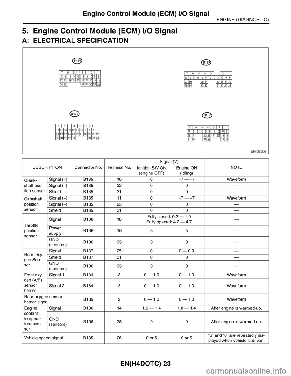
5. Engine Control Module (ECM) I/O Signal
A: ELECTRICAL SPECIFICATION
DESCRIPTION Connector No. Terminal No.Signal (V)
NOTE
Ignition SW ON
(engine OFF)Engine ON
(Idling)
Crank-
shaft posi-
tion sensorSignal (+) B135 10 0−7 — +7 Waveform
Signal (−) B135 22 0 0 —
Shield B135 31 0 0 —
Camshaft
position
sensorSignal (+) B135 11 0−7 — +7 Waveform
Signal (−) B135 23 0 0 —
Shield B135 31 0 0 —
Throttle
position
sensorSignal B136 18Fully closed: 0.2 — 1.0
Fully opened: 4.2 — 4.7—
Pow er
supplyB136 16 5 5 —
GND
(sensors)B136 35 0 0 —
Rear Oxy-
gen Sen-
sorSignal B137 25 0 0 — 0.9 —
Shield B137 31 0 0 —
GND
(sensors)B136 35 0 0 —
Fr o nt ox y-
gen (A/F)
sensor
heaterSignal 1 B134 3 0 — 1.0 0 — 1.0 Waveform
Signal 2 B134 2 0 — 1.0 0 — 1.0 Waveform
Rear oxygen sensor
heater signalB135 2 0 — 1.0 0 — 1.0 Waveform
Engine
coolant
tempera-
ture sen-
sorSignal B136 14 1.0 — 1.4 1.0 — 1.4 After engine is warmed-up.
GND
(sensors)B136 35 0 0 After engine is warmed-up.
Vehicle speed signal B135 26 0 or 5 0 or 5“5” and “0” are repeatedly dis-
played when vehicle is driven.
EN-02308
B134
34
3330 31 3229 26
27
28 25
1
2
8 9 310
11 12
19 20 21 13 14
15
16 17
18 22 23 24
3330 31 32
29 26
27
28 25
7
8 9 5 64
10
11 12
19 20 21 13 14
15 16
17
18 22
23 241
2 3
7 5 64
3534
B137 B135
B136
33
30 31
32
29 26
27
28 25
8 910
11 12
19
20 21 13 14
15 16 17
18
22
23 241
2
3
75 64
3534
30 3129
26
27
28 25
8 910
11 12
19 20 21 13 14
15 16 17
18 22
23 241 2
3
75 64
Page 1654 of 2870

EN(H4DOTC)-24
ENGINE (DIAGNOSTIC)
Engine Control Module (ECM) I/O Signal
AV C S
camshaft
position
sensor RHSignal (+) B135 21 0−7 — +7 Waveform
Signal (−) B135 29 0 0 —
Shield B135 30 0 0 —
AV C S
camshaft
position
sensor LHSignal (+) B135 20 0−7 — +7 Waveform
Signal (−) B135 28 0 0 —
Shield B135 30 0 0 —
Generator signal B134 22ON: 1, or less
OFF: 10 — 13ON: 1, or less
OFF: 10 — 13Wavefor m
Air flow
sensorSignal B136 23 — 0.3 — 4.5 —
Shield B136 32 0 0 —
GND B136 31 0 0 —
Intake air temperature
sensor signalB136 13 0.3 — 4.6 0.3 — 4.6 —
Exhaust
gas tem-
perature
sensorSignal B136 24 — — —
GND
(sensor)B136 35 0 0 —
Tu m b l e
generator
valve posi-
tion sen-
sor RHSignal B136 27Fully closed: 3.8 — 4.9
Fully opened: 0.2 — 0.9—
Pow er
supplyB136 16 5 5 —
GND
(sensor)B136 35 0 0 —
Tu m b l e
generator
valve posi-
tion sen-
sor LHSignal B136 26Fully closed: 3.8 — 4.9
Fully opened: 0.2 — 0.9—
Pow er
supplyB136 16 5 5 —
GND
(sensor)B136 35 0 0 —
Tumble generator valve
RH (open)B134 9 0 or 10 — 13 0 or 13 — 14 Waveform
Tumble generator valve
RH (close)B134 8 0 or 10 — 13 0 or 13 — 14 Waveform
Tumble generator valve
LH (open)B134 11 0 or 10 — 13 0 or 13 — 14 Waveform
Tumble generator valve
LH (close)B134 10 0 or 10 — 13 0 or 13 — 14 Waveform
Wastegate control sole-
noid valveB134 32 0 or 10 — 13 0 or 13 — 14 —
Starter switch B137 8 0 0 Cranking: 8 — 14
A/C switch B137 17ON: 10 — 13
OFF: 0ON: 13 — 14
OFF: 0—
Ignition switch B137 14 10 — 13 13 — 14 —
Neutral Position Switch B137 9ON: 12±0.5
OFF: 0Switch is ON when gear is in
neutral position.
Test Mode Connector B137 15 10 — 13 13 — 14 When connected: 0
Knock
sensorSignal B136 25 2.8 2.8 —
Shield B136 33 0 0 —
Back-up power supply B135 19 10 — 13 13 — 14 Ignition switch “OFF”: 10 — 13
Control module power
supplyB135 5 10 — 13 13 — 14 —
B135 6 10 — 13 13 — 14 — DESCRIPTION Connector No. Terminal No.Signal (V)
NOTE
Ignition SW ON
(engine OFF)Engine ON
(Idling)
Page 1655 of 2870

EN(H4DOTC)-25
ENGINE (DIAGNOSTIC)
Engine Control Module (ECM) I/O Signal
Sensor power supply B136 16 5 5 —
Oil flow
control
solenoid
valve RHSignal (+) B134 18ON: 10 — 13
OFF: 0ON: 13 — 14
OFF: 0—
Signal (−) B134 28 0 0 —
Oil flow
control
solenoid
valve LHSignal (+) B134 19ON: 10 — 13
OFF: 0ON: 13 — 14
OFF: 0—
Signal (−) B134 29 0 0 —
Ignition
control#1 B135 18 0 13 — 14 Waveform
#2 B135 17 0 13 — 14 Waveform
#3 B135 16 0 13 — 14 Waveform
#4 B135 15 0 13 — 14 Waveform
Fuel injec-
tor#1 B136 6 10 — 13 1 — 14 Waveform
#2 B136 5 10 — 13 1 — 14 Waveform
#3 B136 4 10 — 13 1 — 14 Waveform
#4 B136 3 10 — 13 1 — 14 Waveform
Idle air
control
solenoid
valveSignal B134 27 0 or 13 — 14 0 or 13 — 14 Waveform
Fuel pump
control unitDiagnosis
signalB137 28 10 — 13 13 — 14 Waveform
Control
signalB135 27 0 or 5 0 or 5 —
A/C relay control B135 33ON: 0.5, or less
OFF: 10 — 13ON: 0.5, or less
OFF: 13 — 14—
Radiator fan relay 1 con-
trolB135 25ON: 0.5, or less
OFF: 10 — 13ON: 0.5, or less
OFF: 13 — 14—
Radiator fan relay 2 con-
trolB135 24ON: 0.5, or less
OFF: 10 — 13ON: 0.5, or less
OFF: 13 — 14Model with A/C
Malfunction indicator
lightB134 17 — —Light “ON”: 1, or less
Light “OFF”: 10 — 14
Engine speed output B134 23 — 0 — 13, or more Waveform
Purge control solenoid
valveB134 14ON: 1, or less
OFF: 10 — 13ON: 1, or less
OFF: 13 — 14Wavefor m
Manifold
absolute
pressure
sensorSignal B136 22 1.7 — 2.4 1.1 — 1.6
— Pow er
supplyB136 16 5 5
GND
(sensors)B136 35 0 0
Fuel level sensor B136 20 0.12 — 4.75 0.12 — 4.75 —
Small light switch B137 12ON: 0
OFF: 10 — 13ON: 0
OFF: 13 — 14—
Blower fan switch B137 13ON: 0
OFF: 10 — 13ON: 0
OFF: 13 — 14—
Rear defogger switch B137 11ON: 0
OFF: 10 — 13ON: 0
OFF: 13 — 14—
Power steering oil pres-
sure switchB137 10 10 — 13ON: 0
OFF: 13 — 14—
Wiper switch B137 23ON: 10 — 13
OFF: 0ON: 13 — 14
OFF: 0— DESCRIPTION Connector No. Terminal No.Signal (V)
NOTE
Ignition SW ON
(engine OFF)Engine ON
(Idling)