2004 SUBARU FORESTER ignition
[x] Cancel search: ignitionPage 1696 of 2870

EN(H4DOTC)-66
ENGINE (DIAGNOSTIC)
Diagnostics for Engine Starting Failure
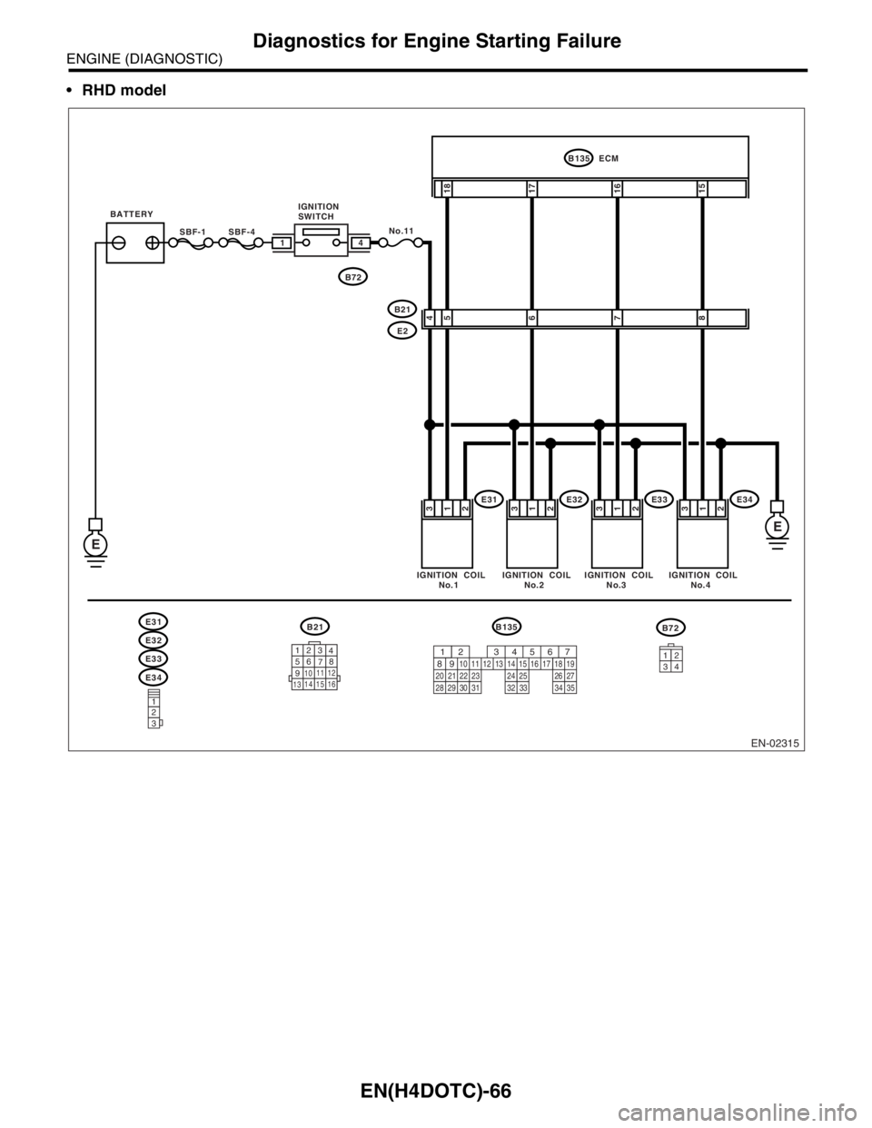
RHD model
EN-02315
SBF-4SBF-1
B135
18
17
16
15
ECM
No.11
E
E
41
E31
E31
E32
E33
E34IGNITION COIL
No.1IGNITION COIL
No.2IGNITION COIL
No.3IGNITION COIL
No.4
E32E33E34
123
123
4
56
78
9
1011 12
1314 15 16
B21B135B72
34
12
5 4
6
7
8
3
1
23
1
23
1
23
1
2
B21
E2 IGNITION
SWITCH
B72
567
82 1
94 310
24 22 23 2511 12 13 14 15
26 27
2816 17 18 19
20 21
29 30 31 32 33 34 35
BATTERY
Page 1697 of 2870

EN(H4DOTC)-67
ENGINE (DIAGNOSTIC)
Diagnostics for Engine Starting Failure
Step Check Yes No
1 CHECK SPARK PLUG CONDITION.
1) Remove the spark plug.
2) Check the spark plug condition.
plug.
2 CHECK IGNITION SYSTEM FOR SPARKS.
1) Connect the spark plug to ignition coil.
2) Release the fuel pressure.
PRESSURE, OPERATION, Fuel.>
3) Contact the spark plug’s thread portion on
engine.
4) While opening the throttle valve fully, crank
the engine to check that spark occurs at each
cylinder.Does spark occur at each cyl-
inder?Check fuel pump
system.
FUEL PUMP CIR-
CUIT, Diagnostics
for Engine Start-
ing Failure.>Go to step 3.
3 CHECK POWER SUPPLY CIRCUIT FOR IG-
NITION COIL & IGNITOR ASSY.
1) Turn the ignition switch to OFF.
2) Disconnect the connector from ignition coil
& ignitor ASSY.
3) Turn the ignition switch to ON.
4) Measure the power supply voltage between
ignition coil & ignitor ASSY connector and
engine ground.
Connector & terminal
(E31) No. 3 (+) — Engine ground (
−):
(E32) No. 3 (+) — Engine ground (
−):
(E33) No. 3 (+) — Engine ground (
−):
(E34) No. 3 (+) — Engine ground (
−):Is the voltage more than 10 V? Go to step 4.Repair the har-
ness and connec-
tor.
N
OTE:
In this case repair
the following:
Open circuit in
harness between
ignition coil & igni-
tor ASSY, and igni-
tion switch
connector
Poor contact in
coupling connector
4 CHECK HARNESS OF IGNITION COIL & IG-
NITOR ASSY GROUND CIRCUIT.
1) Turn the ignition switch to OFF.
2) Measure the resistance between ignition
coil & ignitor ASSY connector and engine
ground.
Connector & terminal
(E31) No. 2 — Engine ground:
(E32) No. 2 — Engine ground:
(E33) No. 2 — Engine ground:
(E34) No. 2 — Engine ground:Is the resistance less than 5
Ω?Go to step 5.Repair the har-
ness and connec-
tor.
NOTE:
In this case repair
the following:
Open circuit in
harness between
ignition coil & igni-
tor ASSY connec-
tor and engine
ground terminal
5 CHECK HARNESS BETWEEN ECM AND IG-
NITION COIL & IGNITOR ASSY CONNEC-
TOR.
1) Turn the ignition switch to OFF.
2) Disconnect the connector from ECM.
3) Disconnect the connector from ignition coil
& ignitor ASSY.
4) Measure the resistance of harness
between ECM and ignition coil & ignitor ASSY
connector.
Connector & terminal
(B135) No. 15 — (E34) No. 1:
(B135) No. 16 — (E33) No. 1:
(B135) No. 17 — (E32) No. 1:
(B135) No. 18 — (E31) No. 1:Is the resistance less than 1
Ω?Go to step 6.Repair the har-
ness and connec-
tor.
N
OTE:
In this case repair
the following:
OPEN CIR-
CUIT IN HAR-
NESS BETWEEN
ECM AND IGNI-
TION COIL &
IGNITOR ASSY
CONNECTOR.
Poor contact in
coupling connector
Page 1698 of 2870

EN(H4DOTC)-68
ENGINE (DIAGNOSTIC)
Diagnostics for Engine Starting Failure
6 CHECK HARNESS BETWEEN ECM AND IG-
NITION COIL & IGNITOR ASSY CONNEC-
TOR.
Measure the resistance of harness between
ECM and engine ground.
Connector & terminal:
(B135) No. 15 — Engine ground:
(B135) No. 16 — Engine ground:
(B135) No. 17 — Engine ground:
(B135) No. 18 — Engine ground:Is the resistance more than 1
MΩ?Go to step 7.Repair ground
short circuit in har-
ness between
ECM and ignition
coil & ignitor ASSY
connector.
7 CHECK POOR CONTACT.
Check poor contact in ECM connector.Is there poor contact in ECM
connector?Repair the poor
contact in ECM
connector.Replace the igni-
tion coil & ignitor
ASSY. Step Check Yes No
Page 1700 of 2870

EN(H4DOTC)-70
ENGINE (DIAGNOSTIC)
Diagnostics for Engine Starting Failure
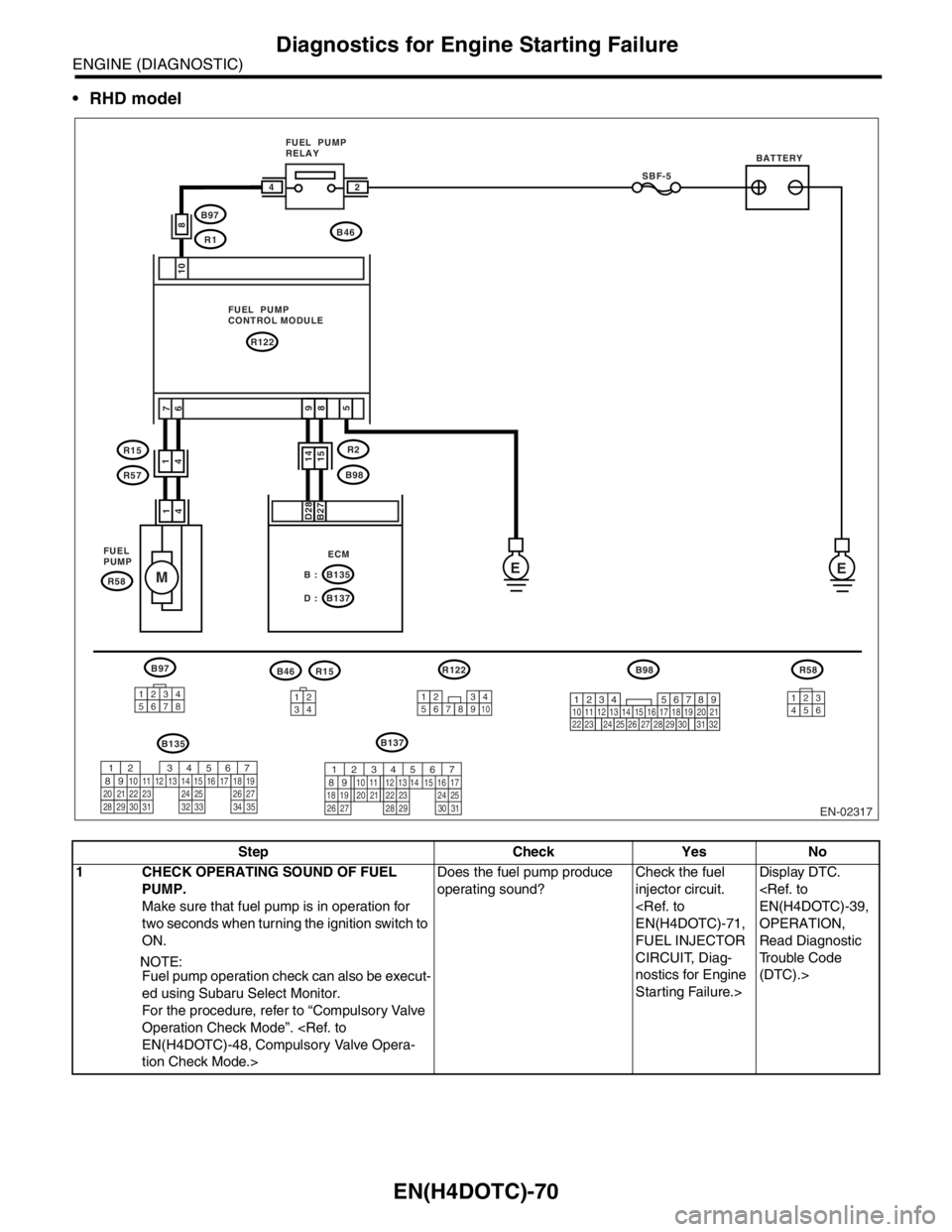
RHD model
Step Check Yes No
1 CHECK OPERATING SOUND OF FUEL
PUMP.
Make sure that fuel pump is in operation for
two seconds when turning the ignition switch to
ON.
NOTE:
Fuel pump operation check can also be execut-
ed using Subaru Select Monitor.
For the procedure, refer to “Compulsory Valve
Operation Check Mode”.
tion Check Mode.>Does the fuel pump produce
operating sound?Check the fuel
injector circuit.
FUEL INJECTOR
CIRCUIT, Diag-
nostics for Engine
Starting Failure.>Display DTC.
OPERATION,
Read Diagnostic
Trouble Code
(DTC).>
EN-02317
B97
B135B137
R122
EE
M
10 7
6
FUEL PUMP
RELAY
FUEL PUMP
CONTROL MODULE
FUEL
PUMP
SBF-5
B46
R122
B135 B :
B137 D :
R15
R57
R58
R2
ECM
B98
B98R58
B97
R1
BATTERY
8
1
4
D28
B27
123456783412123456789102356
24
1
4
9
85
14
14
15
219
32
1234
5610 11 12 13 14 15716
23 3019 20
22 26 27 28 29817
24 3118
25
567
82 1
94 310
24 22 23 2511 12 13 14 15
26 27
2816 17 18 19
20 21
29 30 31 32 33 34 35567
82 1
94 310
22 23 11 12 13 14 15
24 25
2616 17
18 19 20 21
27 28 29 30 31
B46R15
Page 1703 of 2870

EN(H4DOTC)-73
ENGINE (DIAGNOSTIC)
Diagnostics for Engine Starting Failure
Step Check Yes No
1 CHECK OPERATION OF EACH FUEL INJEC-
TOR.
While cranking the engine, check that each
fuel injector emits operating sound.Use a
sound scope or attach a screwdriver to the
injector for this check.Does the fuel pump produce
operating sound?Check the fuel
pressure.
INSPECTION,
Fuel Pressure.>Go to step 2.
2 CHECK POWER SUPPLY TO EACH FUEL
INJECTOR.
1) Turn the ignition switch to OFF.
2) Disconnect the connector from fuel injector.
3) Turn the ignition switch to ON.
4) Measure the power supply voltage between
fuel injector terminal and engine ground.
Connector & terminal
#1 (E5) No. 2 (+) — Engine ground (
−):
#2 (E16) No. 2 (+) — Engine ground (
−):
#3 (E6) No. 2 (+) — Engine ground (
−):
#4 (E17) No. 2 (+) — Engine ground (
−):Is the voltage more than 10 V? Go to step 3.Repair the har-
ness and connec-
tor.
N
OTE:
In this case repair
the following:
Open circuit in
harness between
main relay and fuel
injector connector
Poor contact in
main relay connec-
tor
Poor contact in
coupling connector
Poor contact in
fuel injector con-
nector
3 CHECK HARNESS BETWEEN ECM AND
FUEL INJECTOR CONNECTOR.
1) Disconnect the connector from ECM.
2) Measure the resistance of harness
between ECM and fuel injector connector.
Connector & terminal
(B136) No. 6 — (E5) No. 1:
(B136) No. 5 — (E16) No. 1:
(B136) No. 4 — (E6) No. 1:
(B136) No. 3 — (E6) No. 1:Is the resistance less than 1
Ω?Go to step 4.Repair the har-
ness and connec-
tor.
NOTE:
In this case repair
the following:
Open circuit in
harness between
ECM and fuel
injector connector
Poor contact in
coupling connector
4 CHECK HARNESS BETWEEN ECM AND
FUEL INJECTOR CONNECTOR.
Measure the resistance of harness between
ECM and fuel injector connector.
Connector & terminal
(B136) No. 6 — Chassis ground:
(B136) No. 5 — Chassis ground:
(B136) No. 4 — Chassis ground:
(B136) No. 3 — Chassis ground:Is the resistance less than 1
Ω?Repair ground
short circuit in har-
ness between
ECM and fuel
injector connector.Go to step 5.
5 CHECK EACH FUEL INJECTOR.
1) Turn the ignition switch to OFF.
2) Measure the resistance between each fuel
injector terminals.
Te r m i n a l s
No. 1 — No. 2:Is the resistance 5 — 20 Ω? Go to step 6.Replace the faulty
fuel injector.
6 CHECK POOR CONTACT.
Check poor contact in ECM connector.Is there poor contact in ECM
connector?Repair the poor
contact in ECM
connector.Inspection using
“General Diagnos-
tic Table”
295, INSPEC-
TION, General
Diagnostic Table.>
Page 1710 of 2870

FUJI HEAVY INDUSTRIES LTD. G8080GE3
2004 FORESTER SERVICE MANUAL QUICK REFERENCE INDEX
ENGINE SECTION 2
This service manual has been prepared
to provide SUBARU service personnel
with the necessary information and data
for the correct maintenance and repair
of SUBARU vehicles.
This manual includes the procedures
for maintenance, disassembling, reas-
sembling, inspection and adjustment of
components and diagnostics for guid-
ance of experienced mechanics.
Please peruse and utilize this manual
fully to ensure complete repair work for
satisfying our customers by keeping
their vehicle in optimum condition.
When replacement of parts during
repair work is needed, be sure to use
SUBARU genuine parts.
All information, illustration and specifi-
cations contained in this manual are
based on the latest product information
available at the time of publication
approval.FUEL INJECTION (FUEL SYSTEM) FU(H4DOTC)
EMISSION CONTROL
(AUX. EMISSION CONTROL DEVICE)EC(H4DOTC)
INTAKE (INDUCTION) IN(H4DOTC)
MECHANICAL ME(H4DOTC)
EXHAUST EX(H4DOTC)
COOLING CO(H4DOTC)
LUBRICATION LU(H4DOTC)
SPEED CONTROL SYSTEM SP(H4DOTC)
IGNITION IG(H4DOTC)
STARTING/CHARGING SYSTEM SC(H4DOTC)
ENGINE (DIAGNOSTIC) EN(H4DOTC)
Page 1716 of 2870

EN(H4DOTC)-83
ENGINE (DIAGNOSTIC)
Diagnostic Procedure with Diagnostic Trouble Code (DTC)
Step Check Yes No
1 CHECK HARNESS BETWEEN ECM AND
FRONT OXYGEN (A/F) SENSOR CONNEC-
TOR.
1) Start the engine, and warm-up the engine.
2) Turn the ignition switch to OFF.
3) Disconnect the connector from ECM and
front oxygen (A/F) sensor.
4) Measure the resistance of harness
between ECM and front oxygen (A/F) sensor
connector.
Connector & terminal
(B134)No. 2 — (B262)No. 2:
(B134)No. 3 — (B262)No. 2:Is the resistance less than 1
Ω?Go to step 2.Repair the open
circuit in harness
between ECM and
front oxygen (A/F)
sensor connector.
2 CHECK HARNESS BETWEEN ECM AND
FRONT OXYGEN (A/F) SENSOR CONNEC-
TOR.
Measure the resistance of harness between
ECM and front oxygen (A/F) sensor connector.
Connector & terminal
(B134) No. 33 — (B262) No. 4:
(B134) No. 26 — (B262) No. 3:Is the resistance less than 1
Ω?Go to step 3.Repair the open
circuit in harness
between ECM and
front oxygen (A/F)
sensor connector.
3 CHECK HARNESS BETWEEN ECM AND
FRONT OXYGEN (A/F) SENSOR CONNEC-
TOR.
Measure the resistance of harness between
main relay and front oxygen (A/F) sensor con-
nector.
Connector & terminal
(B47) No. 4 — (B262) No. 1:Is the resistance less than 1
Ω?Go to step 4.Repair the open
circuit in harness
between ECM and
front oxygen (A/F)
sensor connector.
4 CHECK FRONT OXYGEN (A/F) SENSOR.
Measure the resistance between front oxygen
(A/F) sensor connector terminals.
Te r m i n a l s
No. 2 — No. 1:Is the resistance less than 5
Ω?Go to step 5.Replace the front
oxygen (A/F) sen-
sor.
Front Oxygen (A/
F) Sensor.>
5 CHECK POOR CONTACT.
Check poor contact in ECM and front oxygen
(A/F) sensor connector. Is there poor contact in ECM or
front oxygen (A/F) sensor con-
nector?Repair the poor
contact in ECM
and front oxygen
(A/F) sensor.Replace the front
oxygen (A/F) sen-
sor.
Front Oxygen (A/
F) Sensor.>
Page 1718 of 2870

EN(H4DOTC)-85
ENGINE (DIAGNOSTIC)
Diagnostic Procedure with Diagnostic Trouble Code (DTC)
Step Check Yes No
1 CHECK POWER SUPPLY TO FRONT OXY-
GEN (A/F) SENSOR.
1) Turn the ignition switch to OFF.
2) Disconnect the connector from front oxygen
(A/F) sensor.
3) Turn the ignition switch to ON.
4) Measure the voltage between front oxygen
(A/F) sensor connector and engine ground.
Connector & terminal
(B262) No. 1 (+) — Engine ground (
−):Is the voltage more than 10 V? Go to step 2.Repair the power
supply line.
N
OTE:
In this case repair
the following:
Open circuit in
harness between
main relay and
front oxygen (A/F)
sensor
CHECK POOR
CONTACT OF
FRONT OXYGEN
(A/F) SENSOR.
Poor contact in
main relay connec-
tor
2 CHECK GROUND CIRCUIT FOR ECM.
Measure the resistance of harness between
ECM connector and chassis ground.
Connector & terminal
(B134) No. 6 — Chassis ground:
(B134) No. 7 — Chassis ground:Is the resistance less than 5
Ω?Go to step 3.Repair the har-
ness and connec-
tor.
N
OTE:
In this case repair
the following:
Open circuit in
harness between
ECM and engine
ground cable
Poor contact in
ECM connector.
Poor contact in
coupling connector
3 CHECK CURRENT DATA.
1) Start the engine.
2) Read the data of front oxygen (A/F) sensor
heater current using Subaru Select Monitor or
OBD-II general scan tool.
N
OTE:
Subaru Select Monitor
For detailed operation procedure, refer to
“READ CURRENT DATA SHOWN ON DIS-
PLAY FOR ENGINE”.
OBD-II general scan tool
For detailed operation procedures, refer to the
OBD-II General Scan Tool Operation Manual.Is the current more than 0.2 A? Repair poor con-
tact connector.
N
OTE:
In this case repair
the following:
Poor contact in
front oxygen (A/F)
sensor connector
Poor contact in
ECM connector.Go to step 4.
4 CHECK OUTPUT SIGNAL FROM ECM.
1) Start and idle the engine.
2) Measure the voltage between ECM con-
nector and chassis ground.
Connector & terminal
(B134) No. 2 (+) — Chassis ground (
−):Is the voltage less than 1 V? Go to step 6.Go to step 5.
5 CHECK OUTPUT SIGNAL FROM ECM.
Measure the voltage between ECM connector
and chassis ground.
Connector & terminal
(B134) No. 2 (+) — Chassis ground (
−):Does the voltage change by
shaking the harness and con-
nector of ECM while monitor-
ing the value with voltage
meter?Repair the poor
contact in ECM
connector.Go to step 6.