Page 855 of 1833
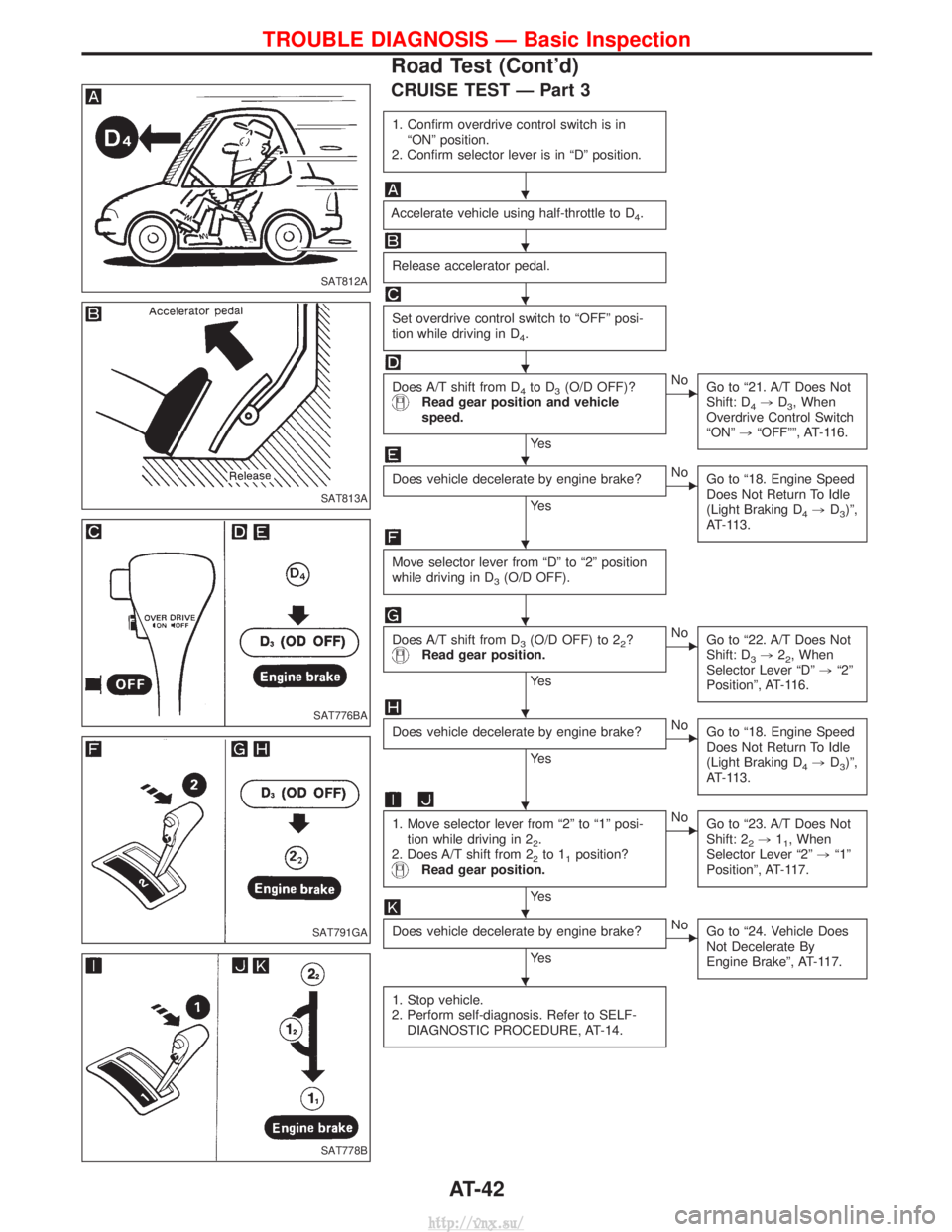
CRUISE TEST Ð Part 3
1. Confirm overdrive control switch is inªONº position.
2. Confirm selector lever is in ªDº position.
Accelerate vehicle using half-throttle to D4.
Release accelerator pedal.
Set overdrive control switch to ªOFFº posi-
tion while driving in D
4.
Does A/T shift from D4to D3(O/D OFF)?Read gear position and vehicle
speed.
Ye s
ENo Go to ª21. A/T Does Not
Shift: D
4,D3, When
Overdrive Control Switch
ªONº ,ªOFFºº, AT-116.
Does vehicle decelerate by engine brake?
Ye s
ENo
Go to ª18. Engine Speed
Does Not Return To Idle
(Light Braking D
4,D3)º,
AT-113.
Move selector lever from ªDº to ª2º position
while driving in D
3(O/D OFF).
Does A/T shift from D3(O/D OFF) to 22?Read gear position.
Ye s
ENo Go to ª22. A/T Does Not
Shift: D
3,22, When
Selector Lever ªDº ,ª2º
Positionº, AT-116.
Does vehicle decelerate by engine brake?
Ye s
ENo Go to ª18. Engine Speed
Does Not Return To Idle
(Light Braking D
4,D3)º,
AT-113.
1. Move selector lever from ª2º to ª1º posi- tion while driving in 2
2.
2. Does A/T shift from 2
2to 11position?Read gear position.
Ye s
ENo Go to ª23. A/T Does Not
Shift: 2
2,11, When
Selector Lever ª2º ,ª1º
Positionº, AT-117.
Does vehicle decelerate by engine brake?
Ye s
ENo Go to ª24. Vehicle Does
Not Decelerate By
Engine Brakeº, AT-117.
1. Stop vehicle.
2. Perform self-diagnosis. Refer to SELF- DIAGNOSTIC PROCEDURE, AT-14.
SAT812A
SAT813A
SAT776BA
SAT791GA
SAT778B
H
H
H
H
H
H
H
H
H
H
H
TROUBLE DIAGNOSIS Ð Basic Inspection
Road Test (Cont'd)
AT-42
http://vnx.su/
Page 911 of 1833
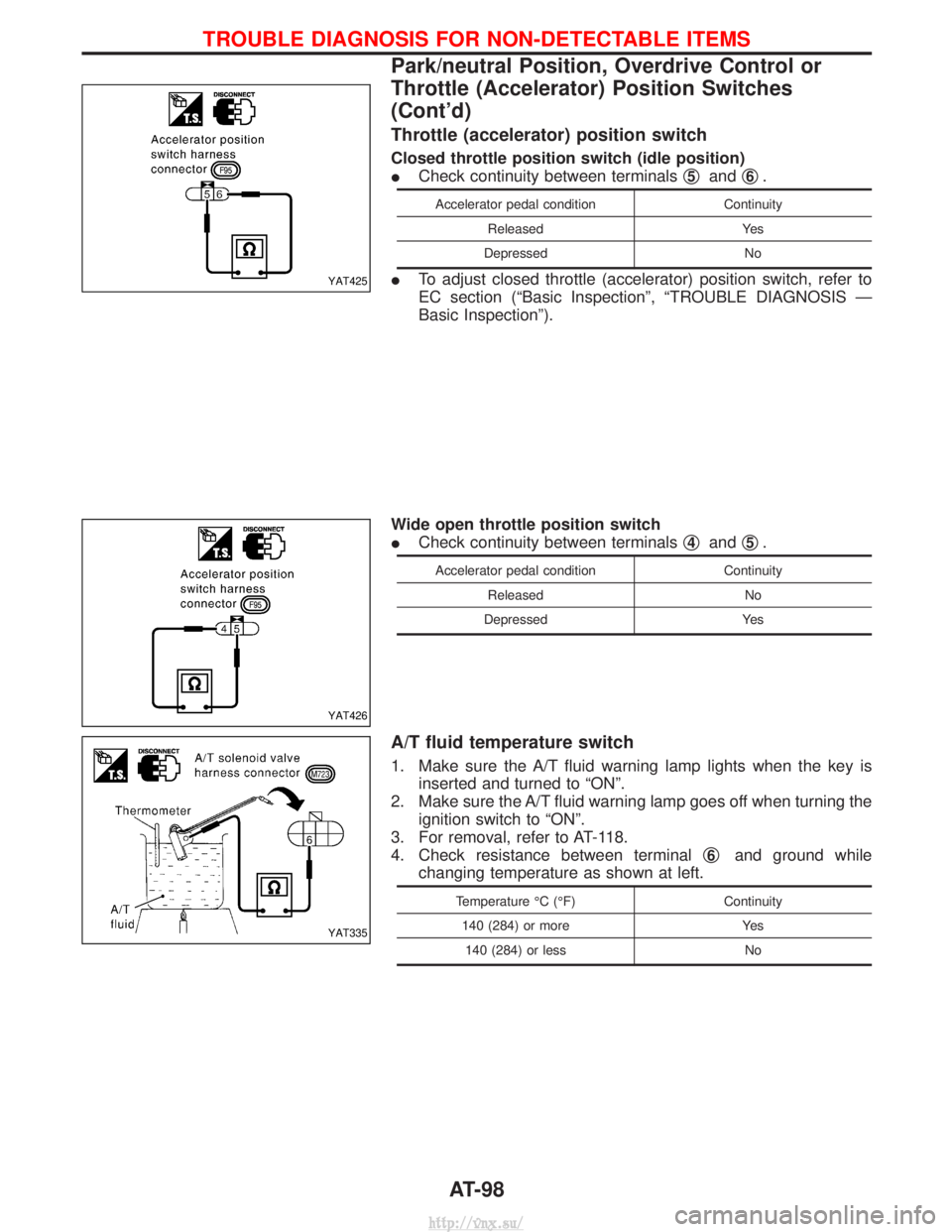
Throttle (accelerator) position switch
Closed throttle position switch (idle position)
ICheck continuity between terminals q
5andq6.
Accelerator pedal condition
Continuity
Released Yes
Depressed No
ITo adjust closed throttle (accelerator) position switch, refer to
EC section (ªBasic Inspectionº, ªTROUBLE DIAGNOSIS Ð
Basic Inspectionº).
Wide open throttle position switch
I Check continuity between terminals q
4andq5.
Accelerator pedal condition
Continuity
Released No
Depressed Yes
A/T fluid temperature switch
1. Make sure the A/T fluid warning lamp lights when the key is
inserted and turned to ªONº.
2. Make sure the A/T fluid warning lamp goes off when turning the ignition switch to ªONº.
3. For removal, refer to AT-118.
4. Check resistance between terminal q
6and ground while
changing temperature as shown at left.
Temperature ÉC (ÉF) Continuity
140 (284) or more Yes
140 (284) or less No
YAT425
YAT426
YAT335
TROUBLE DIAGNOSIS FOR NON-DETECTABLE ITEMS
Park/neutral Position, Overdrive Control or
Throttle (Accelerator) Position Switches
(Cont'd)
AT-98
http://vnx.su/
Page 926 of 1833
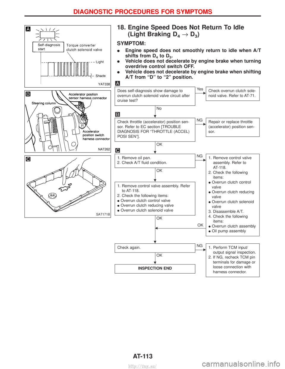
18. Engine Speed Does Not Return To Idle(Light Braking D
4®D3)
SYMPTOM:
I Engine speed does not smoothly return to idle when A/T
shifts from D
4to D3.
I Vehicle does not decelerate by engine brake when turning
overdrive control switch OFF.
I Vehicle does not decelerate by engine brake when shifting
A/T from ªDº to ª2º position.
Does self-diagnosis show damage to
overrun clutch solenoid valve circuit after
cruise test?
No
EYe s
Check overrun clutch sole-
noid valve. Refer to AT-71.
Check throttle (accelerator) position sen-
sor. Refer to EC section [TROUBLE
DIAGNOSIS FOR ªTHROTTLE (ACCEL)
POSI SENº].
OK
ENGRepair or replace throttle
(accelerator) position sen-
sor.
1. Remove oil pan.
2. Check A/T fluid condition.
OK
ENG 1. Remove control valve
assembly. Refer to
AT-118.
2. Check the following items:
I Overrun clutch control
valve
I Overrun clutch reducing
valve
I Overrun clutch solenoid
valve
3. Disassemble A/T.
4. Check the following items:
I Overrun clutch assembly
I Oil pump assembly
1. Remove control valve assembly. Refer
to AT-118.
2. Check the following items:
I Overrun clutch control valve
I Overrun clutch reducing valve
I Overrun clutch solenoid valve
OK
FOK
Check again.
OK
ENG 1. Perform TCM input/
output signal inspection.
2. If NG, recheck TCM pin terminals for damage or
loose connection with
harness connector.
INSPECTION END
YAT338
NAT262
SAT171B
H
H
H
HH
H
DIAGNOSTIC PROCEDURES FOR SYMPTOMS
AT-113
http://vnx.su/
Page 930 of 1833
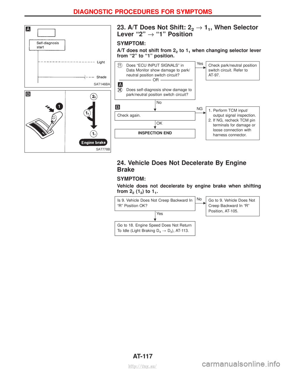
23. A/T Does Not Shift: 22®11, When Selector
Lever ª2º ®ª1º Position
SYMPTOM:
A/T does not shift from 22to 11when changing selector lever
from ª2º to ª1º position.
Does ªECU INPUT SIGNALSº in
Data Monitor show damage to park/
neutral position switch circuit?
---------------------------------------------------------------------------------------------------------------------- -OR -----------------------------------------------------------------------------------------------------------------------
Does self-diagnosis show damage to
park/neutral position switch circuit?
No
EYe s
Check park/neutral position
switch circuit. Refer to
AT-97.
Check again.
OK
ENG1. Perform TCM input/
output signal inspection.
2. If NG, recheck TCM pin terminals for damage or
loose connection with
harness connector.
INSPECTION END
24. Vehicle Does Not Decelerate By Engine
Brake
SYMPTOM:
Vehicle does not decelerate by engine brake when shifting
from 2
2(12)to11.
Is 9. Vehicle Does Not Creep Backward In
ªRº Position OK?
Ye s
ENo Go to 9. Vehicle Does Not
Creep Backward In ªRº
Position, AT-105.
Go to 18. Engine Speed Does Not Return
To Idle (Light Braking D
4,D3), AT-113.
SAT146BA
SAT778B
H
H
H
DIAGNOSTIC PROCEDURES FOR SYMPTOMS
AT-117
http://vnx.su/
Page 936 of 1833
ITighten bolts securing transmission.
Bolt No. Tightening torque
N×m (kg-m, ft-lb) Bolt length ªº
mm (in)
q
139 - 49 (4.0 - 5.0, 29 - 36) 58.0 (2.28)
q
229 - 39 (3.0 - 4.0, 22 - 29) 90.0 (3.54)
q
318 - 22 (1.8 - 2.2, 13 - 16) 16.0 (0.63)
q
43 - 4 (0.3 - 0.4, 2.2 - 2.9) 12.0 (0.47)
q
529 - 39 (3.0 - 4.0, 22 - 29) 35.0 (1.38)
IReinstall any part removed.
I Check fluid level in transmission.
I Move selector lever through all positions to be sure that trans-
mission operates correctly.
With parking brake applied, rotate engine at idling. Move selec-
tor lever through ªNº to ªDº, to ª2º, to ª1º and to ªRº positions.
A slight shock should be felt by hand gripping selector each
time transmission is shifted.
I Perform road test. Refer to ªROAD TESTº, AT-32.NAT287
SAT638A
REMOVAL AND INSTALLATION
Installation (Cont'd)
AT-123
http://vnx.su/
Page 963 of 1833
DISASSEMBLY
1. Remove valves at parallel pins.
IDo not use a magnetic hand.
a. Use a wire paper clip to push out parallel pins.
b. Remove parallel pins while pressing their corresponding plugs and sleeves.
I Remove plug slowly to prevent internal parts from jumping
out.
c. Place mating surface of valve facedown, and remove internal parts.
I If a valve is hard to remove, place valve body facedown
and lightly tap it with a soft hammer.
I Be careful not to drop or damage valves and sleeves.
2. Remove valves at retainer plates.
a. Pry out retainer plate with wire paper clip.
SAT834A
SAT822A
SAT823A
SAT824A
SAT825A
REPAIR FOR COMPONENT PARTS
Control Valve Upper Body (Cont'd)
AT-150
http://vnx.su/
Page 964 of 1833
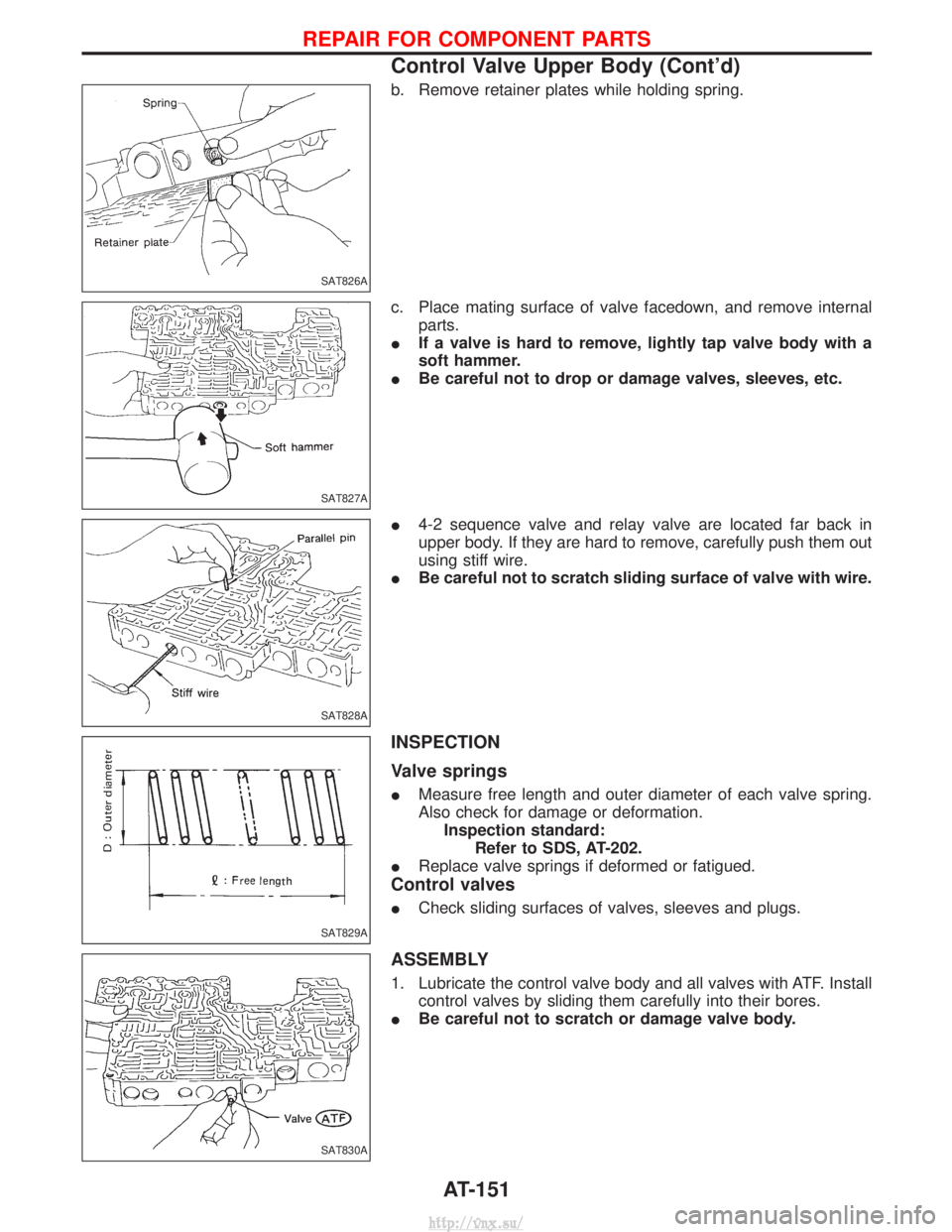
b. Remove retainer plates while holding spring.
c. Place mating surface of valve facedown, and remove internalparts.
I If a valve is hard to remove, lightly tap valve body with a
soft hammer.
I Be careful not to drop or damage valves, sleeves, etc.
I 4-2 sequence valve and relay valve are located far back in
upper body. If they are hard to remove, carefully push them out
using stiff wire.
I Be careful not to scratch sliding surface of valve with wire.
INSPECTION
Valve springs
IMeasure free length and outer diameter of each valve spring.
Also check for damage or deformation.
Inspection standard: Refer to SDS, AT-202.
I Replace valve springs if deformed or fatigued.
Control valves
ICheck sliding surfaces of valves, sleeves and plugs.
ASSEMBLY
1. Lubricate the control valve body and all valves with ATF. Install
control valves by sliding them carefully into their bores.
I Be careful not to scratch or damage valve body.
SAT826A
SAT827A
SAT828A
SAT829A
SAT830A
REPAIR FOR COMPONENT PARTS
Control Valve Upper Body (Cont'd)
AT-151
http://vnx.su/
Page 965 of 1833
IWrap a small screwdriver with vinyl tape and use it to insert the
valves into proper position.
Pressure regulator valve
IIf pressure regulator plug is not centered properly, sleeve can-
not be inserted into bore in upper body.
If this happens, use vinyl tape wrapped screwdriver to center
sleeve until it can be inserted.
I Turn sleeve slightly while installing.
Accumulator control plug
IAlign protrusion of accumulator control sleeve with notch in
plug.
I Align parallel pin groove in plug with parallel pin, and install
accumulator control valve.
2. Install parallel pins and retainer plates.
I While pushing plug, install parallel pin.
SAT831A
SAT832A
SAT833A
SAT834A
SAT823A
REPAIR FOR COMPONENT PARTS
Control Valve Upper Body (Cont'd)
AT-152
http://vnx.su/