2004 NISSAN TERRANO light
[x] Cancel search: lightPage 619 of 1833
DTC and MI Detection Logic
When a malfunction is detected for the first time, the malfunction (DTC) is stored in the ECM memory.
The MI will light up each time the ECM detects a malfunction. However, if the same malfunction is experienced
in two consecutive driving patterns and the engine is still running, the MI will stay lit up. For a description of
diagnostic items causing the MI to light up, refer to ªTROUBLE DIAGNOSIS Ð INDEXº, EC-313.
Diagnostic Trouble Code (DTC)
HOW TO READ DTC
The DTC can be read by the following methods.
Without CONSULT-II
ECM displays the DTC by a set of four digit numbers with MI illumination in the diagnostic test mode II (Self-
diagnostic results). Example: 0102, 0103, 0104, etc.
With CONSULT-II
CONSULT-II displays the DTC in ªSELF-DIAG RESULTSº mode. Examples: P0100, P0115, P0500, etc.
These DTCs are prescribed by ISO15031-6.
(CONSULT-II also displays the malfunctioning component or system.)
IOutput of the trouble code means that the indicated circuit has a malfunction. However, in the Mode
II it does not indicate whether the malfunction is still occurring or occurred in the past and returned
to normal.
CONSULT-II can identify them. Therefore, using CONSULT-II (if available) is recommended.
HOW TO ERASE DTC
How to Erase DTC (
With CONSULT-II)
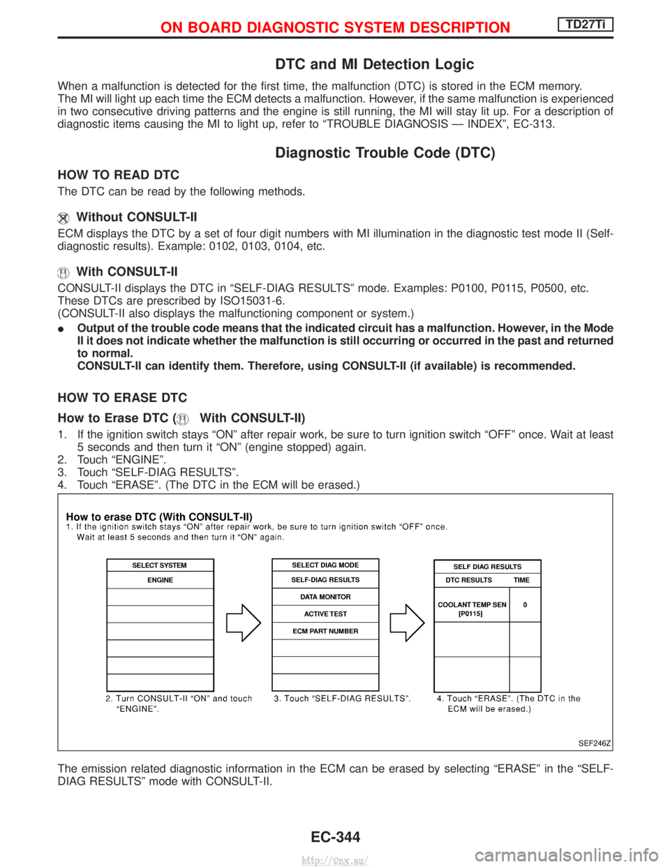
1. If the ignition switch stays ªONº after repair work, be sure to turn ignition switch ªOFFº once. Wait at least
5 seconds and then turn it ªONº (engine stopped) again.
2. Touch ªENGINEº.
3. Touch ªSELF-DIAG RESULTSº.
4. Touch ªERASEº. (The DTC in the ECM will be erased.)
The emission related diagnostic information in the ECM can be erased by selecting ªERASEº in the ªSELF-
DIAG RESULTSº mode with CONSULT-II.
SEF246Z
ON BOARD DIAGNOSTIC SYSTEM DESCRIPTIONTD27Ti
EC-344
http://vnx.su/
Page 620 of 1833
How to Erase DTC (Without CONSULT-II)
1. If the ignition switch stays ªONº after repair work, be sure to turn ignition switch ªOFFº once. Wait at least5 seconds and then turn it ªONº (engine stopped) again.
2. Change the diagnostic test mode from Mode II to Mode I by using the data link connector. (See EC-346.)
The emission related diagnostic information in the ECM can be erased by changing the diagnostic test mode.
I If the battery is disconnected, the emission-related diagnostic information will be lost after approx.
24 hours.
I Erasing the emission-related diagnostic information using CONSULT-II is easier and quicker than
switching the diagnostic test mode using the data link connector.
Malfunction Indicator (MI)
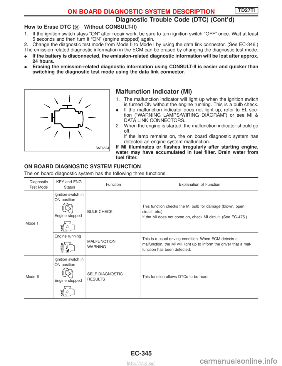
1. The malfunction indicator will light up when the ignition switch
is turned ON without the engine running. This is a bulb check.
I If the malfunction indicator does not light up, refer to EL sec-
tion (ªWARNING LAMPS/WIRING DIAGRAMº) or see MI &
DATA LINK CONNECTORS.
2. When the engine is started, the malfunction indicator should go off.
If the lamp remains on, the on board diagnostic system has
detected an engine system malfunction.
If MI illuminates or flashes irregularly after starting engine,
water may have accumulated in fuel filter. Drain water from
fuel filter.
ON BOARD DIAGNOSTIC SYSTEM FUNCTION
The on board diagnostic system has the following three functions.
Diagnostic
Test Mode KEY and ENG.
Status Function Explanation of Function
Mode I Ignition switch in
ON position
Engine stoppedBULB CHECK
This function checks the MI bulb for damage (blown, open
circuit, etc.).
If the MI does not come on, check MI circuit. (See EC-475.)
Engine running
MALFUNCTION
WARNING This is a usual driving condition. When ECM detects a
malfunction, the MI will light up to inform the driver that a mal-
function has been detected.
Mode II Ignition switch in
ON position
Engine stopped
SELF-DIAGNOSTIC
RESULTS
This function allows DTCs to be read.
SAT652J
ON BOARD DIAGNOSTIC SYSTEM DESCRIPTIONTD27Ti
Diagnostic Trouble Code (DTC) (Cont'd)
EC-345
http://vnx.su/
Page 624 of 1833
RELATIONSHIP BETWEEN MI, DTC, CONSULT-II AND DRIVING PATTERNS
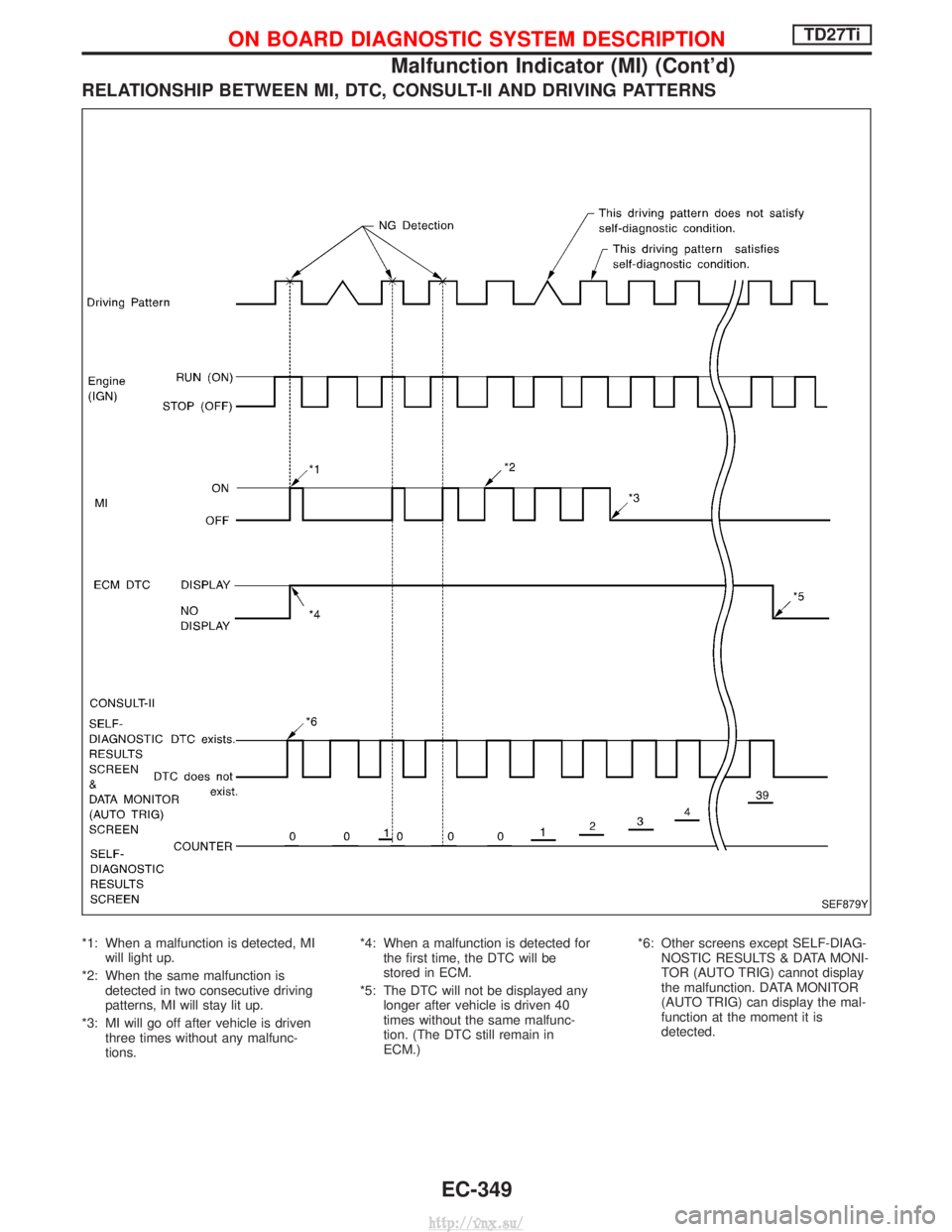
*1: When a malfunction is detected, MIwill light up.
*2: When the same malfunction is detected in two consecutive driving
patterns, MI will stay lit up.
*3: MI will go off after vehicle is driven three times without any malfunc-
tions. *4: When a malfunction is detected for
the first time, the DTC will be
stored in ECM.
*5: The DTC will not be displayed any longer after vehicle is driven 40
times without the same malfunc-
tion. (The DTC still remain in
ECM.) *6: Other screens except SELF-DIAG-
NOSTIC RESULTS & DATA MONI-
TOR (AUTO TRIG) cannot display
the malfunction. DATA MONITOR
(AUTO TRIG) can display the mal-
function at the moment it is
detected.
SEF879Y
ON BOARD DIAGNOSTIC SYSTEM DESCRIPTIONTD27Ti
Malfunction Indicator (MI) (Cont'd)
EC-349
http://vnx.su/
Page 634 of 1833
Work Flow
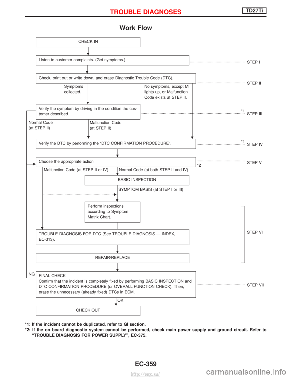
CHECK IN
Listen to customer complaints. (Get symptoms.).................................................STEP I
Check, print out or write down, and erase Diagnostic Trouble Code (DTC).
........................................... STEP II
Symptoms
collected. No symptoms, except MI
lights up, or Malfunction
Code exists at STEP II.
Verify the symptom by driving in the condition the cus-
tomer described.
H
*1
........................................................................\
..................... STEP III
Normal Code
(at STEP II)
Malfunction Code
(at STEP II)
Verify the DTC by performing the ªDTC CONFIRMATION PROCEDUREº.
*1
........................................... STEP IV
EChoose the appropriate action.
Malfunction Code (at STEP II or IV) Normal Code (at both STEP II and IV) ...........................................
*2 STEP V
BASIC INSPECTION
SYMPTOM BASIS (at STEP I or III)
................................................................
E
Perform inspections
according to Symptom
Matrix Chart.
TROUBLE DIAGNOSIS FOR DTC (See TROUBLE DIAGNOSIS Ð INDEX,
EC-313).STEP VI
REPAIR/REPLACE
NGFINAL CHECK
Confirm that the incident is completely fixed by performing BASIC INSPECTION and
DTC CONFIRMATION PROCEDURE (or OVERALL FUNCTION CHECK). Then,
erase the unnecessary (already fixed) DTCs in ECM.
OK ...........................................
STEP VII
CHECK OUT
*1: If the incident cannot be duplicated, refer to GI section.
*2: If the on board diagnostic system cannot be performed, check main power supply and ground circuit. Refer to ªTROUBLE DIAGNOSIS FOR POWER SUPPLYº, EC-375.
H
H
H
H
H
H
H
H
H
H
H
TROUBLE DIAGNOSESTD27Ti
EC-359
http://vnx.su/
Page 641 of 1833
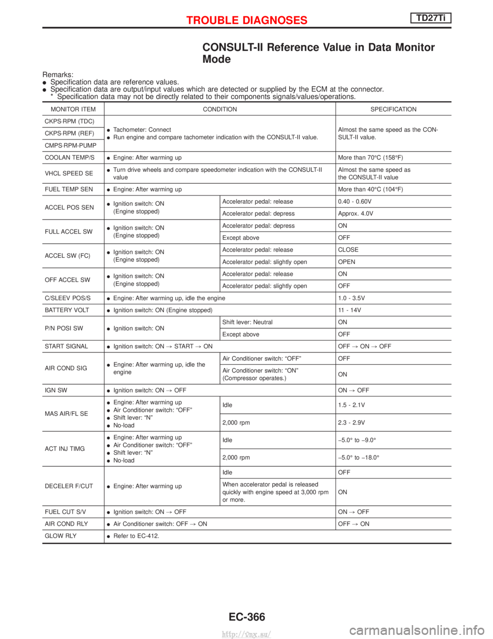
CONSULT-II Reference Value in Data Monitor
Mode
Remarks:
ISpecification data are reference values.
I Specification data are output/input values which are detected or supplied by the ECM at the connector.
* Specification data may not be directly related to their components signals/values/operations.
MONITOR ITEM CONDITION SPECIFICATION
CKPS×RPM (TDC) ITachometer: Connect
I Run engine and compare tachometer indication with the CONSULT-II value. Almost the same speed as the CON-
SULT-II value.
CKPS×RPM (REF)
CMPS×RPM-PUMP
COOLAN TEMP/S
IEngine: After warming up More than 70ÉC (158ÉF)
VHCL SPEED SE I
Turn drive wheels and compare speedometer indication with the CONSULT-II
value Almost the same speed as
the CONSULT-II value
FUEL TEMP SEN IEngine: After warming up More than 40ÉC (104ÉF)
ACCEL POS SEN I
Ignition switch: ON
(Engine stopped) Accelerator pedal: release 0.40 - 0.60V
Accelerator pedal: depress Approx. 4.0V
FULL ACCEL SW I
Ignition switch: ON
(Engine stopped) Accelerator pedal: depress ON
Except above OFF
ACCEL SW (FC) I
Ignition switch: ON
(Engine stopped) Accelerator pedal: release CLOSE
Accelerator pedal: slightly open OPEN
OFF ACCEL SW I
Ignition switch: ON
(Engine stopped) Accelerator pedal: release ON
Accelerator pedal: slightly open OFF
C/SLEEV POS/S IEngine: After warming up, idle the engine 1.0 - 3.5V
BATTERY VOLT IIgnition switch: ON (Engine stopped) 11 - 14V
P/N POSI SW IIgnition switch: ON Shift lever: Neutral ON
Except above OFF
START SIGNAL IIgnition switch: ON ,START ,ON OFF ,ON ,OFF
AIR COND SIG I
Engine: After warming up, idle the
engine Air Conditioner switch: ªOFFº OFF
Air Conditioner switch: ªONº
(Compressor operates.)
ON
IGN SW IIgnition switch: ON ,OFF ON ,OFF
MAS AIR/FL SE I
Engine: After warming up
I Air Conditioner switch: ªOFFº
I Shift lever: ªNº
I No-load Idle 1.5 - 2.1V
2,000 rpm 2.3 - 2.9V
ACT INJ TIMG I
Engine: After warming up
I Air Conditioner switch: ªOFFº
I Shift lever: ªNº
I No-load Idle þ5.0É to þ9.0É
2,000 rpm þ5.0É to þ18.0É
DECELER F/CUT IEngine: After warming up Idle OFF
When accelerator pedal is released
quickly with engine speed at 3,000 rpm
or more.
ON
FUEL CUT S/V IIgnition switch: ON ,OFF ON ,OFF
AIR COND RLY IAir Conditioner switch: OFF ,ON OFF ,ON
GLOW RLY IRefer to EC-412.
TROUBLE DIAGNOSESTD27Ti
EC-366
http://vnx.su/
Page 702 of 1833
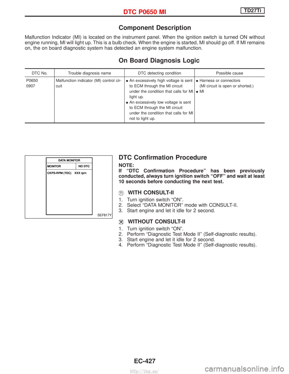
Component Description
Malfunction Indicator (MI) is located on the instrument panel. When the ignition switch is turned ON without
engine running, MI will light up. This is a bulb check. When the engine is started, MI should go off. If MI remains
on, the on board diagnostic system has detected an engine system malfunction.
On Board Diagnosis Logic
DTC No.Trouble diagnosis name DTC detecting condition Possible cause
P0650
0907 Malfunction indicator (MI) control cir-
cuit I
An excessively high voltage is sent
to ECM through the MI circuit
under the condition that calls for MI
light up.
I An excessively low voltage is sent
to ECM through the MI circuit
under the condition that calls for MI
not to light up. I
Harness or connectors
(MI circuit is open or shorted.)
I MI
DTC Confirmation Procedure
NOTE:
If ªDTC Confirmation Procedureº has been previously
conducted, always turn ignition switch ªOFFº and wait at least
10 seconds before conducting the next test.
WITH CONSULT-II
1. Turn ignition switch ªONº.
2. Select ªDATA MONITORº mode with CONSULT-II.
3. Start engine and let it idle for 2 second.
WITHOUT CONSULT-II
1. Turn ignition switch ªONº.
2. Perform ªDiagnostic Test Mode IIº (Self-diagnostic results).
3. Start engine and let it idle for 2 second.
4. Perform ªDiagnostic Test Mode IIº (Self-diagnostic results).
SEF817Y
DTC P0650 MITD27Ti
EC-427
http://vnx.su/
Page 753 of 1833
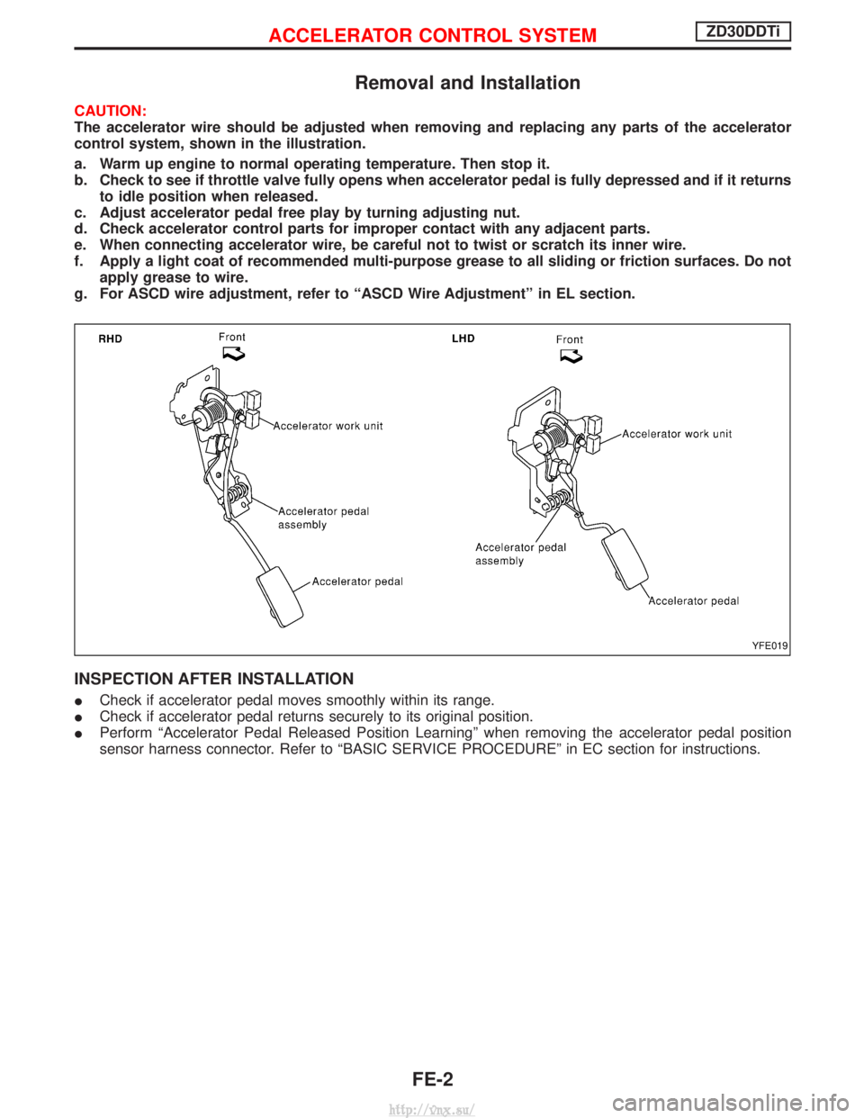
Removal and Installation
CAUTION:
The accelerator wire should be adjusted when removing and replacing any parts of the accelerator
control system, shown in the illustration.
a. Warm up engine to normal operating temperature. Then stop it.
b. Check to see if throttle valve fully opens when accelerator pedal is fully depressed and if it returnsto idle position when released.
c. Adjust accelerator pedal free play by turning adjusting nut.
d. Check accelerator control parts for improper contact with any adjacent parts.
e. When connecting accelerator wire, be careful not to twist or scratch its inner wire.
f. Apply a light coat of recommended multi-purpose grease to all sliding or friction surfaces. Do not apply grease to wire.
g. For ASCD wire adjustment, refer to ªASCD Wire Adjustmentº in EL section.
INSPECTION AFTER INSTALLATION
I Check if accelerator pedal moves smoothly within its range.
I Check if accelerator pedal returns securely to its original position.
I Perform ªAccelerator Pedal Released Position Learningº when removing the accelerator pedal position
sensor harness connector. Refer to ªBASIC SERVICE PROCEDUREº in EC section for instructions.
YFE019
ACCELERATOR CONTROL SYSTEMZD30DDTi
FE-2
http://vnx.su/
Page 775 of 1833
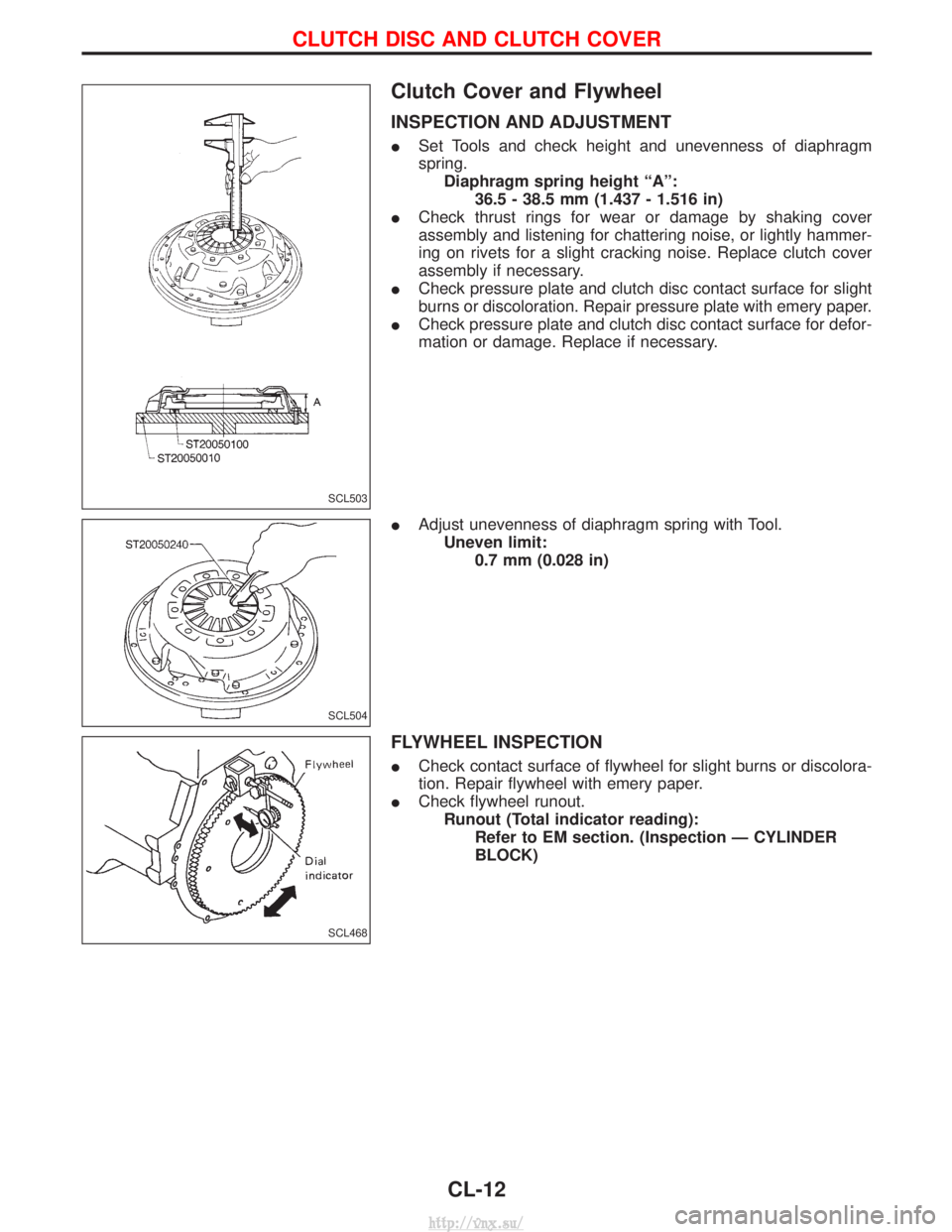
Clutch Cover and Flywheel
INSPECTION AND ADJUSTMENT
ISet Tools and check height and unevenness of diaphragm
spring.
Diaphragm spring height ªAº: 36.5 - 38.5 mm (1.437 - 1.516 in)
I Check thrust rings for wear or damage by shaking cover
assembly and listening for chattering noise, or lightly hammer-
ing on rivets for a slight cracking noise. Replace clutch cover
assembly if necessary.
I Check pressure plate and clutch disc contact surface for slight
burns or discoloration. Repair pressure plate with emery paper.
I Check pressure plate and clutch disc contact surface for defor-
mation or damage. Replace if necessary.
I Adjust unevenness of diaphragm spring with Tool.
Uneven limit: 0.7 mm (0.028 in)
FLYWHEEL INSPECTION
ICheck contact surface of flywheel for slight burns or discolora-
tion. Repair flywheel with emery paper.
I Check flywheel runout.
Runout (Total indicator reading): Refer to EM section. (Inspection Ð CYLINDER
BLOCK)
SCL503
SCL504
SCL468
CLUTCH DISC AND CLUTCH COVER
CL-12
http://vnx.su/