2004 NISSAN TERRANO light
[x] Cancel search: lightPage 786 of 1833
IRaise the unit with a hoist.
I Position the transmission assembly on a portable jack and
secure it with a suitable tool.
Lift the assembly until the gearbox input shaft faces its hous-
ing.
Move the assembly towards the engine. The assembly must be
rotated slightly so that the starter motor housing clears the
projection on the companion floor. Insert input shaft into its
housing (slightly raising the rear of the transfer box may facili-
tate the introduction of the shaft into its housing).
I Tighten the screws securing the gearbox to the engine.
:39-49N ×m (4.0 - 5.0 kg-m, 29 - 36 ft-lb)
I Connect the electrical wiring. Secure with the respective clips.
I Fit the RPM-sensor to the transmission upper side.
I Fit the exhaust pipe support bracket to the transfer box.
:13-16N ×m (1.3 - 1.6 kg-m ,9-12ft-lb)
I Fit the starter motor. Secure the earth wire to the starter motor
lower screw.
:31-41N ×m (3.2 - 4.2 kg-m, 23 - 30 ft-lb)
I Fit the clutch slave cylinder.
:30-40N ×m (3.1 - 4.1 kg-m, 22 - 30 ft-lb)
I Install fourth crossmember (Note the ªfrontº mark).
Crossmember fixing bolts to chassis:
:41-52N ×m (4.2 - 5.3 kg-m, 30 - 38 ft-lb)
Crossmember fixing bolts to transmission:
:68-87N ×m (6.9 - 8.9 kg-m, 50 - 64 ft-lb)
I Take away the portable jack holding boxes assembly.
I Install fifth crossmember.
:59-78N ×m (6.0 - 8.0 kg-m, 43 - 58 ft-lb)
I Install third crossmember.
: Screws: 41 - 52 N ×m (4.2 - 5.3 kg-m,
30 - 38 ft-lb)
Nuts: 68 - 87 N ×m (6.9 - 8.9 kg-m,
50 - 64 ft-lb)
I Install torsion bar springs. Ð Refer to FA section.
I Install front and rear propeller shafts. Ð Refer to PD section.
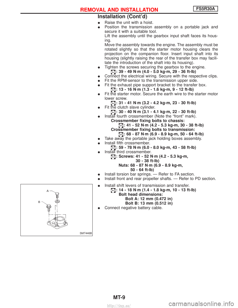
I Install shift levers of transmission and transfer.
:14-18N ×m (1.4 - 1.8 kg-m, 10 - 13 ft-lb)
Bolt head dimensions: Bolt A: 12 mm (0.472 in)
Bolt B: 13 mm (0.512 in)
I Connect negative battery cable.
SMT446B
REMOVAL AND INSTALLATIONFS5R30A
Installation (Cont'd)
MT-9
http://vnx.su/
Page 791 of 1833
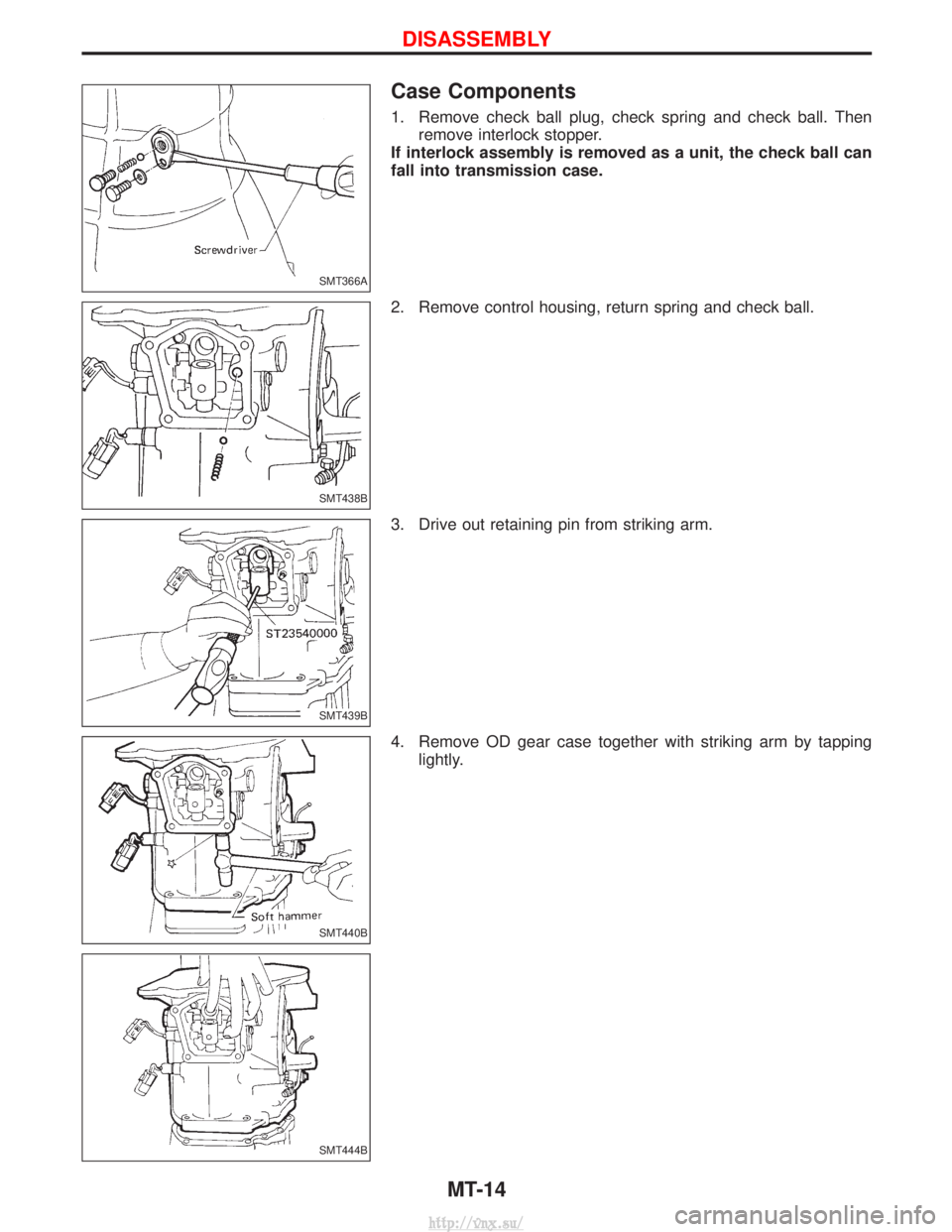
Case Components
1. Remove check ball plug, check spring and check ball. Thenremove interlock stopper.
If interlock assembly is removed as a unit, the check ball can
fall into transmission case.
2. Remove control housing, return spring and check ball.
3. Drive out retaining pin from striking arm.
4. Remove OD gear case together with striking arm by tapping lightly.
SMT366A
SMT438B
SMT439B
SMT440B
SMT444B
DISASSEMBLY
MT-14
http://vnx.su/
Page 792 of 1833
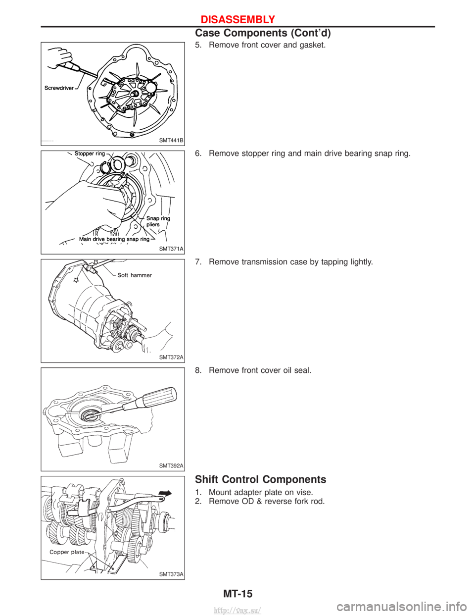
5. Remove front cover and gasket.
6. Remove stopper ring and main drive bearing snap ring.
7. Remove transmission case by tapping lightly.
8. Remove front cover oil seal.
Shift Control Components
1. Mount adapter plate on vise.
2. Remove OD & reverse fork rod.
SMT441B
SMT371A
SMT372A
SMT392A
SMT373A
DISASSEMBLY
Case Components (Cont'd)MT-15
http://vnx.su/
Page 815 of 1833
Park/neutral Position, Overdrive Control or
Throttle (Accelerator) Position Switches ...................93
DIAGNOSTIC PROCEDURES FOR SYMPTOMS ........99
1. SPORT Indicator Lamp Does Not Come On ........99
2. SPORT or SNOW Indicator Lamp Does Not Come On.................................................................100
3. O/D OFF Indicator Lamp Does Not Come On....100
4. SPORT Indicator Lamp Does Not Come On ......101
5. Engine Cannot Be Started In ²P² and ²N²
Position....................................................................102
6. In ²P² Position, Vehicle Moves Forward Or
Backward When Pushed.........................................102
7. In ²N² Position, Vehicle Moves ...........................103
8. Large Shock. ²N² ->²R² Position .......................104
9. Vehicle Does Not Creep Backward In ²R²
Position....................................................................105
10. Vehicle Does Not Creep Forward In ²D² ,²2²
Or ²1² Position.........................................................106
11. Vehicle Cannot Be Started From D
1.................107
12. A/T Does Not Shift: D
1-> D2Or Does Not
Kickdown: D
4-> D2..................................................108
13. A/T Does Not Shift: D
2-> D3............................109
14. A/T Does Not Shift: D
3-> D4............................. 110
15. A/T Does Not Perform Lock-up ......................... 111
16. A/T Does Not Hold Lock-up Condition .............. 112
17. Lock-up Is Not Released ................................... 112
18. Engine Speed Does Not Return To Idle (Light Braking D
4-> D3)..................................................... 113
19. Vehicle Does Not Start From D
1....................... 114
20. A/T Does Not Shift: D
2-> D1When
Depressing Accelerator Pedal................................. 115
21. A/T Does Not Shift: D
4-> D3, When
Overdrive Control Switch ²ON² ->²OFF² ............... 116
22. A/T Does Not Shift: D
3-> 22, When Selector
Lever ²D² ->²2² Position......................................... 116
23. A/T Does Not Shift: 2
2-> 11, When Selector
Lever ²2² ->²1² Position ......................................... 117
24. Vehicle Does Not Decelerate By Engine
Brake........................................................................\
117 ON-VEHICLE SERVICE
.............................................. 118
Control Valve Assembly and Accumulators ............. 118
Revolution Sensor Replacement ............................. 119
Rear Oil Seal Replacement ..................................... 119
Parking Components Inspection.............................. 119
Park/neutral Position Switch Adjustment ................. 119
Manual Control Linkage Adjustment........................120
REMOVAL AND INSTALLATION ................................121
Removal ...................................................................121
Installation ................................................................122
MAJOR OVERHAUL ...................................................124
Oil Channel ..............................................................126
Locations of Needle Bearings, Thrust Washers
and Snap Rings .......................................................127
DISASSEMBLY ............................................................128
Disassembly.............................................................128
REPAIR FOR COMPONENT PARTS ..........................139
Oil Pump ..................................................................139
Control Valve Assembly ...........................................143
Control Valve Upper Body .......................................149
Control Valve Lower Body .......................................154
Reverse Clutch ........................................................156
High Clutch ..............................................................160
Forward and Overrun Clutches ...............................162
Low & Reverse Brake..............................................166
Forward Clutch Drum Assembly ..............................170
Rear Internal Gear and Forward Clutch Hub ..........173
Band Servo Piston Assembly ..................................176
Parking Pawl Components ......................................180
ASSEMBLY ..................................................................182
Assembly (1) ............................................................182
Adjustment ...............................................................190
Assembly (2) ............................................................193
A/T FLUID COOLER SYSTEM ...................................200
A/T Fluid Cooler.......................................................200
SERVICE DATA AND SPECIFICATIONS (SDS) ........201
General Specifications .............................................201
Specifications and Adjustment.................................201
When you read wiring diagrams:
I Read GI section, ªHOW TO READ WIRING DIAGRAMSº.
I See EL section, ªPOWER SUPPLY ROUTINGº for power distribution circuit.
When you perform trouble diagnoses, read GI section, ªHOW TO FOLLOW FLOW CHART IN
TROUBLE DIAGNOSESº and ªHOW TO PERFORM EFFICIENT DIAGNOSIS FOR AN ELECTRI-
CAL INCIDENTº.
CONTENTS(Cont'd)
AT- 2
http://vnx.su/
Page 833 of 1833
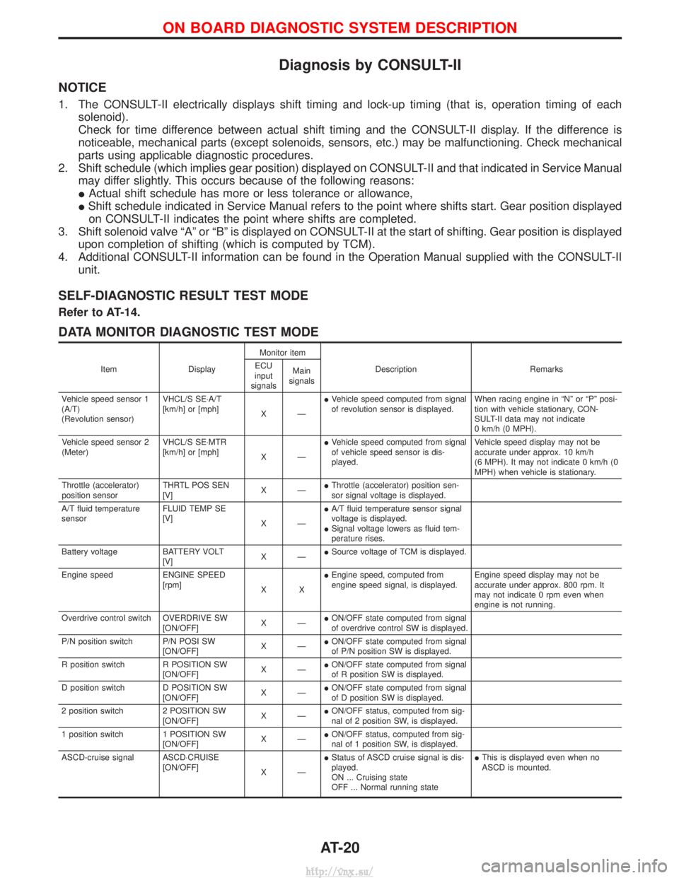
Diagnosis by CONSULT-II
NOTICE
1. The CONSULT-II electrically displays shift timing and lock-up timing (that is, operation timing of eachsolenoid).
Check for time difference between actual shift timing and the CONSULT-II display. If the difference is
noticeable, mechanical parts (except solenoids, sensors, etc.) may be malfunctioning. Check mechanical
parts using applicable diagnostic procedures.
2. Shift schedule (which implies gear position) displayed on CONSULT-II and that indicated in Service Manual may differ slightly. This occurs because of the following reasons:
IActual shift schedule has more or less tolerance or allowance,
I Shift schedule indicated in Service Manual refers to the point where shifts start. Gear position displayed
on CONSULT-II indicates the point where shifts are completed.
3. Shift solenoid valve ªAº or ªBº is displayed on CONSULT-II at the start of shifting. Gear position is displayed upon completion of shifting (which is computed by TCM).
4. Additional CONSULT-II information can be found in the Operation Manual supplied with the CONSULT-II unit.
SELF-DIAGNOSTIC RESULT TEST MODE
Refer to AT-14.
DATA MONITOR DIAGNOSTIC TEST MODE
Item DisplayMonitor item
Description Remarks
ECU
input
signals Main
signals
Vehicle speed sensor 1
(A/T)
(Revolution sensor) VHCL/S SE×A/T
[km/h] or [mph]
XÐI
Vehicle speed computed from signal
of revolution sensor is displayed. When racing engine in ªNº or ªPº posi-
tion with vehicle stationary, CON-
SULT-II data may not indicate
0 km/h (0 MPH).
Vehicle speed sensor 2
(Meter) VHCL/S SE×MTR
[km/h] or [mph]
XÐI
Vehicle speed computed from signal
of vehicle speed sensor is dis-
played. Vehicle speed display may not be
accurate under approx. 10 km/h
(6 MPH). It may not indicate 0 km/h (0
MPH) when vehicle is stationary.
Throttle (accelerator)
position sensor THRTL POS SEN
[V]
XÐI
Throttle (accelerator) position sen-
sor signal voltage is displayed.
A/T fluid temperature
sensor FLUID TEMP SE
[V]
XÐI
A/T fluid temperature sensor signal
voltage is displayed.
I Signal voltage lowers as fluid tem-
perature rises.
Battery voltage BATTERY VOLT [V]XÐI
Source voltage of TCM is displayed.
Engine speed ENGINE SPEED [rpm]XXI
Engine speed, computed from
engine speed signal, is displayed. Engine speed display may not be
accurate under approx. 800 rpm. It
may not indicate 0 rpm even when
engine is not running.
Overdrive control switch OVERDRIVE SW [ON/OFF]XÐI
ON/OFF state computed from signal
of overdrive control SW is displayed.
P/N position switch P/N POSI SW [ON/OFF]XÐI
ON/OFF state computed from signal
of P/N position SW is displayed.
R position switch R POSITION SW [ON/OFF]XÐI
ON/OFF state computed from signal
of R position SW is displayed.
D position switch D POSITION SW [ON/OFF]XÐI
ON/OFF state computed from signal
of D position SW is displayed.
2 position switch 2 POSITION SW [ON/OFF]XÐI
ON/OFF status, computed from sig-
nal of 2 position SW, is displayed.
1 position switch 1 POSITION SW [ON/OFF]XÐI
ON/OFF status, computed from sig-
nal of 1 position SW, is displayed.
ASCD-cruise signal ASCD×CRUISE [ON/OFF]XÐI
Status of ASCD cruise signal is dis-
played.
ON ... Cruising state
OFF ... Normal running state I
This is displayed even when no
ASCD is mounted.
ON BOARD DIAGNOSTIC SYSTEM DESCRIPTION
AT-20
http://vnx.su/
Page 837 of 1833
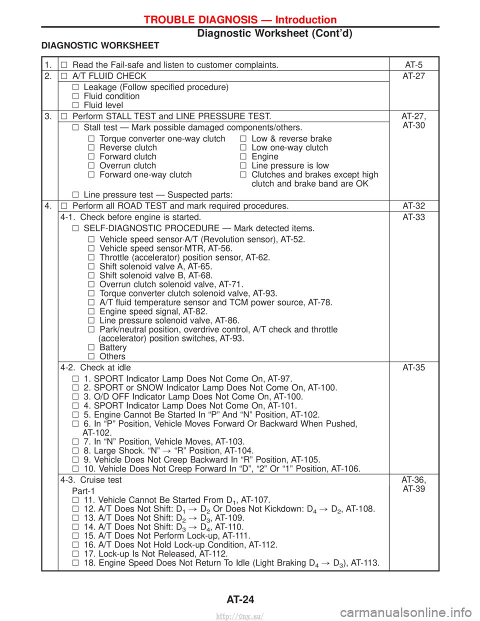
DIAGNOSTIC WORKSHEET
1.lRead the Fail-safe and listen to customer complaints. AT-5
2. lA/T FLUID CHECK AT-27
l Leakage (Follow specified procedure)
l Fluid condition
l Fluid level
3. lPerform STALL TEST and LINE PRESSURE TEST. AT-27,
AT-30
l Stall test Ð Mark possible damaged components/others.
l Torque converter one-way clutch
l Reverse clutch
l Forward clutch
l Overrun clutch
l Forward one-way clutch l
Low & reverse brake
l Low one-way clutch
l Engine
l Line pressure is low
l Clutches and brakes except high
clutch and brake band are OK
l Line pressure test Ð Suspected parts:
4. lPerform all ROAD TEST and mark required procedures. AT-32
4-1. Check before engine is started. AT-33 l SELF-DIAGNOSTIC PROCEDURE Ð Mark detected items.
l Vehicle speed sensor×A/T (Revolution sensor), AT-52.
l Vehicle speed sensor×MTR, AT-56.
l Throttle (accelerator) position sensor, AT-62.
l Shift solenoid valve A, AT-65.
l Shift solenoid valve B, AT-68.
l Overrun clutch solenoid valve, AT-71.
l Torque converter clutch solenoid valve, AT-93.
l A/T fluid temperature sensor and TCM power source, AT-78.
l Engine speed signal, AT-82.
l Line pressure solenoid valve, AT-86.
l Park/neutral position, overdrive control, A/T check and throttle
(accelerator) position switches, AT-93.
l Battery
l Others
4-2. Check at idle AT-35 l 1. SPORT Indicator Lamp Does Not Come On, AT-97.
l 2. SPORT or SNOW Indicator Lamp Does Not Come On, AT-100.
l 3. O/D OFF Indicator Lamp Does Not Come On, AT-100.
l 4. SPORT Indicator Lamp Does Not Come On, AT-101.
l 5. Engine Cannot Be Started In ªPº And ªNº Position, AT-102.
l 6. In ªPº Position, Vehicle Moves Forward Or Backward When Pushed,
AT-102.
l 7. In ªNº Position, Vehicle Moves, AT-103.
l 8. Large Shock. ªNº ,ªRº Position, AT-104.
l 9. Vehicle Does Not Creep Backward In ªRº Position, AT-105.
l 10. Vehicle Does Not Creep Forward In ªDº, ª2º Or ª1º Position, AT-106.
4-3. Cruise test AT-36,
AT-39
Part-1
l 11. Vehicle Cannot Be Started From D
1, AT-107.
l 12. A/T Does Not Shift: D
1,D2Or Does Not Kickdown: D4,D2, AT-108.
l 13. A/T Does Not Shift: D
2,D3, AT-109.
l 14. A/T Does Not Shift: D
3,D4, AT-110.
l 15. A/T Does Not Perform Lock-up, AT-111.
l 16. A/T Does Not Hold Lock-up Condition, AT-112.
l 17. Lock-up Is Not Released, AT-112.
l 18. Engine Speed Does Not Return To Idle (Light Braking D
4,D3), AT-113.
TROUBLE DIAGNOSIS Ð Introduction
Diagnostic Worksheet (Cont'd)
AT-24
http://vnx.su/
Page 840 of 1833

A/T Fluid Check
FLUID LEAKAGE CHECK
1. Clean area suspected of leaking. Ð for example, mating sur-face of converter housing and transmission case.
2. Start engine, apply foot brake, place selector lever in ªDº posi- tion and wait a few minutes.
3. Stop engine.
4. Check for fresh leakage.
FLUID CONDITION CHECK
Fluid color Suspected cause
Dark or black with burned odor Wear of frictional material
Milky pink Water contamination Ð Road water enter-
ing through filler tube or breather
Varnished fluid, light to dark
brown and tacky Oxidation Ð Over or under filling, Ð Over-
heating
FLUID LEVEL CHECK
Refer to MA section (ªChecking A/T Fluidº, ªCHASSIS AND BODY
MAINTENANCEº).
Stall Test
STALL TEST PROCEDURE
1. Check A/T and engine fluid levels. If necessary, add.
2. Drive vehicle for approx. 10 minutes or until engine oil and ATF
reach operating temperature.ATF operating temperature: 50 - 80ÉC (122 - 176ÉF)
3. Set parking brake and block wheels.
4. Install a tachometer where it can be seen by driver during test.
I It is good practice to put a mark on point of specified
engine rpm on indicator.
5. Start engine, apply foot brake, and place selector lever in ªDº position.
6. Accelerate to wide open throttle gradually while applying foot brake.
7. Quickly note the engine stall revolution and immediately release throttle.
I During test, never hold throttle wide open for more than 5
seconds.
Stall revolution: 2,450 - 2,700 rpm
SAT801A
SAT638A
SAT647B
SAT513G
SAT514G
TROUBLE DIAGNOSIS Ð Basic Inspection
AT-27
http://vnx.su/
Page 853 of 1833
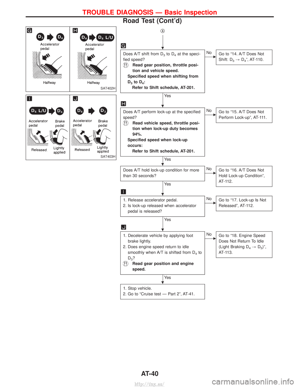
qA
Does A/T shift from D3to D4at the speci-
fied speed?
Read gear position, throttle posi-
tion and vehicle speed.
Specified speed when shifting from
D
3to D4:
Refer to Shift schedule, AT-201.
Ye s
ENo Go to ª14. A/T Does Not
Shift: D
3,D4º, AT-110.
Does A/T perform lock-up at the specified
speed?
Read vehicle speed, throttle posi-
tion when lock-up duty becomes
94%.
Specified speed when lock-up
occurs: Refer to Shift schedule, AT-201.
Ye s
ENo Go to ª15. A/T Does Not
Perform Lock-upº, AT-111.
Does A/T hold lock-up condition for more
than 30 seconds?
Ye s
ENoGo to ª16. A/T Does Not
Hold Lock-up Conditionº,
AT-112.
1. Release accelerator pedal.
2. Is lock-up released when accelerator pedal is released?
Ye s
ENo Go to ª17. Lock-up Is Not
Releasedº, AT-112.
1. Decelerate vehicle by applying foot
brake lightly.
2. Does engine speed return to idle smoothly when A/T is shifted from D
4to
D
3?
Read gear position and engine
speed.
Ye s
ENo Go to ª18. Engine Speed
Does Not Return To Idle
(Light Braking D
4,D3)º,
AT-113.
1. Stop vehicle.
2. Go to ªCruise test Ð Part 2º, AT-41.
SAT402H
SAT403H
H
H
H
H
H
H
TROUBLE DIAGNOSIS Ð Basic Inspection
Road Test (Cont'd)
AT-40
http://vnx.su/