Page 1185 of 1833
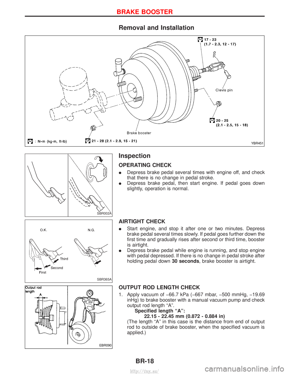
Removal and Installation
Inspection
OPERATING CHECK
IDepress brake pedal several times with engine off, and check
that there is no change in pedal stroke.
I Depress brake pedal, then start engine. If pedal goes down
slightly, operation is normal.
AIRTIGHT CHECK
IStart engine, and stop it after one or two minutes. Depress
brake pedal several times slowly. If pedal goes further down the
first time and gradually rises after second or third time, booster
is airtight.
I Depress brake pedal while engine is running, and stop engine
with pedal depressed. If there is no change in pedal stroke after
holding pedal down 30 seconds, brake booster is airtight.
OUTPUT ROD LENGTH CHECK
1. Apply vacuum of þ66.7 kPa (þ667 mbar, þ500 mmHg, þ19.69
inHg) to brake booster with a manual vacuum pump and check
output rod length ªAº.Specified length ªAº: 22.15 - 22.45 mm (0.872 - 0.884 in)
(The length ªAº in this case is the distance from end of output
rod to outside of brake booster, when the specified vacuum is
applied.)
YBR451
SBR002A
SBR365A
EBR090
BRAKE BOOSTER
BR-18
http://vnx.su/
Page 1186 of 1833
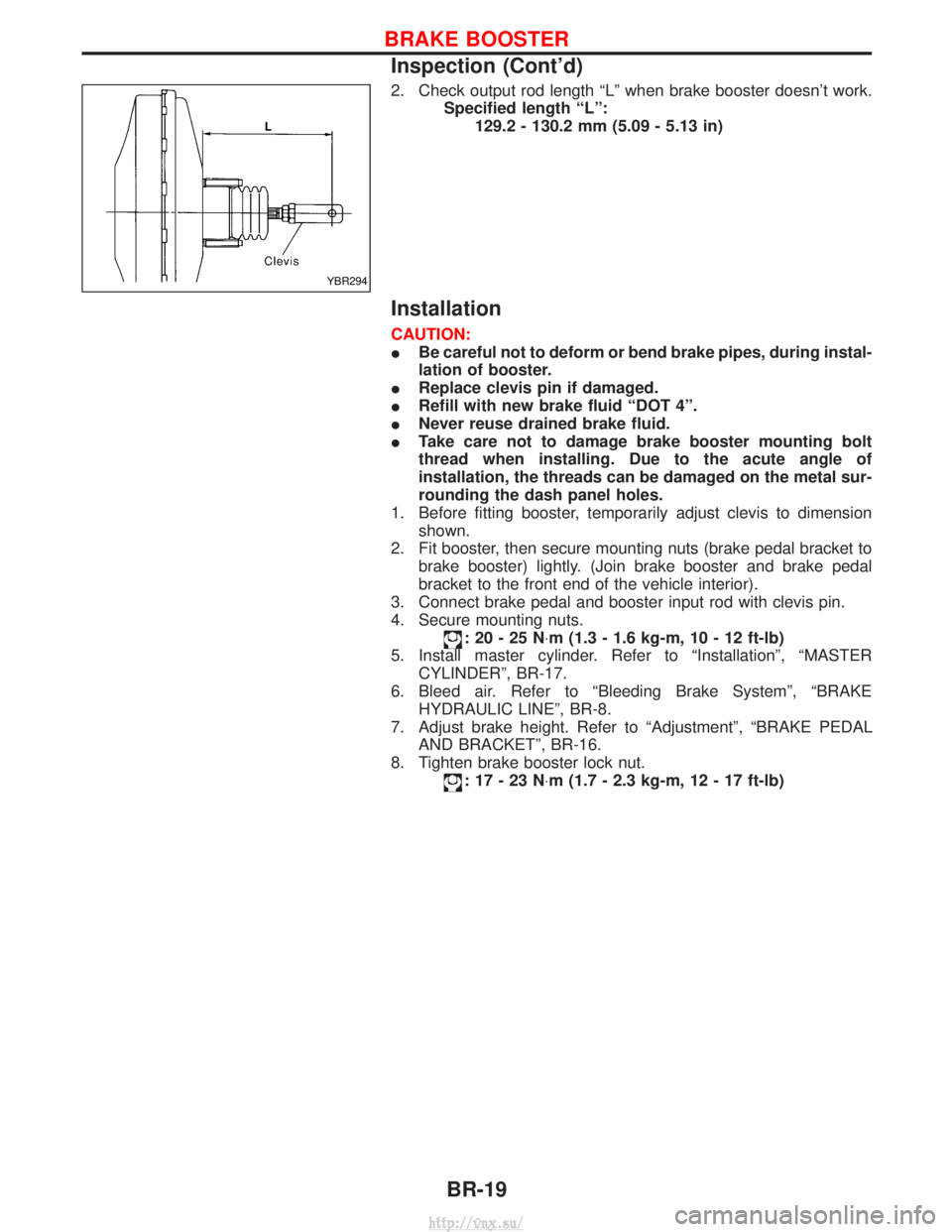
2. Check output rod length ªLº when brake booster doesn't work.Specified length ªLº:129.2 - 130.2 mm (5.09 - 5.13 in)
Installation
CAUTION:
IBe careful not to deform or bend brake pipes, during instal-
lation of booster.
I Replace clevis pin if damaged.
I Refill with new brake fluid ªDOT 4º.
I Never reuse drained brake fluid.
I Take care not to damage brake booster mounting bolt
thread when installing. Due to the acute angle of
installation, the threads can be damaged on the metal sur-
rounding the dash panel holes.
1. Before fitting booster, temporarily adjust clevis to dimension shown.
2. Fit booster, then secure mounting nuts (brake pedal bracket to brake booster) lightly. (Join brake booster and brake pedal
bracket to the front end of the vehicle interior).
3. Connect brake pedal and booster input rod with clevis pin.
4. Secure mounting nuts.
:20-25N ×m (1.3 - 1.6 kg-m, 10 - 12 ft-lb)
5. Install master cylinder. Refer to ªInstallationº, ªMASTER CYLINDERº, BR-17.
6. Bleed air. Refer to ªBleeding Brake Systemº, ªBRAKE HYDRAULIC LINEº, BR-8.
7. Adjust brake height. Refer to ªAdjustmentº, ªBRAKE PEDAL AND BRACKETº, BR-16.
8. Tighten brake booster lock nut.
:17-23N ×m (1.7 - 2.3 kg-m, 12 - 17 ft-lb)
YBR294
BRAKE BOOSTER
Inspection (Cont'd)
BR-19
http://vnx.su/
Page 1192 of 1833
ICheck inner wall of vacuum pump housing for wear. If
necessary, replace.
I Check rotor shaft for wear. If necessary, replace.
I Check valve locations and copper washers for bends or defor-
mation. If necessary, replace.
I Check that valve operates smoothly when slightly pushed.
Replace if necessary.
I Check for air leakage with 98 to 490 kPa (1.0 to 4.9 bar, 1 to
5 kg/cm
2, 14 to 71 psi) of air pressure.
Replace if necessary.
NBR134
SBR194
SBR195
VACUUM PUMP (TD27Ti engine model)
Inspection (Cont'd)
BR-25
http://vnx.su/
Page 1196 of 1833
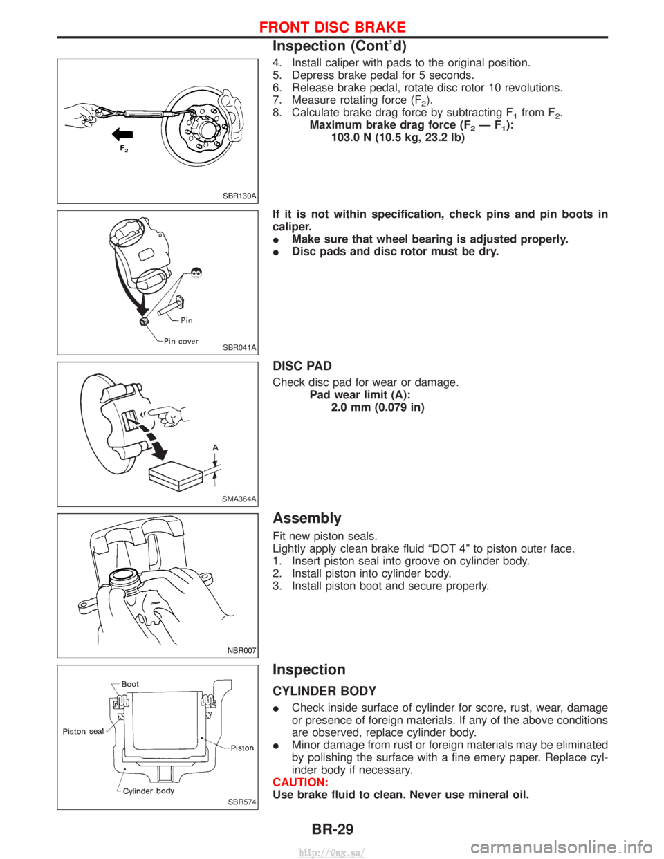
4. Install caliper with pads to the original position.
5. Depress brake pedal for 5 seconds.
6. Release brake pedal, rotate disc rotor 10 revolutions.
7. Measure rotating force (F
2).
8. Calculate brake drag force by subtracting F
1from F2.
Maximum brake drag force (F
2ÐF1):
103.0 N (10.5 kg, 23.2 lb)
If it is not within specification, check pins and pin boots in
caliper.
I Make sure that wheel bearing is adjusted properly.
I Disc pads and disc rotor must be dry.
DISC PAD
Check disc pad for wear or damage.
Pad wear limit (A):2.0 mm (0.079 in)
Assembly
Fit new piston seals.
Lightly apply clean brake fluid ªDOT 4º to piston outer face.
1. Insert piston seal into groove on cylinder body.
2. Install piston into cylinder body.
3. Install piston boot and secure properly.
Inspection
CYLINDER BODY
ICheck inside surface of cylinder for score, rust, wear, damage
or presence of foreign materials. If any of the above conditions
are observed, replace cylinder body.
I Minor damage from rust or foreign materials may be eliminated
by polishing the surface with a fine emery paper. Replace cyl-
inder body if necessary.
CAUTION:
Use brake fluid to clean. Never use mineral oil.
SBR130A
SBR041A
SMA364A
NBR007
SBR574
FRONT DISC BRAKE
Inspection (Cont'd)
BR-29
http://vnx.su/
Page 1205 of 1833
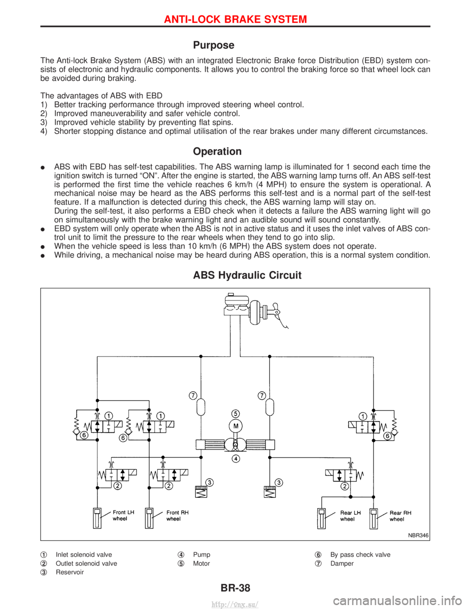
Purpose
The Anti-lock Brake System (ABS) with an integrated Electronic Brake force Distribution (EBD) system con-
sists of electronic and hydraulic components. It allows you to control the braking force so that wheel lock can
be avoided during braking.
The advantages of ABS with EBD
1) Better tracking performance through improved steering wheel control.
2) Improved maneuverability and safer vehicle control.
3) Improved vehicle stability by preventing flat spins.
4) Shorter stopping distance and optimal utilisation of the rear brakes under many different circumstances.
Operation
IABS with EBD has self-test capabilities. The ABS warning lamp is illuminated for 1 second each time the
ignition switch is turned ªONº. After the engine is started, the ABS warning lamp turns off. An ABS self-test
is performed the first time the vehicle reaches 6 km/h (4 MPH) to ensure the system is operational. A
mechanical noise may be heard as the ABS performs this self-test and is a normal part of the self-test
feature. If a malfunction is detected during this check, the ABS warning lamp will stay on.
During the self-test, it also performs a EBD check when it detects a failure the ABS warning light will go
on simultaneously with the brake warning light and an audible sound will sound constantly.
I EBD system will only operate when the ABS is not in active status and it uses the inlet valves of ABS con-
trol unit to limit the pressure to the rear wheels when they tend to go into slip.
I When the vehicle speed is less than 10 km/h (6 MPH) the ABS system does not operate.
I While driving, a mechanical noise may be heard during ABS operation, this is a normal system condition.
ABS Hydraulic Circuit
q1Inlet solenoid valve
q
2Outlet solenoid valve
q
3Reservoir q
4Pump
q
5Motor q
6By pass check valve
q
7Damper
NBR346
ANTI-LOCK BRAKE SYSTEM
BR-38
http://vnx.su/
Page 1206 of 1833
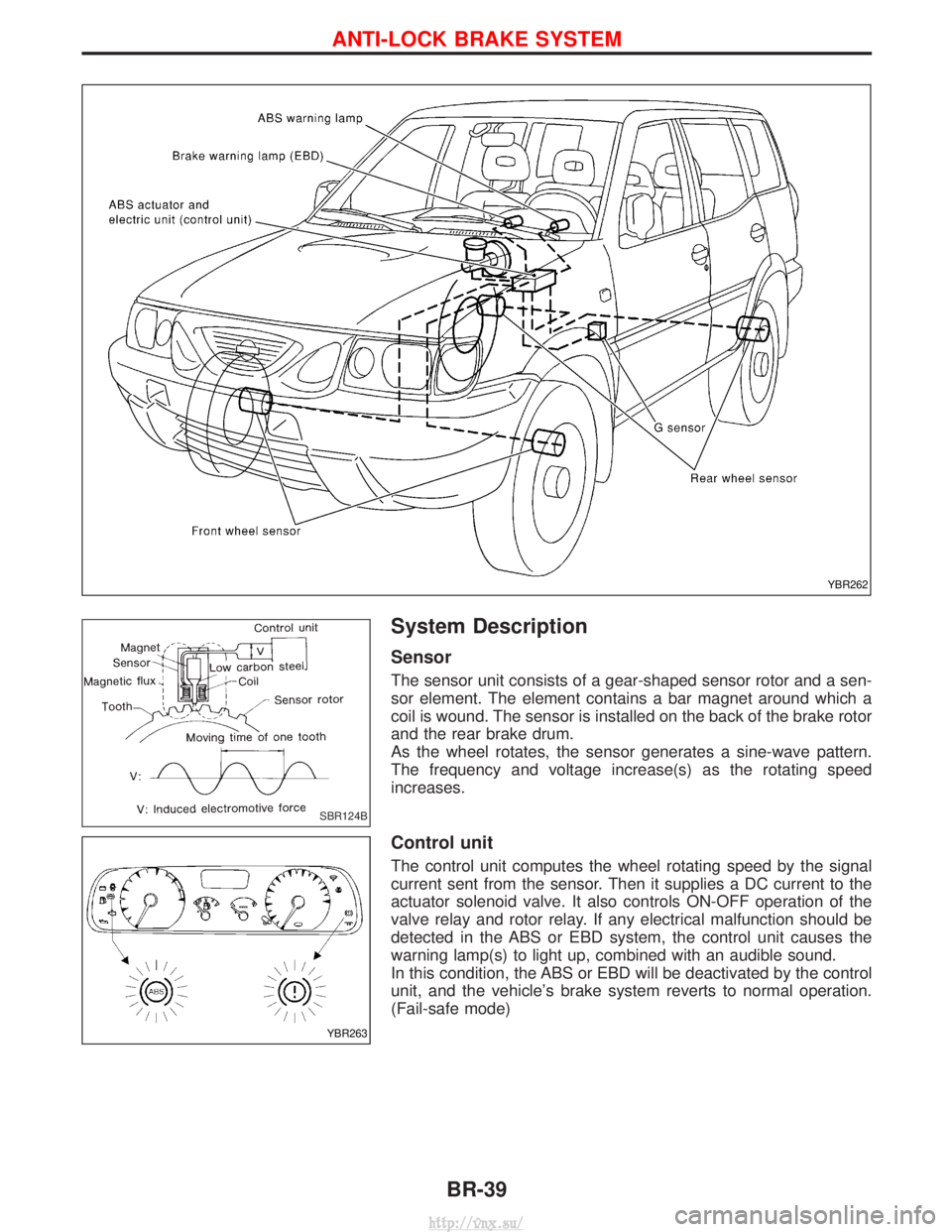
System Description
Sensor
The sensor unit consists of a gear-shaped sensor rotor and a sen-
sor element. The element contains a bar magnet around which a
coil is wound. The sensor is installed on the back of the brake rotor
and the rear brake drum.
As the wheel rotates, the sensor generates a sine-wave pattern.
The frequency and voltage increase(s) as the rotating speed
increases.
Control unit
The control unit computes the wheel rotating speed by the signal
current sent from the sensor. Then it supplies a DC current to the
actuator solenoid valve. It also controls ON-OFF operation of the
valve relay and rotor relay. If any electrical malfunction should be
detected in the ABS or EBD system, the control unit causes the
warning lamp(s) to light up, combined with an audible sound.
In this condition, the ABS or EBD will be deactivated by the control
unit, and the vehicle's brake system reverts to normal operation.
(Fail-safe mode)
YBR262
SBR124B
YBR263
ANTI-LOCK BRAKE SYSTEM
BR-39
http://vnx.su/
Page 1258 of 1833
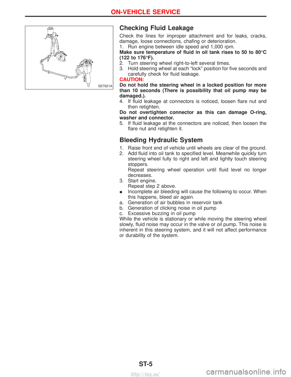
Checking Fluid Leakage
Check the lines for improper attachment and for leaks, cracks,
damage, loose connections, chafing or deterioration.
1. Run engine between idle speed and 1,000 rpm.
Make sure temperature of fluid in oil tank rises to 50 to 80ÉC
(122 to 176ÉF).
2. Turn steering wheel right-to-left several times.
3. Hold steering wheel at each ªlockº position for five seconds andcarefully check for fluid leakage.
CAUTION:
Do not hold the steering wheel in a locked position for more
than 10 seconds (There is possibility that oil pump may be
damaged.).
4. If fluid leakage at connectors is noticed, loosen flare nut and then retighten.
Do not overtighten connector as this can damage O-ring,
washer and connector.
5. If fluid leakage at the connectors are noticed, then loosen the flare nut and retighten it.
Bleeding Hydraulic System
1. Raise front end of vehicle until wheels are clear of the ground.
2. Add fluid into oil tank to specified level. Meanwhile quickly turnsteering wheel fully to right and left and lightly touch steering
stoppers.
Repeat steering wheel operation until fluid level no longer
decreases.
3. Start engine. Repeat step 2 above.
I Incomplete air bleeding will cause the following to occur. When
this happens, bleed air again.
a. Generation of air bubbles in reservoir tank
b. Generation of clicking noise in oil pump
c. Excessive buzzing in oil pump
While the vehicle is stationary or while moving the steering wheel
slowly, fluid noise may occur in the valve or oil pump. This noise is
inherent in this steering system, and it will not affect performance
or durability of the system.
SST621A
ON-VEHICLE SERVICE
ST-5
http://vnx.su/
Page 1264 of 1833
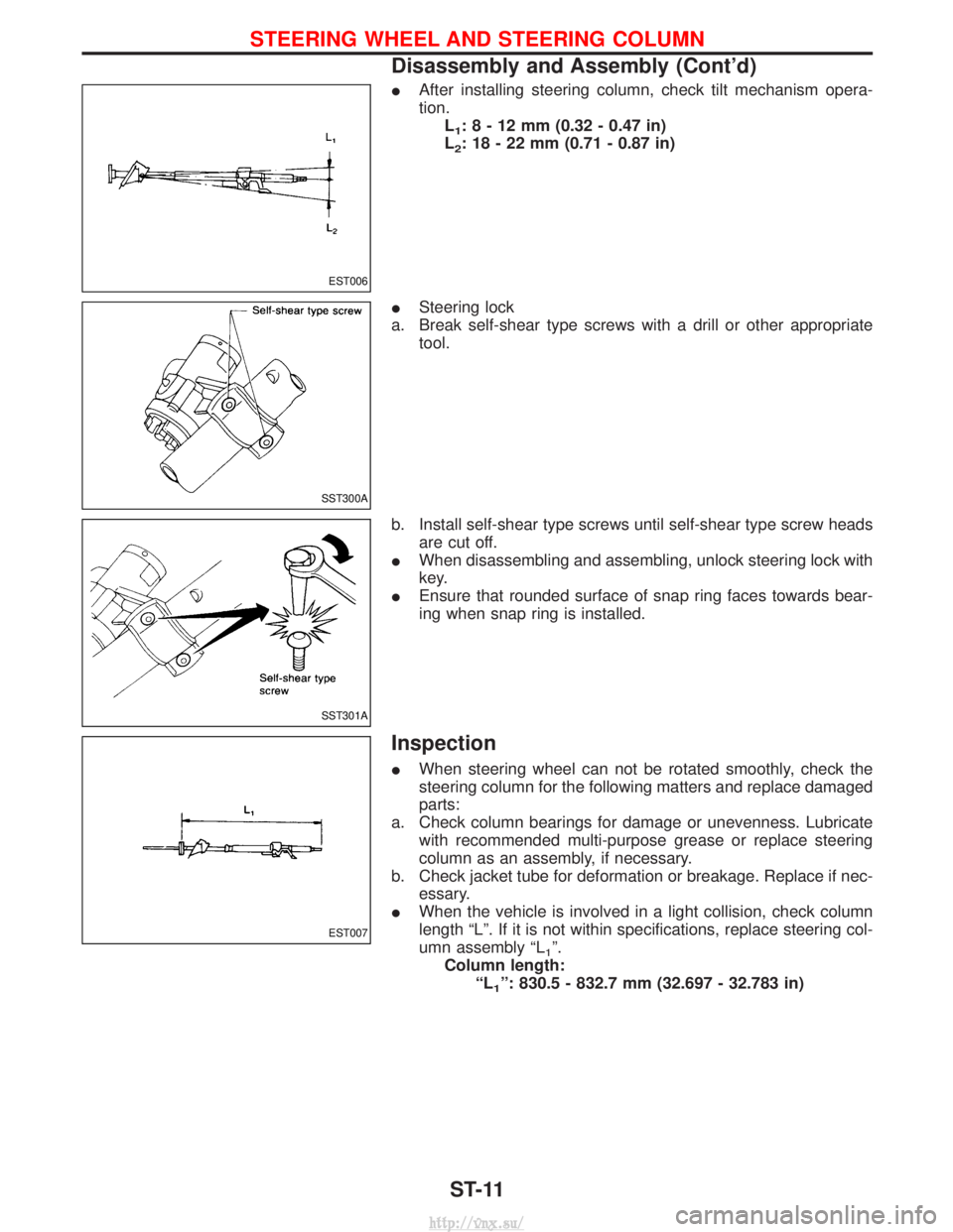
IAfter installing steering column, check tilt mechanism opera-
tion.
L
1:8-12mm (0.32 - 0.47 in)
L
2: 18 - 22 mm (0.71 - 0.87 in)
I Steering lock
a. Break self-shear type screws with a drill or other appropriate tool.
b. Install self-shear type screws until self-shear type screw heads are cut off.
I When disassembling and assembling, unlock steering lock with
key.
I Ensure that rounded surface of snap ring faces towards bear-
ing when snap ring is installed.
Inspection
IWhen steering wheel can not be rotated smoothly, check the
steering column for the following matters and replace damaged
parts:
a. Check column bearings for damage or unevenness. Lubricate with recommended multi-purpose grease or replace steering
column as an assembly, if necessary.
b. Check jacket tube for deformation or breakage. Replace if nec- essary.
I When the vehicle is involved in a light collision, check column
length ªLº. If it is not within specifications, replace steering col-
umn assembly ªL
1º.
Column length: ªL
1º: 830.5 - 832.7 mm (32.697 - 32.783 in)
EST006
SST300A
SST301A
EST007
STEERING WHEEL AND STEERING COLUMN
Disassembly and Assembly (Cont'd)
ST-11
http://vnx.su/